EP0087663B1 - Dispositif pour produire un champ électrique - Google Patents
Dispositif pour produire un champ électrique Download PDFInfo
- Publication number
- EP0087663B1 EP0087663B1 EP83101376A EP83101376A EP0087663B1 EP 0087663 B1 EP0087663 B1 EP 0087663B1 EP 83101376 A EP83101376 A EP 83101376A EP 83101376 A EP83101376 A EP 83101376A EP 0087663 B1 EP0087663 B1 EP 0087663B1
- Authority
- EP
- European Patent Office
- Prior art keywords
- soil
- situated
- electrode
- installation according
- cathode
- Prior art date
- Legal status (The legal status is an assumption and is not a legal conclusion. Google has not performed a legal analysis and makes no representation as to the accuracy of the status listed.)
- Expired
Links
- 230000005684 electric field Effects 0.000 title claims description 18
- 239000002689 soil Substances 0.000 claims description 42
- XLYOFNOQVPJJNP-UHFFFAOYSA-N water Substances O XLYOFNOQVPJJNP-UHFFFAOYSA-N 0.000 claims description 31
- 239000004033 plastic Substances 0.000 claims description 30
- 229920003023 plastic Polymers 0.000 claims description 30
- 229910052751 metal Inorganic materials 0.000 claims description 16
- 239000002184 metal Substances 0.000 claims description 16
- 238000009434 installation Methods 0.000 claims description 13
- OKTJSMMVPCPJKN-UHFFFAOYSA-N Carbon Chemical compound [C] OKTJSMMVPCPJKN-UHFFFAOYSA-N 0.000 claims description 12
- 239000004020 conductor Substances 0.000 claims description 12
- 239000000463 material Substances 0.000 claims description 10
- 229920003002 synthetic resin Polymers 0.000 claims description 8
- 239000000057 synthetic resin Substances 0.000 claims description 8
- 229910052799 carbon Inorganic materials 0.000 claims description 7
- 150000002500 ions Chemical class 0.000 claims description 6
- 235000013311 vegetables Nutrition 0.000 claims description 6
- 239000006185 dispersion Substances 0.000 claims description 4
- 229910021645 metal ion Inorganic materials 0.000 claims description 4
- NIXOWILDQLNWCW-UHFFFAOYSA-M Acrylate Chemical compound [O-]C(=O)C=C NIXOWILDQLNWCW-UHFFFAOYSA-M 0.000 claims description 3
- 229910002804 graphite Inorganic materials 0.000 claims description 3
- 239000010439 graphite Substances 0.000 claims description 3
- 239000006229 carbon black Substances 0.000 claims description 2
- 239000012876 carrier material Substances 0.000 claims description 2
- 239000003638 chemical reducing agent Substances 0.000 claims description 2
- 239000008187 granular material Substances 0.000 claims description 2
- 238000002156 mixing Methods 0.000 claims description 2
- 239000000243 solution Substances 0.000 claims description 2
- 230000003746 surface roughness Effects 0.000 claims description 2
- 238000005979 thermal decomposition reaction Methods 0.000 claims description 2
- 150000002738 metalloids Chemical group 0.000 claims 2
- 229920000965 Duroplast Polymers 0.000 claims 1
- 239000004638 Duroplast Substances 0.000 claims 1
- 150000002736 metal compounds Chemical class 0.000 claims 1
- 150000002737 metalloid compounds Chemical class 0.000 claims 1
- 229920000642 polymer Polymers 0.000 claims 1
- 150000003839 salts Chemical class 0.000 description 13
- 230000000694 effects Effects 0.000 description 7
- 230000008901 benefit Effects 0.000 description 5
- 229910001385 heavy metal Inorganic materials 0.000 description 5
- 239000007788 liquid Substances 0.000 description 5
- 239000002245 particle Substances 0.000 description 5
- 239000011521 glass Substances 0.000 description 4
- 238000000034 method Methods 0.000 description 4
- -1 polytetrafluoroethylene Polymers 0.000 description 4
- 229910052709 silver Inorganic materials 0.000 description 4
- 239000004332 silver Substances 0.000 description 4
- 230000008020 evaporation Effects 0.000 description 3
- 238000001704 evaporation Methods 0.000 description 3
- 238000002474 experimental method Methods 0.000 description 3
- 235000015097 nutrients Nutrition 0.000 description 3
- 230000008569 process Effects 0.000 description 3
- 239000013535 sea water Substances 0.000 description 3
- 239000000126 substance Substances 0.000 description 3
- XEEYBQQBJWHFJM-UHFFFAOYSA-N Iron Chemical compound [Fe] XEEYBQQBJWHFJM-UHFFFAOYSA-N 0.000 description 2
- BQCADISMDOOEFD-UHFFFAOYSA-N Silver Chemical compound [Ag] BQCADISMDOOEFD-UHFFFAOYSA-N 0.000 description 2
- 150000001450 anions Chemical class 0.000 description 2
- 150000001768 cations Chemical class 0.000 description 2
- 239000011248 coating agent Substances 0.000 description 2
- 238000000576 coating method Methods 0.000 description 2
- 238000010276 construction Methods 0.000 description 2
- 239000010949 copper Substances 0.000 description 2
- 229920006037 cross link polymer Polymers 0.000 description 2
- 238000010612 desalination reaction Methods 0.000 description 2
- 230000035622 drinking Effects 0.000 description 2
- 238000001962 electrophoresis Methods 0.000 description 2
- 239000003337 fertilizer Substances 0.000 description 2
- 239000003673 groundwater Substances 0.000 description 2
- 238000010438 heat treatment Methods 0.000 description 2
- 239000003864 humus Substances 0.000 description 2
- 230000008635 plant growth Effects 0.000 description 2
- 229920001343 polytetrafluoroethylene Polymers 0.000 description 2
- 239000004810 polytetrafluoroethylene Substances 0.000 description 2
- 238000001556 precipitation Methods 0.000 description 2
- 238000012545 processing Methods 0.000 description 2
- 230000000630 rising effect Effects 0.000 description 2
- 239000002352 surface water Substances 0.000 description 2
- 229920001187 thermosetting polymer Polymers 0.000 description 2
- 238000003809 water extraction Methods 0.000 description 2
- 229920000049 Carbon (fiber) Polymers 0.000 description 1
- RYGMFSIKBFXOCR-UHFFFAOYSA-N Copper Chemical compound [Cu] RYGMFSIKBFXOCR-UHFFFAOYSA-N 0.000 description 1
- 241000237858 Gastropoda Species 0.000 description 1
- 206010061217 Infestation Diseases 0.000 description 1
- 208000012868 Overgrowth Diseases 0.000 description 1
- 239000004952 Polyamide Substances 0.000 description 1
- 238000009825 accumulation Methods 0.000 description 1
- NIXOWILDQLNWCW-UHFFFAOYSA-N acrylic acid group Chemical group C(C=C)(=O)O NIXOWILDQLNWCW-UHFFFAOYSA-N 0.000 description 1
- 230000009471 action Effects 0.000 description 1
- 230000004913 activation Effects 0.000 description 1
- 230000032683 aging Effects 0.000 description 1
- 230000004888 barrier function Effects 0.000 description 1
- 230000015572 biosynthetic process Effects 0.000 description 1
- 239000004917 carbon fiber Substances 0.000 description 1
- 230000008859 change Effects 0.000 description 1
- 239000003610 charcoal Substances 0.000 description 1
- 150000001875 compounds Chemical class 0.000 description 1
- 238000011109 contamination Methods 0.000 description 1
- 229910052802 copper Inorganic materials 0.000 description 1
- 238000005260 corrosion Methods 0.000 description 1
- 230000007797 corrosion Effects 0.000 description 1
- 230000007423 decrease Effects 0.000 description 1
- 238000000151 deposition Methods 0.000 description 1
- 230000008021 deposition Effects 0.000 description 1
- 238000013461 design Methods 0.000 description 1
- 235000013399 edible fruits Nutrition 0.000 description 1
- 238000004070 electrodeposition Methods 0.000 description 1
- 238000005868 electrolysis reaction Methods 0.000 description 1
- 238000005370 electroosmosis Methods 0.000 description 1
- 230000002349 favourable effect Effects 0.000 description 1
- 230000004720 fertilization Effects 0.000 description 1
- 230000005669 field effect Effects 0.000 description 1
- 239000012530 fluid Substances 0.000 description 1
- 230000002538 fungal effect Effects 0.000 description 1
- 239000007789 gas Substances 0.000 description 1
- 229910052742 iron Inorganic materials 0.000 description 1
- 230000002262 irrigation Effects 0.000 description 1
- 238000003973 irrigation Methods 0.000 description 1
- 244000005700 microbiome Species 0.000 description 1
- 230000003204 osmotic effect Effects 0.000 description 1
- 229920002647 polyamide Polymers 0.000 description 1
- 229920000728 polyester Polymers 0.000 description 1
- 230000002035 prolonged effect Effects 0.000 description 1
- 230000000246 remedial effect Effects 0.000 description 1
- 238000005067 remediation Methods 0.000 description 1
- 238000009418 renovation Methods 0.000 description 1
- 230000000717 retained effect Effects 0.000 description 1
- 238000010850 salt effect Methods 0.000 description 1
- 239000004065 semiconductor Substances 0.000 description 1
- 239000004071 soot Substances 0.000 description 1
- 125000006850 spacer group Chemical group 0.000 description 1
- 230000036561 sun exposure Effects 0.000 description 1
- 238000012360 testing method Methods 0.000 description 1
- 230000008646 thermal stress Effects 0.000 description 1
Images

Classifications
-
- A—HUMAN NECESSITIES
- A01—AGRICULTURE; FORESTRY; ANIMAL HUSBANDRY; HUNTING; TRAPPING; FISHING
- A01G—HORTICULTURE; CULTIVATION OF VEGETABLES, FLOWERS, RICE, FRUIT, VINES, HOPS OR SEAWEED; FORESTRY; WATERING
- A01G25/00—Watering gardens, fields, sports grounds or the like
-
- A—HUMAN NECESSITIES
- A01—AGRICULTURE; FORESTRY; ANIMAL HUSBANDRY; HUNTING; TRAPPING; FISHING
- A01G—HORTICULTURE; CULTIVATION OF VEGETABLES, FLOWERS, RICE, FRUIT, VINES, HOPS OR SEAWEED; FORESTRY; WATERING
- A01G7/00—Botany in general
- A01G7/04—Electric or magnetic or acoustic treatment of plants for promoting growth
Definitions
- the invention relates to a system for establishing an electric field in the ground according to the preamble of claim 1.
- Electrodes made of polytetrafluoroethylene (PTFE), which is filled with conductive, corrosion-resistant and electrolytically resistant materials. These materials can be replaced by carbon, e.g. Charcoal, graphite or soot can be filled.
- PTFE polytetrafluoroethylene
- a generic system is known from FR-A-24 02 424.
- the electrodes of this previously known system are formed by metal wires or by a network of metal wires and accordingly do not have sufficient mechanical and chemical resistance.
- the invention has for its object to provide a system for building an electrical field of the known type, with which the construction of a large-area homogeneous electrical field is possible, which can be used in both active and passive operation, and the electrodes a high have chemical and mechanical resilience.
- the material combinations provided thereafter ensure that the at least one electrode, preferably the cathode, which is laid flat, does not decompose due to electrochemical processes even during prolonged operation, and that this electrode is mechanical Loads such as z. B. occur when driving with tractors and other processing equipment, reliably withstands.
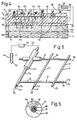
- FIG 1 is a section through different soil layers of a soil 1, z. B. a soil, shown.
- Humus 4 is provided in a vegetation area 2 below a surface 3. From this humus 4, trees 5, shrubs 6, flowers 7 and vegetables 8 obtain nutrients via the roots 9 to 12.
- Below this vegetation area 2 there is a floor area 13 made of sandy and highly water-permeable material, including a water-carrying floor area 14. The height of the water-bearing layers can be seen in a well 16 using a water level 15.
- a system 17 for establishing an electric field 18, of which electric field lines 19 are shown.
- This system 17 comprises a plurality of electrodes 21 used as cathodes 20, each of which is formed from a plurality of distribution lines 22 which are close to one another and run parallel to one another.
- the individual cathodes 20 are interconnected with a line system 23 which connects the cathodes 20 to an electrode 24 which is arranged under the water level 15 and is at the positive potential.
- the electrode 24 has a high conductance and a low contact resistance, this leads to good contacting of the amounts of liquid stored in the bottom region 14. As a result, the total amount of liquid with this soil layer is at the positive potential and forms the anode 25. If the anode 25 is connected to the cathodes 20 via the line system 23, the different pH in the vegetation area 2 or in the water-bearing soil area 14 builds up, a potential difference in the liquid due to the accumulation of salts. This potential difference leads to the formation of electrical fields 18, which are indicated schematically by field lines 13 between the individual cathodes 20 and the anode 25.
- the electrodes comprise a plurality of distribution lines 21 which are parallel to one another but close to one another creates broad, strong electric fields 18 with altogether low current strengths, so that damage occurs the root ends 28, the roots 9 to 12 and microorganisms in the vegetation area 2 can be avoided.
- this energy source consists of a solar energy cell 30 and an energy store, for. B. a battery 31, which may optionally be additionally provided for a buffer operation at night.
- the solar energy cell 30 is sufficient because the high fluid requirement for the trees 5, shrubs 6, flowers 7 and vegetables 8 in the flower beds 32 and in the vegetable beds 33 during the sun exposure.
- external energy is supplied to the electrodes 21, 24, namely the cathode 20 and anode 25, via the solar energy cell 30, so that there is increased water transport in the direction of the arrows 27, ie to the roots 9 to 12.
- the arrangement of the cathodes 20 ensures that the surface water cannot sink into the bottom region 13 so quickly after precipitation, since the cathodes 20 form a so-called horizontal barrier with the anode 25, which prevent water transport in the direction opposite to the arrows 27 .
- this also keeps the fertilizers introduced onto the soil surface 3 together with the moisture in the vegetation area 2, so that the roots 9 to 12 are supplied with sufficient nutrients. This results in faster plant growth and a higher yield and makes it possible to reduce irrigation from the soil surface.
- an arrangement of the electrodes 20 at a distance 34 of approximately 20 to 40 cm below the surface 3 allows the earth's crumb to be kept dry on the surface 3 and sufficient water transport in ensures the area of roots 11 and 12.
- a voltage of 6 volts is preferably emitted between the anode 25 and the cathodes 20 by the energy source 29 and a current of approximately 50 mA is fed in.
- the fields built up in this way are sufficient to effect sufficient electroosmotic water transport from the bottom area 14 into the vegetation area 2.
- a further advantage is achieved when the system according to FIG. 1 is used in glass houses that have been built with heat-insulating glass.
- the heat retained by the high insulating effect of the heat-insulating glass naturally causes a strong evaporation of the water supplied to the plants via the soil surface 3.
- This evaporation process of the water in turn generates cold, which requires an excessive amount of heating power.
- the bottom surface remains dry and the water evaporation is reduced. Due to the much lower humidity in the glass houses, less heating energy can be used and the fungal attack has been reduced.
- an electrode 35 can be placed around a trunk of the tree 5 for increased water transport in trees.
- This electrode 35 which is connected as a cathode 36, can be connected to the line system 23 via a line.
- the water transport is not only stimulated to the area of the roots 9, but also within the trunk and the yield, especially in fruit crops, can be increased.
- FIG. 2 shows an exemplary embodiment in which a cathode 38 forming an electrode 37 is formed by a network 39.
- This network 39 is arranged at a distance 40 below the floor surface 3.
- the net 39 is located in the region of roots 41 of a plant 42 and ensures that the nutrients or moisture is kept in the region of the roots 41 and the soil surface 3 is dry. Keeping the surface of the soil dry prevents harmful flora and fauna.
- the cathode 38 is interconnected via a line system 23 with an electrode 43, for example a plastic electrode filled with carbon.
- the cathode 38 or the anode 44 are connected via an energy source 29, which can be formed by a battery or another power generator. This results in an activation of the one that naturally results from the difference in pH between the water-carrying soil area 14 and the vegetation area 2 Potential difference. This potential difference is often given by the salts dissolved in the liquid in the bottom area 14 compared to the vegetation area 2. If, at the beginning of such an electroosmotic process, a strong electric field is built up by supplying external energy, the moisture 44 migrates through the bottom area 13 in the direction of the vegetation area 2 and thus the anode 44 also shifts towards, as indicated by dashed lines 3.
- the shorter distance between the anode 44 and the cathode 38 enables more intensive passive operation, since the potential differences between the water, which has a higher conductivity, and the vegetation area 2 an intensive field is built up in which there is a current flow which causes the osmotic water transport in the direction of the roots 41 of the plants 42.
- the cathode 38 designed as a net 35 has the advantage that the roots 41 of the plants 42 pass through the openings 46 of the net 39.
- the roots can therefore spread undisturbed and the heavy metal ions located in the ground are also separated on the large-area network 39.
- the fine roots 41 are therefore not damaged by the metal ions.
- the mesh size of the network 39 can be adjusted to a wide variety of applications.
- the surprising advantage of using a network as a cathode is, however, that a large-scale electrical field is built up in which the electrical conditions are approximately the same, so that a uniform water transport in the direction of the arrows 27 is achieved without the roots being destroyed by excessive currents becomes.
- the use of the system reduces the watering, both in terms of quantity and frequency, reduces fertilization, as the fertilizers are now no longer easily washed out of the vegetation area, and decreases the heavy metal concentration in the soil because of the electrochemical deposition of the corresponding ions on the installed negative electrode.
- a relatively coarse-mesh grid is advantageously installed, which allows the roots of the plantings to pass through.
- the position of the installed grid with respect to the floor surface is also of great influence. With a favorable installation depth, it can be achieved that the floor surface remains practically dry. This prevents overgrowth with unwanted flora, especially moss.
- the infestation of the ground surface with harmful fauna, such as snails, etc. is also reduced.
- the circuit connected by strands showed a voltage of 0.6 volts and a current of 3.2 mA.
- FIG. 3 in accordance with divisional application EP-A-02 00 936 (application number: 86 104 735.5), a system 47 for water extraction or for the simultaneous water supply of plants is shown.
- This system 47 comprises an electrode 49, formed in a deeper water-carrying floor area 14 by a carbon rod 48, with which the moisture in the floor area 14 is applied with a positive potential, so that this entire bottom area 14 acts as an anode 50.
- Electrodes 51, 52 are bonded underneath the bottom surface 3.
- the electrode 51 is formed by a network 53 - as will be described in more detail in FIG. 5 - or a conductive plastic 54. With the drainage pipes 55 coated. Drainage pipes 56 are also arranged below the network 53.
- a plastic drainage pipe with a diameter of 5 cm was then laid under part of the 3 m long strip.
- the horticultural business is located about 15 m above the coast, so it can be assumed that at least some of the water-bearing layers below the test area contain sea water. Sea water was now collected in the drain pipe, which was clear and left practically no salty impression when drinking.
- an installation 58 is shown as it is used for the desalination of soils 1, in particular in vegetation area 2.
- an electrode 61 formed by a network 60 is arranged in the vegetation area 2 between the root ends 59 and the soil surface 3.
- a further electrode 62, likewise formed by a network 60, is arranged below the root ends 59.
- heavy metals 63 and salts 64 are now present in the vegetation area. This is very common, particularly in the edge area or median strip area of heavily trafficked road through the salt scattering or median strip area of precipitation, the car exhaust gases.
- the electrode 62 is now connected to the positive and the electrode 61 to the negative potential of an energy source 23, for example a battery 65, electrophoresis or electrolysis occurs.
- the positive metal ions namely the cations 66, such as. B. K + , Cu 2 +. PB 2+ , Na + and Ca 2 + consequently migrate to the electrode 61 connected to a negative pontential and, as further indicated schematically, deposit on the network 60 on which this electrode 61 forms.
- the negatively charged salt residue namely the anions 67 and the hydroxide ions, such as. B. CI-, No 3- , P 04 3-, S 04 2-, Hco 3- , Coo-, Oh- and Ch3, on the other hand, migrate in the direction of the lower bottom region 13 to the electrode 62 connected to positive potential and are deposited there .
- an electrode 68 can be arranged in deeper water-bearing soil layers 14 for the remediation of the plants or for replanting and connected to positive potential, as indicated by dash-dotted lines.
- the two electrodes 61, 62 are then connected to negative potential and both serve as electrodes.
- the two grids 60 of the electrodes 61 and 62 are preferably connected to one another here by a connecting line 65, as is also indicated by dashed lines. so that they are at the same potential. This means that there can be no electrochemical contamination due to pH differences in the region of the two electrodes 61 and 62.
- the anions 67 originally deposited in the area of the electrode 62 namely the “salt residues”, move further in the direction of the lower-lying bottom layers 14 and are deposited in the area of this water-carrying bottom layer. This will completely remove them from the vegetation area.
- increased water transport occurs in the direction of the root ends 58, so that after the renovation of the vegetation area 2 accelerated plant growth occurs or new plantings can develop positively after a short time.
- FIG. 5 shows the network 39 which forms the cathode 38 and which is connected to a line system 22, for example with the interposition of an energy source 29 and an electrode 43.
- the electrode 43 can be formed by a metal rod 71 which is surrounded by an electrically conductive plastic 72.
- the network 39 consists of individual threads 73, 74, which also form the distribution lines 21.
- These threads 73, 74 can consist of a conductive plastic 75, which is formed in the manner of a thermoset with a macromolecular structure and z.
- B consists of an acrylate with at least partially cross-linked polymers.
- threads 76 made of carbon or threads 77 made of metal, which are preferably provided with a silver coating 78 can be embedded.
- these threads 76, 77 are at least embedded in a power supply line 79 which connects the network 39 to the line system 23.
- the carbon and metal threads 76, 77 can be made of any plastic, e.g. B. polyamide, acrylic, polyester or the like.
- the threads 73 or 74 of the network 39 can be embedded.
- the network is, as is indicated schematically on part of the network 39, embedded in a conductive plastic 75.
- FIG. 6 shows a distribution line 21 which comprises a conductor 80 composed of a plurality of individual strands made of metal 81 or carbon fibers.
- This conductor 80 is surrounded by a silver layer 82 and in a conductive plastic 83 in the manner of a thermoset with a macromolecular structure, for. B. embedded in an acrylate with at least partially crosslinked polymers.
- plastics 72, 75 and 83 used according to the invention contain synthetic resin dispersions, synthetic resin solutions or synthetic resins mixed with metal or semimetal compounds or their solutions in an amount, so that approximately one metal per synthetic resin molecule or semi-metal atom comes and which, after mixing and adding reducing agent in a slight excess or by known thermal decomposition, contains metal or semi-metal atoms and in the case of the ions formed or still present is washed out and the dispersions, solutions or granules are further processed with graphite or carbon black are.
- plastics are not only resistant to chemical and electrochemical influences, but also have a high resistance to aging, since they contain no ions and therefore hardly change when exposed to electrical currents.
- plastics described above can be used advantageously in conjunction with the various exemplary embodiments shown in FIGS. 1 to 4 and have proven extremely useful in the experiments described above. Another advantage of these plastics is that they have high surface adhesion and surface roughness
- the electrodes 21 formed by distribution lines 22 at a distance transversely to the longitudinal direction thereof by means of spacers, so that an approximately uniform distance between the distribution lines 22 can be maintained when introduced into the floor areas.
- This also results in a network or grid-shaped arrangement, but the difference is that the conductive connection is predominantly in the longitudinal direction of the individual distribution lines.
- it will also be necessary in this embodiment to establish cross-connections between the individual distribution lines 22 at certain larger intervals in order to be able to produce a bypass effect via another distribution line if one of these lines is interrupted.
- the distribution lines or the networks used are extremely flexible and free of tension so that a resilience does not build up when they are deformed.
Landscapes
- Life Sciences & Earth Sciences (AREA)
- Environmental Sciences (AREA)
- Engineering & Computer Science (AREA)
- Water Supply & Treatment (AREA)
- Biodiversity & Conservation Biology (AREA)
- Botany (AREA)
- Ecology (AREA)
- Forests & Forestry (AREA)
- Cultivation Of Plants (AREA)
- Investigation Of Foundation Soil And Reinforcement Of Foundation Soil By Compacting Or Drainage (AREA)
Claims (11)
Priority Applications (2)
| Application Number | Priority Date | Filing Date | Title |
|---|---|---|---|
| AT83101376T ATE32546T1 (de) | 1982-02-16 | 1983-02-12 | Anlage zum aufbau eines elektrischen feldes. |
| DE8383101376T DE3375709D1 (en) | 1982-02-16 | 1983-02-12 | Device for producing an electric field |
Applications Claiming Priority (2)
| Application Number | Priority Date | Filing Date | Title |
|---|---|---|---|
| CH961/82 | 1982-02-16 | ||
| CH96182 | 1982-02-16 |
Related Child Applications (2)
| Application Number | Title | Priority Date | Filing Date |
|---|---|---|---|
| EP86104734.8 Division-Into | 1986-04-07 | ||
| EP86104735.5 Division-Into | 1986-04-07 |
Publications (2)
| Publication Number | Publication Date |
|---|---|
| EP0087663A1 EP0087663A1 (fr) | 1983-09-07 |
| EP0087663B1 true EP0087663B1 (fr) | 1988-02-24 |
Family
ID=4199212
Family Applications (3)
| Application Number | Title | Priority Date | Filing Date |
|---|---|---|---|
| EP86104735A Ceased EP0200936A1 (fr) | 1982-02-16 | 1983-02-12 | Procédé pour augmenter l'humidité du sol par électro-osmose |
| EP86104734A Withdrawn EP0197537A1 (fr) | 1982-02-16 | 1983-02-12 | Procédé pour augmenter l'humidité des sols |
| EP83101376A Expired EP0087663B1 (fr) | 1982-02-16 | 1983-02-12 | Dispositif pour produire un champ électrique |
Family Applications Before (2)
| Application Number | Title | Priority Date | Filing Date |
|---|---|---|---|
| EP86104735A Ceased EP0200936A1 (fr) | 1982-02-16 | 1983-02-12 | Procédé pour augmenter l'humidité du sol par électro-osmose |
| EP86104734A Withdrawn EP0197537A1 (fr) | 1982-02-16 | 1983-02-12 | Procédé pour augmenter l'humidité des sols |
Country Status (5)
| Country | Link |
|---|---|
| EP (3) | EP0200936A1 (fr) |
| AR (1) | AR228823A1 (fr) |
| BR (1) | BR8300762A (fr) |
| ES (1) | ES519700A0 (fr) |
| IL (1) | IL67934A0 (fr) |
Cited By (1)
| Publication number | Priority date | Publication date | Assignee | Title |
|---|---|---|---|---|
| CN105205215A (zh) * | 2015-08-21 | 2015-12-30 | 吴龙华 | 一种计算不同状态挺水植被水流阻力的方法 |
Families Citing this family (12)
| Publication number | Priority date | Publication date | Assignee | Title |
|---|---|---|---|---|
| AT396319B (de) * | 1984-12-04 | 1993-08-25 | Nogler & Daum Eltac | Verfahren und vorrichtung zum aufbau eines elektrischen gleichfeldes in einer pflanze |
| AT396700B (de) * | 1986-05-07 | 1993-11-25 | Nogler & Daum Eltac | Anlage zum entfeuchten (austrocknen) von bauwerken unter verwendung von elektroden |
| FR2609860A1 (fr) * | 1987-01-27 | 1988-07-29 | Laurens Pierre | Procede d'activation de la vitalite, de la croissance et de l'immunisation des vegetaux |
| NL188415C (nl) * | 1987-08-27 | 1992-06-16 | Ir Frans Gustaaf Van Der Hoeve | Werkwijze voor het verwijderen van zware metalen uit daarmee verontreinigde grond of bodem. |
| NL8702437A (nl) * | 1987-10-13 | 1989-05-01 | Geo Kinetics B V I O | Werkwijze voor het conditioneren van grondmateriaal door elektrokinetische behandeling, elektrisch stroomsysteem voor toepassing van de werkwijze alsmede elektrode-behuizing voor toepassing in het elektrische stroomsysteem. |
| GB2210765B (en) * | 1987-12-11 | 1991-06-12 | Gerald Hugh Sidaway | Method of plant culture |
| US5405509A (en) * | 1989-05-08 | 1995-04-11 | Ionex | Remediation of a bulk source by electropotential ion transport using a host receptor matrix |
| EP0483286A4 (en) * | 1989-07-21 | 1992-07-01 | Ionex | Method of removing ions |
| GB9713235D0 (en) * | 1997-06-23 | 1997-08-27 | Netlon Ltd | Electrically-conducting element |
| WO2007127783A1 (fr) | 2006-04-26 | 2007-11-08 | Vectrix Corporation | Véhicule avec système d'inclinaison verrouillable |
| US10172298B1 (en) * | 2011-05-04 | 2019-01-08 | Thomas Russell Traficante | Garden planting guide/irrigation system |
| CN112570437A (zh) * | 2020-11-26 | 2021-03-30 | 北京建工环境修复股份有限公司 | 一种原位热传导耦合电渗井点降水修复有机污染场地的系统和方法 |
Family Cites Families (2)
| Publication number | Priority date | Publication date | Assignee | Title |
|---|---|---|---|---|
| FR693414A (fr) * | 1930-04-05 | 1930-11-20 | Procédé et dispositif d'irrigation électrique du sol | |
| FR2403424A1 (fr) * | 1977-09-19 | 1979-04-13 | Paysant Eugene | Humidification des sols arides |
-
1983
- 1983-02-10 AR AR292081A patent/AR228823A1/es active
- 1983-02-11 BR BR8300762A patent/BR8300762A/pt unknown
- 1983-02-11 ES ES519700A patent/ES519700A0/es active Granted
- 1983-02-12 EP EP86104735A patent/EP0200936A1/fr not_active Ceased
- 1983-02-12 EP EP86104734A patent/EP0197537A1/fr not_active Withdrawn
- 1983-02-12 EP EP83101376A patent/EP0087663B1/fr not_active Expired
- 1983-02-16 IL IL67934A patent/IL67934A0/xx unknown
Cited By (1)
| Publication number | Priority date | Publication date | Assignee | Title |
|---|---|---|---|---|
| CN105205215A (zh) * | 2015-08-21 | 2015-12-30 | 吴龙华 | 一种计算不同状态挺水植被水流阻力的方法 |
Also Published As
| Publication number | Publication date |
|---|---|
| AR228823A1 (es) | 1983-04-15 |
| EP0197537A1 (fr) | 1986-10-15 |
| EP0200936A1 (fr) | 1986-11-12 |
| ES8406610A1 (es) | 1984-08-01 |
| IL67934A0 (en) | 1983-06-15 |
| BR8300762A (pt) | 1983-11-16 |
| EP0087663A1 (fr) | 1983-09-07 |
| ES519700A0 (es) | 1984-08-01 |
Similar Documents
| Publication | Publication Date | Title |
|---|---|---|
| EP0087663B1 (fr) | Dispositif pour produire un champ électrique | |
| DE69514365T2 (de) | Kapillares bewässerungssystem für den wurzelbereich | |
| US4678554A (en) | Method and installation for generating an electrical field in the soil | |
| DE69931662T2 (de) | Elektrokinetische, geosynthetische struktur | |
| CH715708B1 (de) | Verfahren zur Verfüllung einer auf Biomassenzirkulation basierten Pflanzenkläranlage | |
| DE2946990A1 (de) | Bewaesserungs- und draenage-system | |
| DE60008033T2 (de) | Verfahren zur Flächebegrünung und Behälter mit Wasservorrat zur Verwendung in diesem Verfahren | |
| EP0238941A1 (fr) | Méthode et dispositif pour irriguer des sols | |
| CH624828A5 (fr) | ||
| EP0892764B1 (fr) | Transformation de boues de curage en humus | |
| WO1986003372A1 (fr) | Procede et dispositif pour etablir un champ electrique equipotentiel dans le sol | |
| DE60316928T2 (de) | Ausgerüstete pflanzungen zu behandlung von organischen abwässern durch biologische sanierung | |
| DE102013201957A1 (de) | Baumbewässerungssystem | |
| DE69921623T2 (de) | Verfahren zur Behandlung von Entwässerungsflüssigkeit | |
| DE3418493C2 (fr) | ||
| DE3329100A1 (de) | Verfahren zum schutz erdverlegter gegenstaende vor einer beschaedigung durch pflanzenwurzeln | |
| AT410158B (de) | Bodengemisch | |
| DE60315149T2 (de) | Struktur von konditionnertem partikelförmigen substrat und verfahren zum konditionnieren von partikelförmigem substrat | |
| EP0383109A1 (fr) | Utilisation de matériau d'écorce pour la réduction de la teneur en nitrate dans les eaux souterraines et dans l'eau potable ou dans l'eau de surface | |
| LU602656B1 (de) | Ein Verfahren zur Wasserspeicherung und Bodenerhaltung in Karstversteppungsgebieten auf der Grundlage der Regulierung von Bodenmikroorganismen | |
| DE3118109A1 (de) | Verfahren zur beeinflussung des wassertransports durch erdboden | |
| DE3806973A1 (de) | Pflanzenversorgungssystem | |
| DE3344945A1 (de) | Verfahren und vorrichtung zur erdlosen aufzucht und kultivierung von pflanzen auf schiefen ebenen, vorzugsweise im freien | |
| DE202024001564U1 (de) | Wasserleitvorrichtung | |
| DE102005029848A1 (de) | Verfahren zur Gewinnung von Biomasse, Plantage und Erntemaschine |
Legal Events
| Date | Code | Title | Description |
|---|---|---|---|
| PUAI | Public reference made under article 153(3) epc to a published international application that has entered the european phase |
Free format text: ORIGINAL CODE: 0009012 |
|
| AK | Designated contracting states |
Designated state(s): AT BE CH DE FR GB IT LI NL SE |
|
| 17P | Request for examination filed |
Effective date: 19831022 |
|
| GRAA | (expected) grant |
Free format text: ORIGINAL CODE: 0009210 |
|
| AK | Designated contracting states |
Kind code of ref document: B1 Designated state(s): AT BE CH DE FR GB IT LI NL SE |
|
| PG25 | Lapsed in a contracting state [announced via postgrant information from national office to epo] |
Ref country code: NL Effective date: 19880224 Ref country code: IT Free format text: LAPSE BECAUSE OF FAILURE TO SUBMIT A TRANSLATION OF THE DESCRIPTION OR TO PAY THE FEE WITHIN THE PRESCRIBED TIME-LIMIT;WARNING: LAPSES OF ITALIAN PATENTS WITH EFFECTIVE DATE BEFORE 2007 MAY HAVE OCCURRED AT ANY TIME BEFORE 2007. THE CORRECT EFFECTIVE DATE MAY BE DIFFERENT FROM THE ONE RECORDED. Effective date: 19880224 Ref country code: FR Free format text: THE PATENT HAS BEEN ANNULLED BY A DECISION OF A NATIONAL AUTHORITY Effective date: 19880224 Ref country code: BE Effective date: 19880224 |
|
| REF | Corresponds to: |
Ref document number: 32546 Country of ref document: AT Date of ref document: 19880315 Kind code of ref document: T |
|
| PG25 | Lapsed in a contracting state [announced via postgrant information from national office to epo] |
Ref country code: SE Effective date: 19880229 |
|
| REF | Corresponds to: |
Ref document number: 3375709 Country of ref document: DE Date of ref document: 19880331 |
|
| EN | Fr: translation not filed | ||
| NLV1 | Nl: lapsed or annulled due to failure to fulfill the requirements of art. 29p and 29m of the patents act | ||
| GBV | Gb: ep patent (uk) treated as always having been void in accordance with gb section 77(7)/1977 [no translation filed] | ||
| PG25 | Lapsed in a contracting state [announced via postgrant information from national office to epo] |
Ref country code: GB Free format text: LAPSE BECAUSE OF NON-PAYMENT OF DUE FEES Effective date: 19881122 |
|
| PLBE | No opposition filed within time limit |
Free format text: ORIGINAL CODE: 0009261 |
|
| STAA | Information on the status of an ep patent application or granted ep patent |
Free format text: STATUS: NO OPPOSITION FILED WITHIN TIME LIMIT |
|
| 26N | No opposition filed | ||
| PGFP | Annual fee paid to national office [announced via postgrant information from national office to epo] |
Ref country code: CH Payment date: 19910208 Year of fee payment: 9 |
|
| PGFP | Annual fee paid to national office [announced via postgrant information from national office to epo] |
Ref country code: DE Payment date: 19910425 Year of fee payment: 9 |
|
| PG25 | Lapsed in a contracting state [announced via postgrant information from national office to epo] |
Ref country code: LI Effective date: 19920229 Ref country code: CH Effective date: 19920229 |
|
| REG | Reference to a national code |
Ref country code: CH Ref legal event code: PL |
|
| PG25 | Lapsed in a contracting state [announced via postgrant information from national office to epo] |
Ref country code: DE Effective date: 19921103 |
|
| PGFP | Annual fee paid to national office [announced via postgrant information from national office to epo] |
Ref country code: AT Payment date: 19950216 Year of fee payment: 13 |
|
| PG25 | Lapsed in a contracting state [announced via postgrant information from national office to epo] |
Ref country code: AT Effective date: 19960212 |