EP0087774A1 - Dispositif pour tourner des pages - Google Patents
Dispositif pour tourner des pages Download PDFInfo
- Publication number
- EP0087774A1 EP0087774A1 EP83101847A EP83101847A EP0087774A1 EP 0087774 A1 EP0087774 A1 EP 0087774A1 EP 83101847 A EP83101847 A EP 83101847A EP 83101847 A EP83101847 A EP 83101847A EP 0087774 A1 EP0087774 A1 EP 0087774A1
- Authority
- EP
- European Patent Office
- Prior art keywords
- page
- turning
- book
- pages
- unit
- Prior art date
- Legal status (The legal status is an assumption and is not a legal conclusion. Google has not performed a legal analysis and makes no representation as to the accuracy of the status listed.)
- Ceased
Links
- 230000008878 coupling Effects 0.000 claims description 10
- 238000010168 coupling process Methods 0.000 claims description 10
- 238000005859 coupling reaction Methods 0.000 claims description 10
- 238000010276 construction Methods 0.000 claims description 4
- 230000000717 retained effect Effects 0.000 claims description 3
- 230000000694 effects Effects 0.000 description 7
- 230000007246 mechanism Effects 0.000 description 4
- 230000000994 depressogenic effect Effects 0.000 description 3
- 230000004048 modification Effects 0.000 description 3
- 238000012986 modification Methods 0.000 description 3
- 238000013459 approach Methods 0.000 description 2
- 238000010586 diagram Methods 0.000 description 2
- 230000009471 action Effects 0.000 description 1
- 229920003023 plastic Polymers 0.000 description 1
Images


Classifications
-
- B—PERFORMING OPERATIONS; TRANSPORTING
- B42—BOOKBINDING; ALBUMS; FILES; SPECIAL PRINTED MATTER
- B42D—BOOKS; BOOK COVERS; LOOSE LEAVES; PRINTED MATTER CHARACTERISED BY IDENTIFICATION OR SECURITY FEATURES; PRINTED MATTER OF SPECIAL FORMAT OR STYLE NOT OTHERWISE PROVIDED FOR; DEVICES FOR USE THEREWITH AND NOT OTHERWISE PROVIDED FOR; MOVABLE-STRIP WRITING OR READING APPARATUS
- B42D9/00—Bookmarkers; Spot indicators; Devices for holding books open; Leaf turners
- B42D9/04—Leaf turners
Definitions
- the present invention relates to page-turning devices, such as are used for turning the pages of bound music pads or other bound books.
- An object of the present invention is to provide a new page-turning device having a number of improvements, as will be described more particularly below.
- a page-turning device for turning the pages of a book bound along its center-line, comprising: a holder for the book; a rotatable page-turning unit supported on the holder along one horizontal edge at one side of the book center-line for individually turning the pages; and a drive for rotating the page-turning unit; characterized in that the drive is bi-directional for selectively driving the page-turning unit in either the forward direction or the reverse direction; and in that the page-turning unit includes an arm of crescent shape having an outer convex surface engageable with the underface of the uppermost page on one side of the book center-line for turning same when the page-turning unit is driven by the drive in the forward direction, the crescent-shape arm having an inner concave surface engageable with the underface of the uppermost page on the other side of the book center-line for turning same when the page-turning unit is driven by the drive in the reverse direction.
- the page-turning unit may include a helical recess terminating at one end in the arm, and at the opposite end in an annular recess such that a number of pages of the book may be pre-loaded in the helical recess and the remaining pages of the book may be retained in the annular recess.
- the device may include means for arcing the page to be turned during a page-turning operation, comprising a finger engageable with the outer end of the page to be turned, and means coupling the finger to the drive such that at the beginning of the page-turning operation the finger moves the outer edge of the page inwardly toward the book center-line to cause the page to be arced for receiving thereunder the page-turning arm.
- the device may include a second rotatable page-turning unit supported on the holder on the opposite side of the book center-line and coupled to the drive, the second page-turning unit being of like construction as the first-mentioned one and oriented such that rotating both units in one direction of the drive causes the first-mentioned unit to turn the pages from one side of the book center-line to the other, while the second unit picks up the pages so turned; and rotating both units in the opposite direction causes the second unit to turn the pages from the opposite side of the book center-line while the first-mentioned unit picks up the pages so turned.
- the device illustrated in Fig. 1 comprises a holder, generally designated 2, for holding the book 4 whose pages are to be turned.
- the device illustrated in Fig. 1 is particularly useful for turning the pages of a music pad, but may be used with respect to other books bound along the book center-line 5, as illustrated.
- the page-turning device is supported on a stand 6 and is foot-operated by a foot pedal drive 8; alternatively, it could be operated by an electric motor drive actuated by a foot switch 9.
- the illustrated device includes two page-turning units, designated 10a and lOb, respectively, in Figs. 1 and 3, supported on the book holder 2 on opposite sides of the book center-line 5.
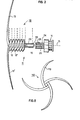
- the construction of each of the page-turning units is more particularly illustrated in Fig. 2, and is therein designated 10. It includes a page-loading section 11 formed with two parallel, helical recesses or grooves 12, 12', each terminating in an arm 13, 13' of substantially crescent shape.
- Each unit 10 further includes a sprocket wheel 14 at its opposite end for rotating the unit about an axis 15.
- each of the page-turning arms extends in the radial direction from the axis of rotation 15 with its crescent shape providing an outer surface of convex configuration, and an inner surface of concave configuration.
- the convex outer face of each arm engages the pages on one side of the book center-line for turning the pages in one direction
- the concave inner face of each arm engages the pages on the other side of the book center-line for turning the pages in the opposite direction.
- each unit 10 is made of two parts, namely: one part including the helical recesses 12, 12' and radial arms 13, 13'; and a separable part including the sprocket 14.
- the first part terminates in a cylindrical pin 20 formed with an axial bore 22, and is telescopically received within the second part in the form of an annular sleeve 24 fixed to the sprocket wheel 14.
- Sleeve 24 is formed with an axially-extending pin 26 received within bore 22 of pin 20.
- the two parts are fixed in the desired position by a threaded fastener 28, and are keyed to each other against rotation, e.g. by bore 22 and pin 26 both being of square cross-section.
- the holder 2 of the illustrated page-turning device includes a bottom horizontal leg 30 for supporting the book 4, and a backing member 32 (Fig. 3) forming a backing wall for supporting the back of the book.
- the holder includes an arm 34 pivotably mounted on the horizontal leg 30 in front of the center of the backing member 32 and engageable with the book 4 along its center-line 5 for clamping the book between it and the backing member.
- Arm 34. is illustrated in Fig. 3 as being in its open (horizontal) position for receiving the book 4, this arm being pivotable to a vertical position to engage the book along its center-line 5, and thereby to firmly clamp the book between it and backing member 32 of the holder.
- Fig. 3a illustrates a preferred modification in the construction of the page-turning units, therein designated 10ma, 10mb.
- the two helical recesses 12m, 12m' connecting the page-turning arms 13m, 13m' of each unit to its annular recess (corresponding to 15 in Figs 2 and 3) for receiving the non-pre-loaded pages of the book are open and have a pitch larger than the remainder of the helical recesses.
- Such an arrangment permits the helical recesses to self-load with one of the non-pre-loaded pages, during each page-turning operation, so that the device can continue to operate even when all the pre-loaded pages have been turned.
- the illustrated page-turning device further includes a pair of retainer arms, 36a, 36b, at the outer ends of the pages on opposite sides of the book center-line. These retainer arms are operated by the drive to retain the book in its open condition.
- the helical recesses 12, 12' on each of the page-turning units 10 are provided for pre-loading the book pages to be turned, When these helical recesses are omitted, it is desirable to include page-arcing means cooperable with the arms of the page-turning device to arc the pages and thereby to assure that the arms of these units will engage the under face of each page to be turned.
- the latter page-arcing means comprises a pair of fingers 38a, 38b engageable with the outer end of each of the two opened pages at a point adjacent to its lower horizontal edge supported on ledge 30, which fingers are movable towards the book center-line, for arcing the respective page; and a further pair of fingers 40a, 40b each engageable with the opened page at a point thereof between the point of engagement of fingers 38a, 38b and the book center-line 5, for retaining the page in place during the above-described inner movement of the fingers 38a, 38b in order to produce an arcing of the page. Fingers 40a, 40b can be omitted in many cases, as will be described below.
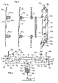
- Fig. 4 The drive for moving all the foregoing elements is schematically illustrated in Fig. 4, wherein it will be seen that the foot pedal 8 is coupled, by a link 50 extending through the stand 6, to mechanism disposed within a housing 52 at the upper end of the stand 6.
- the latter mechanism includes a selector knob 54 which may be manually moved to one of two positions in order to preselect the direction of page-turning.
- moving knob 54 to the "LR" position illustrated in Fig. 1 effects a turning of the pages in the left-to-right direction
- moving knob 54 to the "RL" position effects a turning of the pages in the right-to-left direction.
- selector knob 54 includes a coupling element 54' positionable, according to the position of the knob, to couple either a first stem 56a, or a second stem 56b, to link 50 of the foot pedal drive 8, so that the selected stem is depressed, against the action of its spring 58a, 58b, by the depression of the foot pedal 8.
- Link 50 is also coupled to the two retainer arms 36a, 36b, so as to open both retainer arms when the foot pedal 8 is depressed at the beginning of a page-turning operation, and to reclose the arms when the pedal is released at the end of a page-turning operation.
- the coupling between link 50 and the retainer arms 36a, 36b is schematically shown in Fig.
- first belt 60 fixed at one end to the upper end of stem 50, and at the opposite end to a drum 62 on which it is windable, and two further belts 64 each fixed at one end to drum 62 and at the opposite end to two pulleys 66 coupled to the two above-mentioned retainer arms 36a, 36b, the latter being spring-urged to arm-closed positions illustrated in Fig. 4.
- the two depressable stems 56a, 56b are each coupled to the sprocket 14a, 14b of its respective page-turning unit 10a, lOb, via a mechanism, schematically illustrated in Fig. 4, as including a pulley belt 70a, 70b fixed at one end to the respective stem 56a, 56b; a rack 72a, 72b fixed to the opposite end of the pulley; and an intermediate gear 74a, 74b interposed between each rack 72a, 72b and its sprocket wheel 14a, 14b.
- each rack 72a, 72b are normally retained in their illustrated outermost positions by springs 76a, 76b; but each rack, as selected by selector knob 54, is movable inwardly towards the book center-line 5 upon depression of the foot pedal 8 to rotate its respective sprocket wheel 14a, 14b. Both sprocket wheels are coupled together by a belt 78 so that the rotation of one will also effect the rotation of the other in the same direction; but the direction in which both are rotated by the depression of the foot pedal 8 depends on the position of the direction selector knob 54.
- the intermediate gears 74a, 74b coupling the racks 72a, 72b to their respective page-turning units 10a, lOb are each rotatably mounted within an elongated slot 80a, 80b, and are each normally urged, by a spring 82a, 82b, out of engagement with their respective sprocket wheels.
- the rack when one of the racks (e.g., 72a) is moved inwardly by the depression of foot pedal 8, the rack also moves its gear (e.g., 74a) towards its respective sprocket wheel (e.g., 14a), whereby the gear becomes effective to couple the moved rack to the sprocket wheel; but as soon as the rack has completed its inward (driving) stroke and starts to return (outwardly) to its normal position, its gear moves away from the sprocket wheel, thereby decoupling the latter from the rack during this return stroke.
- gear e.g., 74a
- the two fingers 38a, 40a are coupled to their respective rack 72a such that when the rack is actuated, the two fingers are moved in synchronism to produce an arc in the page to be turned, in-order to facilitate the entry of the respective page-turning arm (e.g. l3ma of Fig. 3a) under the page to be turned at the beginning of the page-turning operation.
- Both fingers 38a and 40a are coupled to their respective rack 72a by a coupling schematically indicated at 84a and 86a.
- the arc-producing finger 38a In order to permit the arc-producing finger 38a to accommodate different sized books, it preferably is mounted on an arm 88a (see Fig. 3) which is adjustable by loosening a threaded fastener 90a, to permit it to be preset with respect to the book center-line 5 according to the size of the book to be clamped to the holder.
- a similar arrangement producing a similar operation is provided with respect to fingers 38b and 40b coupled to rack 72b so as to produce an arc in the opposite page upon the depression of foot pedal 8 when the direction selector 54 is set to effect a right-to-. left turning of the pages.
- the fingers 38a, 38b, as well as 40a, 40b are made of transparent plastic.
- Fig. 5b illustrates the operation of the page-turning unit 10b to effect a right-to-left turning of the pages
- the diagrams of Figs. 6a-6d illustrate the movement of the fingers 38b and 40b during this operation; this operation is produced when the direction selector 54 is set to the "RL" (Fig. 1) position and the foot pedal 8 is depressed.
- the two retainer arms 36a, 36b, and the page-arcing fingers 38a, 38b and 40a, 40b are all in their closed positions spring-pressed against the open pages of the book.
- rack 72b begins to move inwardly towards its sprocket wheel 14b.
- finger 38b begins to move inwardly towards the book center-line. This causes the page to arc, as shown in Fig. 6b, permitting the page-turning arm 13b to enter the space between the upper arced page and the underlying page.
- both fingers 40b and 38b disengage from the page (Fig. 6c), permitting the arm to start to turn the page toward the book center-line.
- inner finger 40b returns to engage the underlying page (Fig.
- the retaining arms 36a, 36b move out of engagei. ment with the book pages at the beginning of the page-turning operation, and return into engagement with them at the end of the page-turning operation.
- both units 10a, 10b may therefore be used for turning the pages in either direction, the direction being selected by the selector 54.
- the bi-directional turning of the pages can also be effected by the use of only one unit, 10a or lOb, together with the page-arcing fingers 38a or 38b.
- the page-arcing finger 38b can be actuated as described above, i.e. counter-clockwise, in order to arc each page an that part (right part in Figs. 5a-5c and Fig. 6a-6d) of the book center-line 5 in order to enable the outer convex surface of the respective arm 13b to engage the page and to turn it, the arm in this case being extended so as to project substantially past the book center-line and thereby to complete the page-turning operation itself.
- unit 10b would be rotated in the opposite direction (i.e., clockwise) and would cooperate with the page-arcing finger 38a on the opposite side (left) of the book center-line, the latter arcing the page at the beginning of the page-turning operation to assure that the concave inner face of the arm engages the page to be turned and turns it during the continued rotation of the unit 10b.
- fingers 40a, 40b may be omitted, in which case the arcing of the respective page would between the resepctive fingers 38a, 38b and the book center-line 5.
- the device illustrated in Figs. 1-4 is particularly useful for clamping to an existing stand 6, or to another support, this being effected by the use of a pair of clamping fasteners 90.
- the device can be built into a stand, this being shown at 2' in Fig. 7.
- the stand 2' illustrated in Fig. 7 is of the collapsible type, and is attachable to the vertical standard by a clamping bar 95.
- each of the two page-turning units as including two radial arms of crescent shape located at opposite sides of the units, so that each unit need be rotated only one-half revolution to effect a complete page-turning operation.
- each unit may include only one such page-turning arm, in which case it would require a complete 360° rotation for a page-turning operation; or it could include a larger number of arms to correspondingly decrease the rotation needed in order to effect a turning of a page.
- Fig, 8 illustrates such a unit, generally designated 110, as including four such radiating arms 113, equally spaced about the circumference of the rotational axis of the unit. It will be appreciated that a four-arm unit as illustrated in Fig. 8 will require but a one-fourth revolution to turn a page.
Landscapes
- Tables And Desks Characterized By Structural Shape (AREA)
Applications Claiming Priority (4)
| Application Number | Priority Date | Filing Date | Title |
|---|---|---|---|
| IL65155A IL65155A0 (fr) | 1982-03-03 | 1982-03-03 | |
| IL65155 | 1982-03-03 | ||
| IL66007A IL66007A (en) | 1982-06-08 | 1982-06-08 | Page-turning device |
| IL66007 | 2020-11-26 |
Publications (1)
| Publication Number | Publication Date |
|---|---|
| EP0087774A1 true EP0087774A1 (fr) | 1983-09-07 |
Family
ID=26321008
Family Applications (1)
| Application Number | Title | Priority Date | Filing Date |
|---|---|---|---|
| EP83101847A Ceased EP0087774A1 (fr) | 1982-03-03 | 1983-02-25 | Dispositif pour tourner des pages |
Country Status (1)
| Country | Link |
|---|---|
| EP (1) | EP0087774A1 (fr) |
Cited By (2)
| Publication number | Priority date | Publication date | Assignee | Title |
|---|---|---|---|---|
| EP1559343A4 (fr) * | 2002-10-18 | 2006-07-26 | Fujimiyaseisakusho Co Ltd | Machine a lire |
| CN112040081A (zh) * | 2020-09-07 | 2020-12-04 | 杭州海洋电脑制版印刷有限公司 | 一种数码扫描机 |
Citations (8)
| Publication number | Priority date | Publication date | Assignee | Title |
|---|---|---|---|---|
| DE63711C (de) * | E. R. STEINER in Hamburg, Grindelallee 76 | Notenblattwender mit zwei die Notenblätter aufnehmenden Schrauben | ||
| GB191229630A (en) * | 1912-12-24 | 1913-11-06 | Herbert Noel Hales | Improvements in or relating to Leaf Turners. |
| US2508913A (en) * | 1947-11-17 | 1950-05-23 | Gorlenko Leonid | Device for mechanically turning pages of books |
| FR1197237A (fr) * | 1958-06-13 | 1959-11-30 | Appareil pour tourner automatiquement les pages d'un livre | |
| US3174242A (en) * | 1961-11-28 | 1965-03-23 | Stanislaw D Degorski | Page turner |
| US3277596A (en) * | 1964-04-20 | 1966-10-11 | Shachar Avi | Mechanical page-turner |
| BE685324A (fr) * | 1966-08-10 | 1967-01-16 | ||
| FR2482009A1 (fr) * | 1980-05-09 | 1981-11-13 | Villeneuve D Ascq Lions Club | Procede pour manoeuvrer des feuilles de petite dimension et dispositif pour tourner automatiquement ou semi-automatiquement les feuilles d'un ensemble de feuilles reliees mettant en oeuvre le procede |
-
1983
- 1983-02-25 EP EP83101847A patent/EP0087774A1/fr not_active Ceased
Patent Citations (8)
| Publication number | Priority date | Publication date | Assignee | Title |
|---|---|---|---|---|
| DE63711C (de) * | E. R. STEINER in Hamburg, Grindelallee 76 | Notenblattwender mit zwei die Notenblätter aufnehmenden Schrauben | ||
| GB191229630A (en) * | 1912-12-24 | 1913-11-06 | Herbert Noel Hales | Improvements in or relating to Leaf Turners. |
| US2508913A (en) * | 1947-11-17 | 1950-05-23 | Gorlenko Leonid | Device for mechanically turning pages of books |
| FR1197237A (fr) * | 1958-06-13 | 1959-11-30 | Appareil pour tourner automatiquement les pages d'un livre | |
| US3174242A (en) * | 1961-11-28 | 1965-03-23 | Stanislaw D Degorski | Page turner |
| US3277596A (en) * | 1964-04-20 | 1966-10-11 | Shachar Avi | Mechanical page-turner |
| BE685324A (fr) * | 1966-08-10 | 1967-01-16 | ||
| FR2482009A1 (fr) * | 1980-05-09 | 1981-11-13 | Villeneuve D Ascq Lions Club | Procede pour manoeuvrer des feuilles de petite dimension et dispositif pour tourner automatiquement ou semi-automatiquement les feuilles d'un ensemble de feuilles reliees mettant en oeuvre le procede |
Cited By (2)
| Publication number | Priority date | Publication date | Assignee | Title |
|---|---|---|---|---|
| EP1559343A4 (fr) * | 2002-10-18 | 2006-07-26 | Fujimiyaseisakusho Co Ltd | Machine a lire |
| CN112040081A (zh) * | 2020-09-07 | 2020-12-04 | 杭州海洋电脑制版印刷有限公司 | 一种数码扫描机 |
Similar Documents
| Publication | Publication Date | Title |
|---|---|---|
| US4463651A (en) | Page-turning device | |
| US4936034A (en) | Reading stand with page turning mechanism | |
| GB2261860B (en) | Steering apparatus with variable steering angle ratio for pitman arm steering mechanism | |
| US2755580A (en) | Page turning device | |
| EP1892081A3 (fr) | Presse | |
| US5695308A (en) | Spiral binding method and apparatus | |
| US5878643A (en) | Curl type sandwich automatic cutting device | |
| MX9204373A (es) | Sujetador intercambiable para uso en una maquina de coser. | |
| US4160334A (en) | Reversible page turner | |
| EP0087774A1 (fr) | Dispositif pour tourner des pages | |
| US20050120601A1 (en) | Automatic page turner with belt drive element | |
| CA2008048A1 (fr) | Dispositif de mise en place du papier | |
| FR2688022B1 (fr) | Dispositif d'arret automatique pour l'entrainement motorise electrique de porte, volet, store ou similaire. | |
| JPH10137045A (ja) | 譜面台または書見台用器具 | |
| DE1660886C3 (de) | Einrichtung zur Drehzahlsteuerung eines Nähmaschinenmotors | |
| US5370468A (en) | Dust cover assembly for computer keyboard | |
| US3030924A (en) | Electrically and manually operable line indicator for copy holders | |
| US5419668A (en) | Adjustable binder stop | |
| FR2506184A1 (fr) | Mecanisme de recherche de dossier | |
| DE3519849C1 (de) | Blindstichnaehmaschine | |
| FR2380970A1 (fr) | Dispositif pour le prelevement de feuillets dans un magasin, dans des machines de conditionnement | |
| CA1157833A (fr) | Dispositif de reglage du tarif pour machine d'affranchissement | |
| WO1993022144A1 (fr) | Dispositif de pressage destine a une machine de brochage | |
| AU1187692A (en) | A document, in particular a credit instrument, able to reveal forgeries | |
| US2942373A (en) | Rotary storage file |
Legal Events
| Date | Code | Title | Description |
|---|---|---|---|
| PUAI | Public reference made under article 153(3) epc to a published international application that has entered the european phase |
Free format text: ORIGINAL CODE: 0009012 |
|
| AK | Designated contracting states |
Designated state(s): AT BE CH DE FR GB IT LI NL SE |
|
| 17P | Request for examination filed |
Effective date: 19840306 |
|
| STAA | Information on the status of an ep patent application or granted ep patent |
Free format text: STATUS: THE APPLICATION HAS BEEN REFUSED |
|
| 18R | Application refused |
Effective date: 19860505 |