EP0087883A2 - Fusil à air comprimé ainsi que sa munition - Google Patents
Fusil à air comprimé ainsi que sa munition Download PDFInfo
- Publication number
- EP0087883A2 EP0087883A2 EP83300762A EP83300762A EP0087883A2 EP 0087883 A2 EP0087883 A2 EP 0087883A2 EP 83300762 A EP83300762 A EP 83300762A EP 83300762 A EP83300762 A EP 83300762A EP 0087883 A2 EP0087883 A2 EP 0087883A2
- Authority
- EP
- European Patent Office
- Prior art keywords
- valve
- cylinder
- casing
- spring
- thrust
- Prior art date
- Legal status (The legal status is an assumption and is not a legal conclusion. Google has not performed a legal analysis and makes no representation as to the accuracy of the status listed.)
- Ceased
Links
Images


Classifications
-
- F—MECHANICAL ENGINEERING; LIGHTING; HEATING; WEAPONS; BLASTING
- F41—WEAPONS
- F41B—WEAPONS FOR PROJECTING MISSILES WITHOUT USE OF EXPLOSIVE OR COMBUSTIBLE PROPELLANT CHARGE; WEAPONS NOT OTHERWISE PROVIDED FOR
- F41B11/00—Compressed-gas guns, e.g. air guns; Steam guns
- F41B11/60—Compressed-gas guns, e.g. air guns; Steam guns characterised by the supply of compressed gas
- F41B11/62—Compressed-gas guns, e.g. air guns; Steam guns characterised by the supply of compressed gas with pressure supplied by a gas cartridge
-
- F—MECHANICAL ENGINEERING; LIGHTING; HEATING; WEAPONS; BLASTING
- F41—WEAPONS
- F41B—WEAPONS FOR PROJECTING MISSILES WITHOUT USE OF EXPLOSIVE OR COMBUSTIBLE PROPELLANT CHARGE; WEAPONS NOT OTHERWISE PROVIDED FOR
- F41B11/00—Compressed-gas guns, e.g. air guns; Steam guns
- F41B11/70—Details not provided for in F41B11/50 or F41B11/60
- F41B11/72—Valves; Arrangement of valves
- F41B11/723—Valves; Arrangement of valves for controlling gas pressure for firing the projectile only
-
- F—MECHANICAL ENGINEERING; LIGHTING; HEATING; WEAPONS; BLASTING
- F42—AMMUNITION; BLASTING
- F42B—EXPLOSIVE CHARGES, e.g. FOR BLASTING, FIREWORKS, AMMUNITION
- F42B6/00—Projectiles or missiles specially adapted for projection without use of explosive or combustible propellant charge, e.g. for blow guns, bows or crossbows, hand-held spring or air guns
- F42B6/10—Air gun pellets ; Ammunition for air guns, e.g. propellant-gas containers
-
- Y—GENERAL TAGGING OF NEW TECHNOLOGICAL DEVELOPMENTS; GENERAL TAGGING OF CROSS-SECTIONAL TECHNOLOGIES SPANNING OVER SEVERAL SECTIONS OF THE IPC; TECHNICAL SUBJECTS COVERED BY FORMER USPC CROSS-REFERENCE ART COLLECTIONS [XRACs] AND DIGESTS
- Y10—TECHNICAL SUBJECTS COVERED BY FORMER USPC
- Y10T—TECHNICAL SUBJECTS COVERED BY FORMER US CLASSIFICATION
- Y10T403/00—Joints and connections
- Y10T403/67—Thimble: screw or cam
Definitions
- This invention concerns improvements in or relating to guns and ammunition for such guns adapted to utilise air or another gas at high pressure to propel missiles.
- a form of ammunition which comprises a hollow outer casing, a pressure cylinder within the casing, valve means at one end of the cylinder, a missile located in a mouth at a nose end of the casing, the pressure cylinder being slidable within the casing to cause the valve means to open and permit compressed air, contained in the cylinder, to flow from the cylinder to the mouth of the casing to expel the missile.
- the ammunition could be recharged with compressed air and a new missile, so as to be readily re-useable.
- the ammunition was designed for use in a firearm, with temporary modification of the latter to provide a barrel sleeve and a blunt firing pin, or for use in a similar weapon permanently adapted only to accept such ammunition to enable missiles of air gun pellet form to be employed for qualification as an air gun and not as a firearm under the Laws of certain countries.
- the present invention provides apparatus, for firing missiles, comprising a gun and a replaceable cartridge assembly_, the cartridge assembly including a casing having a hollow nose, a pressure cylinder slidably located in the casing, and valve means normally biassed by a valve spring in the cylinder to close a gas discharge path from the interior of the cylinder to the hollow nose, which valve means is openable by forcible movement of the cylinder towards the hollow nose;
- the gun comprises a seating at a breech end of a barrel, a breech, a breech block assembly, a firing spring which acts on an inertia member which is releasable by a trigger mechanism;
- the breech block assembly includes a thrust member biassed in a direction towards the seating by a centring thrust spring for thrusting the cartridge assembly towards the barrel to thrust the hollow nose against the seating when the breech block assembly is moved into a firing position whilst the cartridge assembly is in the breech.
- a missile is preferably connected to or located in the hollow nose, so that the combination of the missile and the cartridge assembly serves as a round of ammunition.
- the missile may be of any suitable form, but for shooting practise and amateur use it is intended that the missile will be an air gun pellet, as such pellets are readily available at low cost, and the hollow nose is preferably designed to house such a pellet.
- the apparatus of the invention reduces many of the disadvantages discovered during the trials hereinbefore mentioned.
- the invention offers a reduction of the problems which arose from slight dimensional variations between particular cartridge assemblies, and improves ballistic accuracy.
- the thrust member preferably constitutes a blunt firing pin which is slidably carried by a breech block of the breech block assembly, so that the firing pin is movable between predetermined limits relative to the breech block, and the inertia member is arranged to drive the firing pin towards the breech until one of said limits is reached.
- the centring thrust spring acts via the firing pin and the cylinder upon the casing to engage the hollow nose with the seating when the breech is closed by the breech block assembly, and this action confers greatly improved performance and enables most of said disadvantages to be avoided at little production cost.
- the thrust of the thrust spring upon the cylinder is preferably greater than the thrust of the bias applied by the valve spring upon the valve means, so that after firing the valve means is held open by the thrust of the thrust spring until the breech is opened.
- the mass and permitted distance of movement of the inertia member and the thrust of the firing spring are preferably such as to impart to the inertia member, upon release of the latter by the trigger mechanism, kinetic energy which is equated with the energy (impulse) required to open the valve means to allow at least a major proportion of the gas in the cylinder to be discharged when the cylinder is charged to a predetermined pressure, so as to minimise deflection of the gun from a nominal aimed position upon firing.
- This equating of the kinetic energy with the valve opening energy gives an additional advantage of preventing the valve being opened if the cylinder pressure is too high, and of restricting the amount of gas discharged if the cylinder pressure is fractionally above the predetermined pressure.
- the invention includes the gun per se, and in particular provides a gun for discharging compressed gas powered cartridge assemblies, the gun comprising a seating at a beech end of a barrel, a breech, a breech block assembly, a firing spring which acts on an inertia member which is releasable by a trigger;
- the breech block assembly includes a thrust member biassed in a direction towards the seating by a centring spring for thrusting a cartridge assembly towards the seating when the breech block assembly is moved into a firing position whilst the cartridge assembly is in the breech; wherein said thrust member is a firing pin arranged to be actuable by the inertia member.
- the inertia member, firing spring and beech block assembly preferably form parts of a bolt assembly, the breech block assembly comprising a breech block fixedly secured to a hollow bolt body to hinder removal of the inertia member and firing spring.
- the invention further includes the cartridge assembly per se in which the hollow nose is complementary to the seating of the gun.
- an improved cartridge assembly comprising a casing having a hollow nose, a pressure cylinder slidably located in the casing, and valve means normally biassed by a valve spring in the cylinder to close a gas discharge path from the interior of the cylinder to the hollow nose, which valve means is openable by forcible movement of the cylinder towards the hollow nose, characterised in that the gas discharge path is provided by a hollow valve abutment member having a cylindrical portion which extends from a head of the valve abutment member through an end wall of a body of said casing and into a valve end portion of the cylinder to abut a valve member in the cylinder, the head of the valve abutment member being hollow and being releasably clamped between said end wall and a nosepiece of the casing, which nosepiece defines the hollow nose and is releasably secured to the body of the casing.
- the cylindrical portion of the valve abutment member and the valve end portion of the cylinder are self aligning about a common axis; and the nosepiece and valve abutment member are removable.
- the nosepiece defines a mouth for an air gun pellet
- the pellet can be loaded into the mouth from the rear of the mouth so that the skirt of the pellet is located between the head of the valve abutment member and the nosepiece, so as to avoid damage to the skirt.
- the main advantage of this improved cartridge assembly arises from the interrelationship between the gun and the cartridge assembly.
- the concept underlying the improved gun is extended in the improved cartridge to give improved performance which arises because the action, of the thrust spring brings the self-aligning capability of the cartridge assembly into effect, thereby minimising the effects of manufacturing tolerances and other variables which otherwise detract from the performance of the apparatus.
- the present invention also provides improved air pump apparatus comprising a pump cylinder, a piston in said cylinder and movable to abut an outlet end of the cylinder by means of an actuating mechanism for compressing air in the cylinder, characterised in that a cylindrical charging tube projects from said outlet end, in that cartridge support means is provided concentric with said charging tube for supporting a cartridge during charging, in that said actuating mechanism is manually actuable and provides an increasing mechanical advantage as the piston is moved to abut said outlet end; and in that means is provided to limit the maximum pressure to which air can be compressed by the pump.
- Said cartridge support preferably comprises a female thread in which a male nosepiece retaining thread on the casing is engageable after removal of the nospiece and valve abutment member, and preferably further comprises a hollow guide member for aligning the cartridge assembly with the charging tube as the cartridge assembly is inserted into the guide member.
- This form of support provides accurate location of the cartridge assembly with respect to the charging tube, and protects the latter from impact damage and contamination by dust.
- the apparatus for firing missiles may include the improved air pump apparatus.
- the improved cartridge assembly permits recharging using the improved pump apparatus by means of a method provided in accordance with the invention, which method comprises the steps of:-
- Said tube is preferably provided with peripheral sealing means to engage said in valve end portion.
- the invention includes the combination of the improved cartridge assembly and said pump apparatus.
- the improved cartridge assembly has the advantage that it can be constructed so that many of the parts of the assembly are common to a wide range of cartridge assemblies for a range of uses or purposes, e.g. by varying only the nosepiece.
- the body of the casing preferably comprises a main plastics body moulding incorporating said end wall, together with a plastics end ring bonded, e.g. welded, to the main body moulding remote from said end wall to retain the cylinder permanently within the body.
- the cylinder is preferably made in two parts from lightweight metal such as aluminium alloy, the parts being joined together in a pressure tight manner after insertion of the valve spring and valve member.
- the closure plug preferably provides an impact resistant projection which extends into the end ring, and preferably forms part of or is adapted to serve as volume limiting means for restricting the capacity of the cylinder.
- the cylinders and/or casings are preferably coded by colour or markings to denote cylinder capacity.
- the valve means preferably comprises a valve seating provided by or on said valve end portion, a valve member of poppet form movable relative to the seating, and a plastics or elastomeric sealing member carried by the valve member; and said valve means is preferably characterised in that:-
- valve seating and face ensure that, during closing of the valve means, the valve member is guided by the seating so as to become co-axially aligned with the valve seating, so that,
- valve face and seating are preferably polished to taper at identical angles, and are preferably defined by metal, ceramics or hard heat resistant plastics surfaces.
- cartridge assembly 10 and a gun 14 which in combination constitute apparatus for firing missiles, and a pump 18 which together with said apparatus and missiles constitutes a weapons system.
- the missiles are air gun pellets 11 which are loaded into the cartridge assemblies 10 to form rounds of ammunition, one of which rounds is shown in FIGURE 1.
- the cartridge assembly 10 comprises a casing 12 and a lightweight metal pressure cylinder 13, which incorporate valve means.
- the casing 12 comprises a hollow plastics main boay moulding 2U and an end ring 21 permanently bonded to a base end of the moulding 20 to constitute a body 20, 21 of the casing; and comprises a detachable hollow moulded plastic nosepiece 22 and a hollow metal valve abutment member 23 (which member 23 constitutes part of the valve means).
- the nospiece 22 defines a mouth 24 in which the pellet 11 is located so that a skirt of the pellet 11 is located between the nosepiece and a flange head 25 of the abutment member; and the nosepiece is screw threaded to engage an externally threaded end portion 26 of the moulding 20 so as to clamp the head 25 against an annular internal end wall 27 of said portion 26.
- the abutment member 23 includes a cylindrical portion 28 which extends through a central orifice in said end wall 27 into the interior of the body 20,21 and is apertured to provide ports 29 remote from the head 25.
- the pressure cylinder 13 is permanently retained in the body 20,21 by the end ring 21, and comprises a hollow main pressure member 30 having a metal closure plug 31 permanently bonded into a base end of the member 30 after a valve spring 32 and valve assembly of the valve means have been inserted into the member 30.
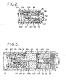
- the other end of the member 30 provides a wall 34 which provides a conical valve seating 341 (FIGURE 2), and a cylindrical extension 35 into which the cylindrical portion 28 extends.
- the base end of the member 30 may incorporate the closure 31; whilst the other end is separately made and secured to the member 30 to provide the extension 35.
- the valve assembly comprises a valve member 33 having a tapered valve face 301 and a stem 302, an elastomeric seal 303 around the stem 302 and a backing washer 304 which is engaged by the spring 32.
- the stem 302 is pushed into one end of the spring 32 to connect the latter and the valve assembly.
- the face 301 abuts and substantially sealingly engages part of the seating 341 to provide a surface to surface junction therebetween.
- the seal 304 abuts the part of the seating around the head so as to engage one end of the junction to seal the latter.
- the gas pressure tends to deform the sealing member but the intimate surface to surface contact at the junction serves to prevent the sealing member being extruded through said junction.
- the plug 31 has an impact resistant base 36 which extends into the ring 21, and has a recess 37 which serves as or as part of capacity limiting means.
- the recess may be used as a socket to receive a body, e.g. as indicated in broken lines at 38, to reduce the effective internal volume of the cylinder.
- the cylinder 13 is charged with compressed air to a pressure within a predetermined range.
- the gun 14 (FIGURE 3) comprises a stock (not shown) to which is fitted a main tube 40 provided at one end with a trigger mechanism 41 and at the other end with a breech member 42 in which a rear end portion of a barrel 43 is secured so as to provide a conical seating 44 at one end of the breech chamber 45.
- the tube 40 houses a bolt assembly which comprises a hollow bolt 46, an inertia member 47 slidably located in the bolt so that a stepped rear end portion 48 extends from the rear of the bolt for engagement by the trigger mechanism, a firing spring 49 located around the inertia member 47 within the bolt, and a breech block assembly 50 fixedly secured at the front of the bolt 46 to retain the member 47 and spring 49 in the bolt.
- the assembly 50 comprises a breech block 51, a toothed extractor 52 biassed . towards the bolt axis by an extractor spring 53, a firing pin 54 biassed.towards the breech by a thrust spring 55 located in the breech block.
- the firing pin 54 has a rear head 56 outside the rear of the breech block 51 and a front head 57 which is screwed onto the firing pin 54 so as to compress the thrust spring 55 so that the rear head 56 normally abuts the rear of the breech block.
- the main tube is slotted to provide an ejection opening 60 and a side slot 61 through which a bolt actuating handle 62 extends in known manner.
- the bolt actuating handle 62 is raised to clear a known form of stop 61A at the front of the side slot 61 and is retracted along the slot 61 to move the bolt rearwards as indicated by arrow A until the rear of the bolt 46 hits a stop 63 on the trigger mechanism and until the stepped portion 48 of the inertia member 47 engages and is held by a sear 64 of the trigger mechanism 41.
- the retraction of the bolt 46 clears the opening 60 to allow the cartridge assembly 10 to be partially inserted nose first into the open breech chamber 45.
- the handle 62 is then thrust forwards and re-engaged with the stop to move the bolt, breech block assembly and cartridge assembly to the condition in which they are shown in FIGURES 1 and 3 whilst causing the firing spring 49 to be compressed between a head 65 of the inertia member 47 (which is still held by the sear 64) and the rear of the bolt 46.
- the head 57 of the firing pin 54 engages the base 36 of the plug 31 and thrusts the cylinder forwards until, as shown in FIGURE 1, the valve member 33 abuts and engages in the end of the portion 28 of the abutment member 22 and thrusts the cartridge assembly forwards until the nosepiece 22 is seated in the seating 44; and thereafter during the last part of the forward movement the base end of the cartridge assembly enters into a socket 66 in the front of the breech block so as to cause the extractor 52 to engage in an extraction groove 67 in the end ring 21, and so as to push the firing pin 54 back relative to the breech block so that the rear head 56 is moved clear of the rear of the breech block.
- the sear moves in the direction of arrow C to release the inertia member which is propelled forwards (arrow D) to strike the firing pin thereby causing the latter to move the cylinder forwards relative to the valve member and abutment member to the condition shown in FIGURE 2 so as to permit the compressed air to discharge from the cylinder 13 into the mouth via the abutment member and thus propel the missile through the barrel.
- the ports 29 and the interior of the abutment member 23 provide a discharge passage for the air from the interior of the cylinder to the mouth.
- the sequence is then repeated to reload and fire the gun, but during the rearwards movement of the bolt, the discharge cartridge assembly is drawn to the ejection opening 60 by the extractor 52; and the thrusts of the valve and thrust springs 32 and 55, or one of said thrusts depending upon various factors, tends to pivot the cartridge assembly upwards about a fulcrum provided by the extractor so that, when the nosepiece 22 clears the breech, the cartridge assembly is swung upwards through the opening 60 and in so doing disengages the end ring from the breech block assembly.
- the pump 18, FIGURES 4 and 5 comprises a pump cylinder 80, a piston assembly 81 including a piston head 82 slidable in the cylinder, a drive link 83 pivotally connected between the assembly 81 and a lever 84 pivotally mounted on the cylinder 80, an end member 85 in one end of the cylinder 80 and a holder 86 releasably connected to the end member 85.
- the cylinder 80, link 83 and lever 84 form a mechanism which is arranged so that the mechanical advantage afforded upon the lever 84 being swung increases as the head 82 is moved in the cylinder towards that face 87 of the end member 85 which confronts the head 82 to reach a maximum when the link 83 is parallel with the axis of the cylinder 80; and said mechanism is arranged so that at the point of maximum advantage the head is in face to face contact with the said face 87 so that substantially all the air compressed by the piston is forced into a narrow bore charging passage 87A in the end member 85.
- the end member 85 has a charging tube 88, through which said passage 87A extends, which tube 88 is provided with an "O"-ring seal 89 and is dimensioned to enter the cylindrical extension 35 of the pressure cylinder 13 when the nosepiece 22 and abutment member 23 are removed from the cartridge assembly, so that the seal 89 is effective therebetween, as shown in FIGURE 5.
- the holder 86 is screwed onto the end member 85 so as to hold the cartridge assembly against the end member, and is provided with a vent 90.
- the pump has a mounting clamp 94 secured to the cylinder 80, and the latter has an air inlet port 80A and an external filter 80B.
- a pressure relief passage 95 leading to pressure relief valve means 96 In the piston assembly 81 there is a pressure relief passage 95 leading to pressure relief valve means 96.
- the latter comprises a powerful spring 97 acting on a piston valve member 97A which is located in a double diameter bore 97B and carries a sealing ring 97C.
- the holder 86 is covered during charging by an arched cover 104 pivotally mounted on the pump so as to be swung down by the lever 84 to engage and grip the holder 86 during the first stroke, so that the cover has to be raised manually after pumping to expose the holder for removal of the cartridge.
- the margins of the cover have longitudinal flanges 105 to abut the lever 84, and the cover prevents the lever 84 being swung down more than a few degrees beyond the horizontal.
- FIGURE 6 shows an improved pump and those parts of the pump which are identical with the same parts in the pump shown in FIGURES 4 and 5 are identified by the same reference numerals and will not be described further herein whereas modified parts are indicated by the same reference numerals with the addition of the suffix C.
- the improved pump differs from the pump shown in FIGURE 4 primarily in that:-
- the cartridge assembly is inserted into the holder 86C via the portion 112, the holder being dimensioned internally to serve as a guide effective to substantially align the assembly with the charging tube so that the latter passes cleanly through the central orifice clear of the wall 27; and thereafter the casing 12 is rotated to engage the nosepiece retaining thread 26B in the thread part A to retain the cartridge assembly in position for charging.
- the improved pump also employs the cover 104 dimensioned to cover the exposed portion of the cartridge assembly (indicated in broken lines in FIGURE 6), and embodies other improvements, e.g. the end member 85C (FIGURE 6) has an "0"-ring seal and is engaged by a mounting bolt 114 as well as by the pivot 115 on which the lever 85 (FIGURE 4) is mounted.
- the end member 85C (FIGURE 6) has an "0"-ring seal and is engaged by a mounting bolt 114 as well as by the pivot 115 on which the lever 85 (FIGURE 4) is mounted.
- the improved pump is less expensive to manufacture, is easier to use, and is less easily damaged and contaminated than the pump disclosed in FIGURES 4 and 5.
- the volumetric capacity of the charging passage 87A is much smaller than the capacity of the pump cylinder and the capacity of the pressure cylinder, so that most of the air compressed by the pump is forced into the pressure cylinder, the valve means 33 acting as a non-return valve for the pump and cartridge combination.
- the pressure relief valve means 96 serves to limit pump pressure.
- the piston area of the pump valve member 97A and the rating of the spring 97 are selected so that the spring 97 yields allowing the piston valve member 97A to move back into the piston 82 when said predetermined pressure is reached, thereby initially increasing the effective headspace for the compressed air without allowing compressed air to escape via the passage 95, so as to give time for the compressed air, at said predetermined pressure, to traverse the passage 87A and enter the cylinder 30.
- the cartridge assembly, the gun and the pump have many inherent individual advantages, and the interrelationship therebetween affords further advantages in addition to those mentioned hereinbefore.
- an.improved cartridge assembly casing in accordance with a further aspect of the invention can be made substantially from injection moulded high strength plastics components (except possibly for the valve spring, abutment member, cylinder and valve member) so that a single elongate one of said components serves as a datum for the end portion of the cylinder into which the abutment member extends, and wholly incorporates a wall, shoulder, flange or other positional datum which serves as a stop and guide for said end portion and for the abutment member, and therefore in the region of the valve, all critical tolerances are determined primarily by the injection moulding of this individual component, e.g. the body moulding 20; the other plastics components necessary to form the casing body, e.g.
- the end ring 21 and the nosepiece being secured e.g. ultrasonically or frictionally welded, or screwed to the ends of the individual component 20 remote from or outside said valve region so that the small tolerance variations do not significantly affect said valve region.
- the abutment member is a clearance fit in a central aperture in said positional datum, e.g. the end wall 27, so that it is self aligning with and in said end portion 35 of the cylinder body as it is inserted through the central aperture; and the abutment member is clamped to the side of said positional datum which is remote from the side facing the end portion 35 after said self alignment has taken place.
- the critical tolerances are within the outer casing, and because the assembly is designed to be positionally located in a breech by means of its base and nose end surfaces, the outer peripheral shape of the casing between its end portions is immaterial (provided that the cartridge is narrow enough to be accepted into the breech).
- a range of cartridges can be constructed from standard components of which only the nose pieces, end rings and end plugs need to be varied to suit the breech length and end shapes, and the form of the missile.
- the missile may be separate from the cartridge assembly for prior insertion into the barrel or breech; may be attached to the nosepiece; or may be accommodated in the nosepiece. Considerable cost savings are thus made possible.
- the gun can be made in many forms, e.g. as a pistol by using a reflex bolt type inertia member with a part shaped to reach the rear end of the firing pin, or by using a hammer as the inertia member.
- the barrel is replaceable, upon releasing the screws 91 and 92, so that a barrel suited to a different type of missile can be used.
- breech block assembly 50 described has the advantage that the free axial movement of the cylinder 30 is negated and the cylinder is positioned so that the valve and abutment members 33,29 are in contact prior to firing thus minimising the-mavement and energy necessary to open the valve; and has the advantage that the rear head 56 of the firing pin abuts the breech block 51 after firing to protect the cartridge from excessive thrust from the inertia member 47.
- the gun and cartridge apparatus for firing missiles has several other major advantages which arise from the interrelationship between the gun and the cartridge assembly in which the various forces are equated to limit the energy imparted to the missile.
- the valve means when charged with air or other compressed gas, the valve means is held closed by closure forces comprising:
- This arrangement gives the advantage that the maximum impulse and thus velocity which can be imparted to the missile is strictly predetermined, and attempts to increase said velocity by overpressurising the cartridge will be futile.
- said maximum impulse can be predetermined and varied most easily and inexpensively by any one or more of the following variations:
- the main advantage of this arrangement is that the guns, bolt assemblies and cartridge assemblies can be designed to meet the regulations pertaining in particular countries, and can be stamped, coloured or otherwise marked and identified appropriately, at minimum cost to the manufacturer and user; and the weapons system as described is almost impossible to modify for illegal use unless the user has substantial engineering knowledge and engineering facilities to make modified parts.
- the cartridge assemblies and the guns have the additional advantage that further safeguards against illegal use and unauthorised modification can be, and will be, incorporated at no or slight increase in manufacturing cost.
- the thrust of the thrust spring is greater, e.g. two or three times, the thrust of the valve spring, so that the valve is held open after firing to obtain a complete discharge of gas (at pressures up to the predetermined pressure).
- the valve spring will act to pivot the cartridge out of the ejection opening. Whilst a further increase of the thrust of the thrust spring would reduce the kinetic energy of the inertia member required to actuate the valve, and thus the accelerative forces (which generate recoil actions within the gun), such a further increase could represent a safety hazard.
- gas pressure of about 1 kilogramme per square millimeter (100 atmospheres) or more for charging, but if the valve leaks said pressure could drop to a few atmospheres reducing the aforementioned valve closure forces to the point at which the thrust spring could prematurely fire the missile as the nosepiece touched the breech during loading.
- the thrust spring is only slightly stronger than the firing spring, the missile impulse will be so small that the missile may lodge in the barrel or fall out of the muzzle of the barrel in a harmless manner, because the pressure loss necessary before inadvertent discharge during loading can occur must be so large that very little pressure remains in the cylinder.
- the free length of the firing spring is such that when the head of the inertia member abuts the spring in an unstressed (uncompressed) condition the head is just clear of the rearmost position of the rear head of the firing pin, so that the firing spring cannot contribute to the force of the thrust spring if the bolt is moved forwards with the inertia member 48 disengaged from the sear 64.
- the arrangement has the further advantage that recoil actions and jerking of the gun upon firing are minimised by equating the forces as described, because, at or near to said predetermined pressure, the opening of the valve absorbs (consumes) the kinetic energy of the inertia member and the firing pin supplements the thrust of the thrust spring in resisting the valve closing forces as the gas is discharging.
- the recoil forces are thus substantially unidirectional. This substantially avoids the jerking which arises in many known pump action air guns due to directional reversal of the recoil forces.
- the above mentioned features also enable a simple and inexpensive pump to be employed without incorporating into the pump any valves or elaborate safety devices. If the pump is abused to exceed the pressure limits of the cartridge, the end plug 36 is designed to rupture or break away allowing gas to escape, e.g. via a vent channel 93 in the end ring and the vent 90. Also the end plug may have a recess 136 so that a portion 36A serves as a bursting zone which ruptures at above said predetermined pressure.
- the end plug 36 may be hollow to define a blow out duct 36 B which is normally closed by a plastics coated or plastics backed metal bursting disc 36C held in place by the spring 36, so that the disc 36C bursts at pressures fractionally above the predetermined pressure.
- the main tube and breech member may have a magazine opening, and a magazine for several cartridges may be provided for the gun, in known manner.
- the barrel and breech member may be integral or permanently joined, and the main tube may be permanently joined thereto.
- the external shape of the extension 35 or valve end portion of the cylinder may be varied, as may be the confronting interior surfaces of the casing, e.g. the end wall, but it is preferred to form these shapes so that when the valve is opened a vent path is left to prevent gas being compressed or trapped between said surfaces.
- the cylinder is a clearance sliding fit in the casing so that a sufficient clearance space is left open to permit air to escape from adjacent the end of the extension 35 and along the cylinder to the vent channel 93.
- the vent path is separated from the mouth by a partition constituted by the wall 27 and the head 25, but is connected to the mouth by a slow restricted leakage path via the ports 29.
Landscapes
- Engineering & Computer Science (AREA)
- General Engineering & Computer Science (AREA)
- Toys (AREA)
- Portable Nailing Machines And Staplers (AREA)
Applications Claiming Priority (2)
| Application Number | Priority Date | Filing Date | Title |
|---|---|---|---|
| GB8205875 | 1982-02-27 | ||
| GB8205875 | 1982-02-27 |
Publications (2)
| Publication Number | Publication Date |
|---|---|
| EP0087883A2 true EP0087883A2 (fr) | 1983-09-07 |
| EP0087883A3 EP0087883A3 (fr) | 1983-10-12 |
Family
ID=10528683
Family Applications (1)
| Application Number | Title | Priority Date | Filing Date |
|---|---|---|---|
| EP83300762A Ceased EP0087883A3 (fr) | 1982-02-27 | 1983-02-16 | Fusil à air comprimé ainsi que sa munition |
Country Status (3)
| Country | Link |
|---|---|
| US (1) | US4539969A (fr) |
| EP (1) | EP0087883A3 (fr) |
| GB (1) | GB2116681B (fr) |
Cited By (1)
| Publication number | Priority date | Publication date | Assignee | Title |
|---|---|---|---|---|
| RU2134399C1 (ru) * | 1993-08-16 | 1999-08-10 | Константиа (Интернэшнл) Лимитед | Газовый патрон |
Families Citing this family (20)
| Publication number | Priority date | Publication date | Assignee | Title |
|---|---|---|---|---|
| GB2153983B (en) * | 1982-02-27 | 1986-12-03 | Hilvenna Ltd | Ammunition for air guns |
| EP0158408A3 (fr) * | 1984-02-14 | 1987-01-14 | Hilvenna Limited | Munition en cartouche pour armes portatives |
| GB2193797B (en) * | 1986-08-05 | 1989-12-20 | Stephen Ashley Harper | Air guns. |
| US4729319A (en) * | 1987-02-03 | 1988-03-08 | Edward Orlando | Controlled explosion projectile ejection system |
| GB9002288D0 (en) * | 1990-02-01 | 1990-03-28 | Spencer John R | An improved cocking mechanism |
| NL9100257A (nl) * | 1991-02-14 | 1992-09-01 | Michael Ernest Saxby | Met een gasdrukvulling werkende patroonmunitie. |
| GB2274502A (en) * | 1993-01-23 | 1994-07-27 | Robin Malcolm Chainey | Air gun pellet and cartridge. |
| US5586545A (en) * | 1995-10-02 | 1996-12-24 | Mccaslin; John A. | Compressed gas gun |
| US5706795A (en) * | 1996-07-19 | 1998-01-13 | Gerwig; Phillip L. | Multi-purpose projectile launcher |
| GB2331577A (en) * | 1997-11-25 | 1999-05-26 | Patrick Thomas Barry | Compressed gas powered bullet or shell |
| US5813392A (en) * | 1998-01-03 | 1998-09-29 | Mccaslin; John A. | Compressed gas gun |
| GB2341440A (en) | 1998-09-14 | 2000-03-15 | Michael Ernest Saxby | Blank cartridge for self loading guns |
| US7222573B2 (en) | 2005-04-01 | 2007-05-29 | Pontieri James M | Aerodynamic air gun projectile |
| US7757682B2 (en) * | 2006-10-05 | 2010-07-20 | Crosman Corporation | Magazine assembly for presenting a pressure cartridge to a compressed gas powered device |
| JP5283040B2 (ja) * | 2009-10-14 | 2013-09-04 | マルシン工業株式会社 | 薬莢式エアーガン |
| US8256406B1 (en) * | 2011-06-01 | 2012-09-04 | Kevin Kirkpatrick | Systems and methods for regulating pneumatic gas propulsion |
| HK1161810A2 (en) * | 2012-03-01 | 2012-08-03 | APS Limited | Compressed gas pellets |
| US20150241165A1 (en) * | 2014-02-21 | 2015-08-27 | Air Ordnance Llc | Fluid cartridge powered pellet gun |
| US9605924B1 (en) | 2015-10-22 | 2017-03-28 | John A. McCaslin | Compressed gas gun with improved operating mechanism |
| US11378352B1 (en) * | 2021-01-19 | 2022-07-05 | Crosman Corporation | Gas powered semi-automatic airgun action |
Family Cites Families (12)
| Publication number | Priority date | Publication date | Assignee | Title |
|---|---|---|---|---|
| GB149459A (en) * | 1919-05-22 | 1920-08-19 | William Thomas | Improved mechanical coupling for electric conductors |
| US1517761A (en) * | 1920-04-06 | 1924-12-02 | Reed Roller Bit Co | Coupling for rotary-drill-stem sections |
| US1893033A (en) * | 1931-12-15 | 1933-01-03 | Elliott Core Drilling Company | Rock drill |
| US1996422A (en) * | 1932-03-07 | 1935-04-02 | Hurley Townsend Corp | Cooled and shielded spark plug |
| US2327653A (en) * | 1941-04-23 | 1943-08-24 | Lisle Elmer | Pneumatic cartridge and gun |
| US2815231A (en) * | 1954-02-11 | 1957-12-03 | Wilson John Hart | Threaded nut ring for shaft coupling |
| GB858282A (en) * | 1956-04-25 | 1961-01-11 | Wilmot Kenneth | Improvements in toy guns and cartridges therefor |
| FR1372175A (fr) * | 1963-10-08 | 1964-09-11 | Procédé et dispositif pour obtenir avec une bouche à feu une vitesse initiale variable | |
| US3507562A (en) * | 1967-02-28 | 1970-04-21 | Ichikawa Seisakusho Kk | Rear view mirrors |
| GB1601917A (en) * | 1976-10-28 | 1981-11-04 | Hilvenna Ltd | Ammunition for small arms |
| GB1601918A (en) * | 1977-09-19 | 1981-11-04 | Hilvenna Ltd | Ammunition for small arms |
| US4361093A (en) * | 1978-11-30 | 1982-11-30 | Hilvenna Limited | Ammunition for small arms |
-
1983
- 1983-02-16 EP EP83300762A patent/EP0087883A3/fr not_active Ceased
- 1983-02-16 GB GB08304313A patent/GB2116681B/en not_active Expired
- 1983-02-24 US US06/469,365 patent/US4539969A/en not_active Expired - Fee Related
Cited By (1)
| Publication number | Priority date | Publication date | Assignee | Title |
|---|---|---|---|---|
| RU2134399C1 (ru) * | 1993-08-16 | 1999-08-10 | Константиа (Интернэшнл) Лимитед | Газовый патрон |
Also Published As
| Publication number | Publication date |
|---|---|
| GB2116681A (en) | 1983-09-28 |
| US4539969A (en) | 1985-09-10 |
| GB2116681B (en) | 1986-12-10 |
| GB8304313D0 (en) | 1983-03-23 |
| EP0087883A3 (fr) | 1983-10-12 |
Similar Documents
| Publication | Publication Date | Title |
|---|---|---|
| US4539969A (en) | Cartridge assembly including pressure cylinder slidably located in casing | |
| US4697523A (en) | Compressed gas powered ammunition for guns | |
| US6622610B2 (en) | Gas retarded blowback operating system for pistols and other short barreled weapons | |
| US8191480B2 (en) | Method and apparatus for propelling a pellet or BB using a shock-sensitive explosive cap | |
| US5016536A (en) | Non-lethal practice round for automatic and semiautomatic firearms | |
| US4531458A (en) | Compressed gas powered ammunition for small arms | |
| US7007424B2 (en) | Multi-shot ring airfoil projectile launcher | |
| US6886467B1 (en) | Training cartridge for an automatic rapid-fire weapon | |
| US5438907A (en) | Blank firing adaptor | |
| US4361093A (en) | Ammunition for small arms | |
| GB1601917A (en) | Ammunition for small arms | |
| JP4860983B2 (ja) | 発砲装置 | |
| GB1601918A (en) | Ammunition for small arms | |
| RU2307992C1 (ru) | Боевое пневматическое короткоствольное оружие (варианты) | |
| US4506604A (en) | Cartridge shaped barrel insert | |
| CN113295045A (zh) | 柱状软弹上弹机构及玩具枪 | |
| GB2153983A (en) | Ammunition for air guns | |
| US3416402A (en) | Engine launching device | |
| CA2547395A1 (fr) | Cartouche d'entrainement a faible energie | |
| US2984836A (en) | Firing tool with ammunition, more particularly for use as a pin driving tool | |
| CN217058513U (zh) | 柱状软弹上弹机构及玩具枪 | |
| EP0158408A2 (fr) | Munition en cartouche pour armes portatives | |
| US3355989A (en) | Closed breech rocket gun | |
| US10488164B1 (en) | Firearm system configured to fire a cartridge of reduced length | |
| KR102698531B1 (ko) | 페인트볼 소총용 노리쇠 뭉치 |
Legal Events
| Date | Code | Title | Description |
|---|---|---|---|
| PUAI | Public reference made under article 153(3) epc to a published international application that has entered the european phase |
Free format text: ORIGINAL CODE: 0009012 |
|
| PUAL | Search report despatched |
Free format text: ORIGINAL CODE: 0009013 |
|
| AK | Designated contracting states |
Designated state(s): AT BE CH DE FR GB IT LI NL SE |
|
| AK | Designated contracting states |
Designated state(s): AT BE CH DE FR GB IT LI NL SE |
|
| 17P | Request for examination filed |
Effective date: 19840405 |
|
| STAA | Information on the status of an ep patent application or granted ep patent |
Free format text: STATUS: THE APPLICATION HAS BEEN REFUSED |
|
| 18R | Application refused |
Effective date: 19871023 |
|
| RIN1 | Information on inventor provided before grant (corrected) |
Inventor name: SAXBY, MICHAEL ERNEST |