EP0087896A1 - Flüssigmetallionenquelle - Google Patents
Flüssigmetallionenquelle Download PDFInfo
- Publication number
- EP0087896A1 EP0087896A1 EP83300846A EP83300846A EP0087896A1 EP 0087896 A1 EP0087896 A1 EP 0087896A1 EP 83300846 A EP83300846 A EP 83300846A EP 83300846 A EP83300846 A EP 83300846A EP 0087896 A1 EP0087896 A1 EP 0087896A1
- Authority
- EP
- European Patent Office
- Prior art keywords
- needle
- sheath
- source according
- emitting tip
- source
- Prior art date
- Legal status (The legal status is an assumption and is not a legal conclusion. Google has not performed a legal analysis and makes no representation as to the accuracy of the status listed.)
- Granted
Links
- 229910001338 liquidmetal Inorganic materials 0.000 title claims abstract description 27
- 150000002500 ions Chemical class 0.000 claims abstract description 22
- 229910052751 metal Inorganic materials 0.000 claims abstract description 16
- 239000002184 metal Substances 0.000 claims abstract description 16
- 239000007788 liquid Substances 0.000 description 6
- 239000000843 powder Substances 0.000 description 3
- WHXSMMKQMYFTQS-UHFFFAOYSA-N Lithium Chemical compound [Li] WHXSMMKQMYFTQS-UHFFFAOYSA-N 0.000 description 1
- 229910052792 caesium Inorganic materials 0.000 description 1
- TVFDJXOCXUVLDH-UHFFFAOYSA-N caesium atom Chemical compound [Cs] TVFDJXOCXUVLDH-UHFFFAOYSA-N 0.000 description 1
- 230000006835 compression Effects 0.000 description 1
- 238000007906 compression Methods 0.000 description 1
- 238000000605 extraction Methods 0.000 description 1
- 229910052744 lithium Inorganic materials 0.000 description 1
- 239000000463 material Substances 0.000 description 1
- 150000002739 metals Chemical class 0.000 description 1
- -1 or powdered Substances 0.000 description 1
- 239000007921 spray Substances 0.000 description 1
Images
Classifications
-
- H—ELECTRICITY
- H01—ELECTRIC ELEMENTS
- H01J—ELECTRIC DISCHARGE TUBES OR DISCHARGE LAMPS
- H01J27/00—Ion beam tubes
- H01J27/02—Ion sources; Ion guns
- H01J27/26—Ion sources; Ion guns using surface ionisation, e.g. field effect ion sources, thermionic ion sources
Definitions
- the present invention relates to sources for providing ions of liquid metals and/or charged liquid metal droplets.
- a type of liquid metal ion source or droplet sprayer consists of a pointed needle from the tip of which the liquid metal ions or droplets are emitted.
- the liquid metal is fed to the emitting tip of the needle at a controlled rate by means of capillary and surface tension effects.
- a source for the provision of ions or charged droplets of a metal consisting of a needle having an emitting tip, a reservoir for a metal, ions or charged droplets of which are to be emitted by the source, and a sheath surrounding the needle and from which the needle projects, the sheath serving to convey liquid metal to the emitting tip of the needle at a controlled rate, wherein there is provided means for withdrawing the emitting tip of the needle into the sheath so as to enable the emitting tip of the needle to be immersed in the liquid metal.
- the means for withdrawing the emitting tip of the needle into the sheath may be electromagnetically operated or it can comprise a mechanically operated device.
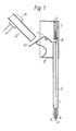
- a needle type liquid metal ion source consists of a pointed needle 1 which extends through a tubular reservoir 2 into a closed metal trough 3 which surrounds the end of the reservoir 2 which is remote from an emitting tip 4 of the pointed needle 1.
- the other end of the reservoir 2 terminates in a length of narrow-bore tubing 5 which forms a sheath 6 surrounding the needle 1 and out of which it normally projects.
- the clearance between the sheath 6 and the needle 1 is such that, coupled with the distance between the end of the sheath 6 and the tip 4 of the needle 1 frof which the emission of material takes place when the needle 1 is in an operative position, either single ions or charged droplets of liquid are emitted, as required.
- a compression spring 7 surrounds the end of the needle 1 which projects into the trough 3 and bears against the far end 8 of the trough 3, and a collar 9 which is fixed to the needle 1, so as to urge the needle 1 in a direction which causes it to project from the sheath 6.
- a rocking lever 10 is arranged to pivot about a bearing pin 11 which passes across the trough 3. One end of the lever 10 is forked and also bears on the collar 9. The other end of the lever 10 is arranged to be struck by a movable tubular feed duct 12 through which a liquid or particulate metal can be introduced into the trough 3.
- a braided wire 3 enables the lever 10 and the trough 3 to be heated to maintain the metal in a liquid state, or to melt it if it is provided in a powder form.
- the feed duct 12 can be arranged to be moved by any convenient means, for example, a solenoid 13 or a mechanical linkage.
- the tubular duct 12 is moved into a position which causes the emitting tip 4 of the needle 1 to be withdrawn into the sheath 6, the liquid, or powdered, metal is introduced into the trough 3 whence it passes in the liquid state into the reservoir 2 and thence to the sheath 6.
- the emitting tip 4 of the needle 1 is arranged to be in a position where it is immersed in the liquid metal in the sheath 6 so that it is fully wetted by the liquid metal.
- the feed duct 12 is then withdrawn to a position where the lever 10 is disengaged from it so that the spring 7 can urge the needle 1 forward to its operating position. Should the liquid metal film on the needle 1 break down in use, then the feed duct 12 can be moved to withdraw the needle 1 into the duct 6 so that the liquid metal film can be re-established.
- Figure 1 The arrangement described with reference to Figure 1 is suitable for operation in a horizontal position.
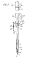
- Figure 2 shows an arrangement which can be operated in a vertical position. Those parts which are similar to corresponding parts of the first arrangement have the same reference numerals.
- a pointed needle 1 passes through a sheath 6 and into a tubular reservoir 2.
- the reservoir 2 terminates in a hopper 20 which has a feed tube 21 extending into the reservoir 2 to one side of the needle 1.
- the hopper 20 has a lug 22 projecting to one side of it.
- Pivoted on the lug 22 are two identical C-shaped levers 23.
- the levers 23 each have an arcuate slot 24 in them in which bear two pins 25 which are attached to a collar 26 which is free to slide up and down on the outside of the reservoir 2.
- the end of the needle 1 which is remote from the emitting tip 4 of the needle 1 is cranked and emerges through a slot 27 in the wall of the reservoir 2.
- the projecting end of the needle 1 is welded to the collar 26 so that movement of the collar 26 up and down the reservoir 2 causes a similar movement of the needle 1.
- a tension spring 28 is connected between the free ends of the levers 23 and a projection 29 on the wall of the reservoir 2. The spring 28 acts to urge the collar 26 towards the end of the reservoir 2 through which the emitting tip 4 of the needle 1 projects.
- the major part 30 of the needle 1 is of greater diameter than the sheath 6.
- a shoulder 31 is formed at the junction between the wider and narrower parts of the needle 1. The position of the shoulder 31 is such that when the collar 26 is in its rest position, the sheath 6 is closed off so that, initially, no liquid metal can pass to the emitting top 4 of the needle 1.
- a movable metal feed tube 32 carries at its free end a striker 33, which is arranged to enagage with the levers 23 when the feed tube 32 is inserted into the hopper 20.
- the feed tube 32 can be moved either by means of a solenoid 34, or a mechanical linkage.
- Leads 35 are provided to enable the hopper 20 and reservoir 2 to be heated so that the metal, ions of which are to be provided by the source, can be maintained in a liquid state or melted if it is provided in a powder form.
- the collar 26 and needle 1 remain in their lowest positions, so closing off the reservoir 2.
- the collar 26 is caused to move up the reservoir so retracting the needle 1 to a working position and opening the entrance to the sheath 6 so that liquid metal can pass freely to the emitting tip 4 of the needle 1, which projects from the sheath by the required amount.
- the striker 33 to move the levers 23 and the collar 26 further up the reservoir 2 so that the emitting tip 4 of the needle 1 is withdrawn into the sheath 6.
- the tube 32 is inserted a short way into the hopper 20, liquid metal, or powder is fed into the hopper 20 where it is melted, then the tube 20 is inserted further into the hopper 20 so that the needle 1 is withdrawn into the sheath 6 where its emitting tip is wetted, and the tube 32 is then withdrawn to a position where the emitting tip 4 of the needle 1 is in its working position in relation to the sheath 6.
- the feed tube 32 is withdrawn to a position where the striker 33 no longer is in contact with the levers 23 so that the ion source is electrically isolated and the necessary operating high voltage can be applied to it safely.
- the film strength of the liquid metal is sufficient to ensure that liquid metal continues to pass to the emitting tip 4 of the needle 1. If the metal film should break down in use, then the tube 32 can be moved back so as to retract the needle 1 fully again so that its emitting tip 4 can be re-wetted.
- both embodiments of the invention are used with one or more extractor electrodes. As these do not form part of the invention per se, they have not been illustrated.
- both the embodiments of the invention have been described as ion sources, whether they provide ions as a spray of charged droplets depends on the dimensions of the emitting tip 4 of the needle 1, the distance by which it projects from the sheath 6, and the clearance between the sheath 6 and the needle 1.
- the extraction potential also is a controlling factor.
- suitable dimensions are 100 ⁇ m for the diameter of the needle 1, a tip radius of about 5 pm, a clearance of about 25 ⁇ m between the sheath 6 and the needle 1, and a distance of about 0.1 cm between the end of the sheath 6 and the emitting tip 4 of the needle 1.
- charged droplets are provided when the needle 1 projects about 2 mm from the sheath 5 and has a tip radius of about 60 ⁇ m.
Landscapes
- Chemical & Material Sciences (AREA)
- Engineering & Computer Science (AREA)
- Combustion & Propulsion (AREA)
- Electron Sources, Ion Sources (AREA)
- Physical Or Chemical Processes And Apparatus (AREA)
Applications Claiming Priority (2)
| Application Number | Priority Date | Filing Date | Title |
|---|---|---|---|
| GB8205212 | 1982-02-22 | ||
| GB8205212 | 1982-02-22 |
Publications (2)
| Publication Number | Publication Date |
|---|---|
| EP0087896A1 true EP0087896A1 (de) | 1983-09-07 |
| EP0087896B1 EP0087896B1 (de) | 1986-10-01 |
Family
ID=10528525
Family Applications (1)
| Application Number | Title | Priority Date | Filing Date |
|---|---|---|---|
| EP83300846A Expired EP0087896B1 (de) | 1982-02-22 | 1983-02-18 | Flüssigmetallionenquelle |
Country Status (5)
| Country | Link |
|---|---|
| US (1) | US4577135A (de) |
| EP (1) | EP0087896B1 (de) |
| JP (1) | JPS58156344A (de) |
| DE (2) | DE87896T1 (de) |
| GB (1) | GB2115604B (de) |
Cited By (2)
| Publication number | Priority date | Publication date | Assignee | Title |
|---|---|---|---|---|
| EP0091777A3 (en) * | 1982-04-14 | 1985-05-22 | Hitachi, Ltd. | Liquid metal ion source |
| CN100458640C (zh) * | 2001-03-12 | 2009-02-04 | 皇家菲利浦电子有限公司 | 安全存储内容项目的接收设备和重放设备 |
Families Citing this family (6)
| Publication number | Priority date | Publication date | Assignee | Title |
|---|---|---|---|---|
| JPS60105148A (ja) * | 1983-11-11 | 1985-06-10 | Hitachi Ltd | 液体金属イオン源 |
| GB2190786A (en) * | 1986-05-21 | 1987-11-25 | Oxford Appl Res Ltd | Liquid metal field emission electron source |
| JPH0828199B2 (ja) * | 1987-03-25 | 1996-03-21 | 株式会社日立製作所 | 液体金属イオン源 |
| WO1992021138A1 (en) * | 1991-05-21 | 1992-11-26 | Analytica Of Brandford, Inc. | Method and apparatus for improving electrospray ionization of solute species |
| US7274383B1 (en) * | 2000-07-28 | 2007-09-25 | Clairvoyante, Inc | Arrangement of color pixels for full color imaging devices with simplified addressing |
| US6802456B2 (en) * | 2001-10-12 | 2004-10-12 | Microenergy Technologies, Inc | Electrostatic atomizer and method of producing atomized fluid sprays |
Citations (4)
| Publication number | Priority date | Publication date | Assignee | Title |
|---|---|---|---|---|
| US3475636A (en) * | 1967-11-14 | 1969-10-28 | Hughes Aircraft Co | Liquid-metal arc cathode with maximized electron/atom emission ratio |
| GB1442998A (en) * | 1973-01-24 | 1976-07-21 | Atomic Energy Authority Uk | Field emission ion sources |
| US4088919A (en) * | 1976-04-13 | 1978-05-09 | United Kingdom Atomic Energy Authority | Ion source including a pointed solid electrode and reservoir of liquid material |
| EP0037455A2 (de) * | 1980-02-08 | 1981-10-14 | Hitachi, Ltd. | Ionenquelle |
Family Cites Families (10)
| Publication number | Priority date | Publication date | Assignee | Title |
|---|---|---|---|---|
| US1979076A (en) * | 1933-06-17 | 1934-10-30 | Thomas J Neisworth | Liquid-dispensing apparatus |
| US2652175A (en) * | 1949-02-01 | 1953-09-15 | Nelson L Davis | Plug valve for controlling the flow of solids laden liquid |
| US2623766A (en) * | 1949-11-08 | 1952-12-30 | Richard Joseph Ulric | Sander for motor vehicles |
| US2720343A (en) * | 1950-07-07 | 1955-10-11 | James H Ross | Watchmakers' oiler |
| US2912143A (en) * | 1958-09-02 | 1959-11-10 | Louis W Woolfolk | Dispensing machine |
| US3331539A (en) * | 1966-09-08 | 1967-07-18 | Southwire Co | Metering device for controlling molten metal flow |
| DE2433781C2 (de) * | 1974-07-13 | 1984-12-13 | Kernforschungszentrum Karlsruhe Gmbh, 7500 Karlsruhe | Elektronenquelle |
| US4133918A (en) * | 1977-05-16 | 1979-01-09 | The Computervision Corporation | Method of marking semiconductors |
| JPS5633468A (en) * | 1979-08-23 | 1981-04-03 | Atomic Energy Authority Uk | Spray generating source of fine droplet and ion of liquid material |
| US4367429A (en) * | 1980-11-03 | 1983-01-04 | Hughes Aircraft Company | Alloys for liquid metal ion sources |
-
1983
- 1983-02-07 GB GB08303314A patent/GB2115604B/en not_active Expired
- 1983-02-07 US US06/464,677 patent/US4577135A/en not_active Expired - Fee Related
- 1983-02-18 DE DE198383300846T patent/DE87896T1/de active Pending
- 1983-02-18 DE DE8383300846T patent/DE3366511D1/de not_active Expired
- 1983-02-18 EP EP83300846A patent/EP0087896B1/de not_active Expired
- 1983-02-22 JP JP58028397A patent/JPS58156344A/ja active Pending
Patent Citations (4)
| Publication number | Priority date | Publication date | Assignee | Title |
|---|---|---|---|---|
| US3475636A (en) * | 1967-11-14 | 1969-10-28 | Hughes Aircraft Co | Liquid-metal arc cathode with maximized electron/atom emission ratio |
| GB1442998A (en) * | 1973-01-24 | 1976-07-21 | Atomic Energy Authority Uk | Field emission ion sources |
| US4088919A (en) * | 1976-04-13 | 1978-05-09 | United Kingdom Atomic Energy Authority | Ion source including a pointed solid electrode and reservoir of liquid material |
| EP0037455A2 (de) * | 1980-02-08 | 1981-10-14 | Hitachi, Ltd. | Ionenquelle |
Cited By (2)
| Publication number | Priority date | Publication date | Assignee | Title |
|---|---|---|---|---|
| EP0091777A3 (en) * | 1982-04-14 | 1985-05-22 | Hitachi, Ltd. | Liquid metal ion source |
| CN100458640C (zh) * | 2001-03-12 | 2009-02-04 | 皇家菲利浦电子有限公司 | 安全存储内容项目的接收设备和重放设备 |
Also Published As
| Publication number | Publication date |
|---|---|
| GB2115604B (en) | 1986-06-11 |
| GB8303314D0 (en) | 1983-03-09 |
| GB2115604A (en) | 1983-09-07 |
| DE3366511D1 (en) | 1986-11-06 |
| DE87896T1 (de) | 1984-01-05 |
| EP0087896B1 (de) | 1986-10-01 |
| US4577135A (en) | 1986-03-18 |
| JPS58156344A (ja) | 1983-09-17 |
Similar Documents
| Publication | Publication Date | Title |
|---|---|---|
| EP0087896B1 (de) | Flüssigmetallionenquelle | |
| CA1134132A (en) | Device for melting a solid body of adhesive material | |
| US7804073B2 (en) | Liquid metal ion gun | |
| JP3315720B2 (ja) | 液体金属イオン源及び加熱洗浄方法 | |
| US4631448A (en) | Ion source | |
| US3881087A (en) | Tip unit for an electric soldering gun | |
| US3377012A (en) | Apparatus for applying a coating of a fused material to an article | |
| US3443059A (en) | Hand tool for applying hot melt adhesives and the like | |
| US3312810A (en) | Automatic stud feeder | |
| EP0037455B1 (de) | Ionenquelle | |
| EP0080170A1 (de) | Feldemissionsionenquelle | |
| US4216894A (en) | Portable soldering apparatus | |
| EP0066474B1 (de) | Vorratsbehälter für eine Ionenquelle | |
| US3302274A (en) | Apparatus for making electrical connections | |
| GB1355715A (en) | Apparatus for dispensing attachment devices | |
| US2748245A (en) | Soldering tools | |
| JPS60115122A (ja) | 液体金属イオン源 | |
| US2848969A (en) | Solder feeder | |
| US3539160A (en) | Metal fusion control means | |
| US2824201A (en) | Soldering iron having a solder cartridge | |
| US3249991A (en) | Assembling apparatus | |
| JPH0578827A (ja) | 原料供給装置 | |
| JPH0643288A (ja) | 原子燃料のせん断装置 | |
| JPS6177240A (ja) | 軟x線発生装置 | |
| JPH03155025A (ja) | インジウムビスマスイオン源 |
Legal Events
| Date | Code | Title | Description |
|---|---|---|---|
| PUAI | Public reference made under article 153(3) epc to a published international application that has entered the european phase |
Free format text: ORIGINAL CODE: 0009012 |
|
| AK | Designated contracting states |
Designated state(s): DE FR NL |
|
| EL | Fr: translation of claims filed | ||
| TCNL | Nl: translation of patent claims filed | ||
| DET | De: translation of patent claims | ||
| 17P | Request for examination filed |
Effective date: 19840303 |
|
| GRAA | (expected) grant |
Free format text: ORIGINAL CODE: 0009210 |
|
| AK | Designated contracting states |
Kind code of ref document: B1 Designated state(s): DE FR NL |
|
| REF | Corresponds to: |
Ref document number: 3366511 Country of ref document: DE Date of ref document: 19861106 |
|
| ET | Fr: translation filed | ||
| PLBE | No opposition filed within time limit |
Free format text: ORIGINAL CODE: 0009261 |
|
| STAA | Information on the status of an ep patent application or granted ep patent |
Free format text: STATUS: NO OPPOSITION FILED WITHIN TIME LIMIT |
|
| 26N | No opposition filed | ||
| PGFP | Annual fee paid to national office [announced via postgrant information from national office to epo] |
Ref country code: FR Payment date: 19890118 Year of fee payment: 7 |
|
| PGFP | Annual fee paid to national office [announced via postgrant information from national office to epo] |
Ref country code: NL Payment date: 19890228 Year of fee payment: 7 |
|
| PGFP | Annual fee paid to national office [announced via postgrant information from national office to epo] |
Ref country code: DE Payment date: 19890822 Year of fee payment: 7 |
|
| PG25 | Lapsed in a contracting state [announced via postgrant information from national office to epo] |
Ref country code: NL Effective date: 19900901 |
|
| NLV4 | Nl: lapsed or anulled due to non-payment of the annual fee | ||
| PG25 | Lapsed in a contracting state [announced via postgrant information from national office to epo] |
Ref country code: FR Effective date: 19901031 |
|
| PG25 | Lapsed in a contracting state [announced via postgrant information from national office to epo] |
Ref country code: DE Effective date: 19901101 |
|
| REG | Reference to a national code |
Ref country code: FR Ref legal event code: ST |
|
| REG | Reference to a national code |
Ref country code: FR Ref legal event code: ST |