EP0087917B1 - Bohrapparat - Google Patents
Bohrapparat Download PDFInfo
- Publication number
- EP0087917B1 EP0087917B1 EP83300939A EP83300939A EP0087917B1 EP 0087917 B1 EP0087917 B1 EP 0087917B1 EP 83300939 A EP83300939 A EP 83300939A EP 83300939 A EP83300939 A EP 83300939A EP 0087917 B1 EP0087917 B1 EP 0087917B1
- Authority
- EP
- European Patent Office
- Prior art keywords
- tool
- mast
- drill pipe
- drive
- carriage
- Prior art date
- Legal status (The legal status is an assumption and is not a legal conclusion. Google has not performed a legal analysis and makes no representation as to the accuracy of the status listed.)
- Expired
Links
- 238000005553 drilling Methods 0.000 title claims description 34
- 230000007246 mechanism Effects 0.000 claims description 98
- 230000008878 coupling Effects 0.000 claims description 49
- 238000010168 coupling process Methods 0.000 claims description 49
- 238000005859 coupling reaction Methods 0.000 claims description 49
- 241000282472 Canis lupus familiaris Species 0.000 claims description 24
- 239000003638 chemical reducing agent Substances 0.000 claims description 7
- 230000002441 reversible effect Effects 0.000 claims description 6
- 230000015572 biosynthetic process Effects 0.000 claims description 5
- 238000006073 displacement reaction Methods 0.000 claims description 3
- 238000000926 separation method Methods 0.000 claims description 3
- 230000004323 axial length Effects 0.000 claims description 2
- 230000013011 mating Effects 0.000 claims 1
- 238000005520 cutting process Methods 0.000 description 6
- 238000000034 method Methods 0.000 description 5
- 230000004048 modification Effects 0.000 description 5
- 238000012986 modification Methods 0.000 description 5
- 239000012530 fluid Substances 0.000 description 4
- 238000005755 formation reaction Methods 0.000 description 4
- 229910000831 Steel Inorganic materials 0.000 description 3
- 230000000712 assembly Effects 0.000 description 3
- 238000000429 assembly Methods 0.000 description 3
- 230000006835 compression Effects 0.000 description 3
- 238000007906 compression Methods 0.000 description 3
- 230000002093 peripheral effect Effects 0.000 description 3
- 239000010959 steel Substances 0.000 description 3
- 229910052500 inorganic mineral Inorganic materials 0.000 description 2
- 239000000463 material Substances 0.000 description 2
- 239000011707 mineral Substances 0.000 description 2
- 230000009471 action Effects 0.000 description 1
- 230000005540 biological transmission Effects 0.000 description 1
- 230000008859 change Effects 0.000 description 1
- 238000010276 construction Methods 0.000 description 1
- 239000000356 contaminant Substances 0.000 description 1
- 229910003460 diamond Inorganic materials 0.000 description 1
- 239000010432 diamond Substances 0.000 description 1
- 230000009977 dual effect Effects 0.000 description 1
- 230000000694 effects Effects 0.000 description 1
- 230000003028 elevating effect Effects 0.000 description 1
- 230000005484 gravity Effects 0.000 description 1
- 238000011017 operating method Methods 0.000 description 1
- 230000000717 retained effect Effects 0.000 description 1
- 230000000630 rising effect Effects 0.000 description 1
- 125000006850 spacer group Chemical group 0.000 description 1
- 238000003466 welding Methods 0.000 description 1
Images






Classifications
-
- E—FIXED CONSTRUCTIONS
- E21—EARTH OR ROCK DRILLING; MINING
- E21B—EARTH OR ROCK DRILLING; OBTAINING OIL, GAS, WATER, SOLUBLE OR MELTABLE MATERIALS OR A SLURRY OF MINERALS FROM WELLS
- E21B15/00—Supports for the drilling machine, e.g. derricks or masts
-
- E—FIXED CONSTRUCTIONS
- E21—EARTH OR ROCK DRILLING; MINING
- E21B—EARTH OR ROCK DRILLING; OBTAINING OIL, GAS, WATER, SOLUBLE OR MELTABLE MATERIALS OR A SLURRY OF MINERALS FROM WELLS
- E21B17/00—Drilling rods or pipes; Flexible drill strings; Kellies; Drill collars; Sucker rods; Cables; Casings; Tubings
- E21B17/18—Pipes provided with plural fluid passages
-
- E—FIXED CONSTRUCTIONS
- E21—EARTH OR ROCK DRILLING; MINING
- E21B—EARTH OR ROCK DRILLING; OBTAINING OIL, GAS, WATER, SOLUBLE OR MELTABLE MATERIALS OR A SLURRY OF MINERALS FROM WELLS
- E21B19/00—Handling rods, casings, tubes or the like outside the borehole, e.g. in the derrick; Apparatus for feeding the rods or cables
- E21B19/08—Apparatus for feeding the rods or cables; Apparatus for increasing or decreasing the pressure on the drilling tool; Apparatus for counterbalancing the weight of the rods
- E21B19/084—Apparatus for feeding the rods or cables; Apparatus for increasing or decreasing the pressure on the drilling tool; Apparatus for counterbalancing the weight of the rods with flexible drawing means, e.g. cables
-
- E—FIXED CONSTRUCTIONS
- E21—EARTH OR ROCK DRILLING; MINING
- E21B—EARTH OR ROCK DRILLING; OBTAINING OIL, GAS, WATER, SOLUBLE OR MELTABLE MATERIALS OR A SLURRY OF MINERALS FROM WELLS
- E21B19/00—Handling rods, casings, tubes or the like outside the borehole, e.g. in the derrick; Apparatus for feeding the rods or cables
- E21B19/20—Combined feeding from rack and connecting, e.g. automatically
Definitions
- This invention relates to an apparatus for drilling in earth formations and, more particularly, to a drill rig for use in mineral exploration and the like of the type specified in the preamble of claim 1.
- drill rigs or apparatus have been especially designed for each different type of drilling and substantial changes of the drill rig were necessary in order to change from one type of drilling to another type of drilling. Further, many conventional drill rigs were specifically adapted for driving one size of drilling string. Again, substantial modifications of the apparatus are necessary to adapt the apparatus for a different size of drill string.
- DE-A-2 219 819 discloses a rotary drive mechanism for earth drilling apparatus comprising a housing, a drive member mounted in said housing for rotation therein about a rotary axis and having an axial throughbore opening at each end to the exterior of said housing, a drill pipe coupling tool telescopically mounted in said bore, first coupling means for non-rotatably coupling said tool to a drill pipe and a second coupling means for non-rotatably coupling said tool to said drive member, said coupling tool being telescopically movable between predetermined limits in said bore of said drive member driving operation of said mechanism.
- a still further drawback of conventional drill rigs is that they are not adapted for carrying out all of the functions which are necessary to drive and extract a drill string.
- the present invention provides an arrangement which is easily and quickly modified for assembling drill string and drilling a bore hole, dismantling a drill string and use with different sizes of drill pipe.
- a drill pipe drive mechanism adapted to rotatably drive any one of a plurality of removable generally tubular drill pipe coupling tools.
- the mechanism includes a housing and a coupling tool drive member or spindle rotatably and drivingly mounted in the housing.
- the spindle extends through the housing and is formed with an axial opening having means, such as splines or the like, for telescopingly receiving and non-rotatably coupling the drive spindles to any one of the coupling tools.
- the invention provides generally two categories of drill pipe coupling tools.
- the first category is intended primarily for use in assembling and driving a drill string into an earth formation while the second category is intended primarily for use in dismantling and extracting a drill string from an earth formation.
- Each tool of both categories differ from one another in that it is specifically constructed for coupling to a drill pipe of a particularly outside diameter.
- all of the tools have substantially the same exterior configuration so that all can be mounted in and driven by the drive spindle without any modification of the drive mechanism.
- Each coupling tool also includes an axial opening through which a portion of a drill pipe extends.
- One end, the upper end, of the tools is formed with an outwardly extending flange which is abuttingly engageable with the upper end of the drive spindle.
- the other end, the lower end is formed to receive means for removably retaining the tool operatively disposed in the drive spindle.
- the flange and retaining means cooperate to define predetermined limits of axial travel of the coupling tools with respect to the drive spindle during assembly and disassembly of drill pipe sections as will be described in greater detail later.
- a coupling tool of the appropriate size of the first category is selected and simply telescopingly inserted with the upper end of the drive spindle opening until the flange seats onto the upper end of the spindle and then the retaining means is attached to the lower end of the tool.
- the retaining means is simply removed from the tool mounted in the drive spindle, the tool telescopingly removed and the replacement or substitute tool inserted in the manner described above.
- the drilling rig is constructed in at least two modules so that each module can be independently transported to the drilling site.
- One module consists of an air compressor, including a compressed air reservoir and prime mover, for supplying air down the drill string as is well known.
- Another module consists of a mast assembly including a drill pipe drive mechanism and a hydraulic system, including prime mover, a hydraulic pump and controls, and fluid reservoir.
- the mast assembly is also constructed as an integral unit which is removably mounted on the module.
- the drive mechanism actuating means is arranged in such a manner as to reduce the strength requirements of the mast and thereby reduce the overall weight of the module.
- a drill pipe rotary drive mechanism for an earth drilling apparatus of the kind having a housing, a drive member mounted in said housing for rotation therein about a rotary axis and having an axial throughbore opening at each end to the exterior of said housing, a drill pipe coupling tool telescopically mounted in said bore, first coupling means for non-rotatably coupling said tool to a drill pipe and second coupling means for non-rotatably coupling said tool to said drive member, said coupling tool being telescopically movable between predetermined limits in said bore of said drive member during operation of said mechanism, is characterised by means on said tool cooperable with said drive member for limiting axial travel of said tool, said travel limiting means including shoulder means adjacent one end of said tool for abutting engagement with a first portion of said drive member for limiting travel of said tool in a first direction, and retaining means removably mounted on the other end of said tool, said retaining means being abuttingly engageable with a second portion of said drive
- said drive member and said coupling tool have a cylindrical body portion and a concentric, axial opening extending therethrough for receiving a portion of the length of a drill pipe therein.
- the primary function of the drill rig of the present invention is to assemble and rotatably drive a drill string into an earth formation at a desired drilling site and extract and dismantle the drill string.
- a drill string is comprised of serially connected lengths of drill pipe. Each length of pipe is threaded at each end for threaded engagement with one end of an adjacent pipe.
- one end of the pipe 10 is formed with internal thread and is referred to as a "box" 12.
- the other end of the pipe is formed with. an external thread, referred to as a "pin” 14.
- a cutting bit (not shown) is connected to the lowermost pipe section.
- Adjacent the box and pin of each pipe section are a pair of flattened diametrically opposed recesses or slots.
- the slots are provided for threadedly engaging and disengaging ("breaking") a pair of pipe sections.
- the slots adjacent the box are engageable with a hydraulic break-out wrench and called “box end break-out slots” 16, while the slots adjacent the pin, called “pin end break-out slots” 18, are engageable with pivoted dogs of a break-out tool removably mounted in the pipe drive mechanism.
- the present invention is particularly intended for use with double or dual-wall pipe sections wherein an inner pipe 20 is concentrically mounted within the above described pipe in a well known manner.
- the inner and outer pipe members together define an annular passageway 22 for communicating a fluid, such as air, from the surface to the cutting bit and the inner pipe defines a bore 24 for communicating the fluid and cuttings to the surface.
- Module 25 includes a sled or base 27 on which are mounted a mast assembly 30, a prime mover 28, such as a diesel engine, a hydraulic system 29 including a hydraulic pump and reservoir for supplying pressured fluid to various hydraulic cylinders and motors of a mast assembly 30.
- Module 26 includes a sled 31 carrying a compressed air system 33, including an engine 35, a compressor and reservoir 37, for supplying pressurized air via conduit 39 to an air swivel discharge device 41 mounted on a drill pipe drive mechanism of assembly 30. The discharge device, in turn, supplies air to passageway 22 as explained earlier.
- the air swivel discharge device also connects the outlet of bore 24 of inner pipe 20 to a cyclone 43 via conduit 45 in a manner well known to those skilled in this art. Lengths of pipe sections 10 are stored in a pipe rack 47 as shown in Figure 2.
- the mast assembly 30 ( Figure 2) includes a mast 32 having a track 34, a carriage 36 movable along the track, a drill pipe rotary drive mechanism 38 mounted on the carriage, a carriage actuating mechanism 40 mounted on the mast, a hoist mechanism 42 for hoisting the drill string or the drive mechanism mounted on the mast and a "break-out wrench" mechanism 44 ( Figure 25) mounted on the base of the mast.
- a mast 32 having a track 34, a carriage 36 movable along the track, a drill pipe rotary drive mechanism 38 mounted on the carriage, a carriage actuating mechanism 40 mounted on the mast, a hoist mechanism 42 for hoisting the drill string or the drive mechanism mounted on the mast and a "break-out wrench" mechanism 44 ( Figure 25) mounted on the base of the mast.
- the mast 32 operatively supports the other above-mentioned components of the assembly 30. It is operatively supported in a vertical position.
- the track 34 extends longitudinally of the mast and is comprised of a pair of facing channels disposed at two adjacent corners at the front side of the mast.
- the mast is illustrated in detail in Figures 2 and 18-23 (in phantom lines).
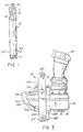
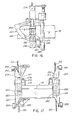
- the carriage 36 is connected to actuating mechanism 40 for vertical movement along track 34. Its primary function is to support the pipe drive mechanism 38. Carriage 36 is best illustrated in Figures 3, 4, 16 and 17.
- the rotary pipe drive mechanism 38 defines a rotary axis and is mounted on the carriage for movement therewith longitudinally of the mast and pivotal movement about .a horizontal axis between a first position and a second position.
- the first position is the normal operating position of the top drive wherein the rotary axis is substantially vertical and the top drive rotatably drives a pipe coupling tool for driving a drill string, threadedly engages or disengages a pair of pipe sections or hoists the drill string as will be explained in greater detail later.
- the second position is the position in which the top drive is disposed when pipe is added and removed.
- the top drive In this position, the top drive is disposed about 90° from the first position with the underside of the top drive facing outwardly away from the mast and the rotary axis is substantially horizontal.
- a detent mechanism is provided for resiliently retaining the top drive in either position.
- the top drive is illustrated in Figures 3-6.
- the carriage actuating mechanism 40 is generally comprised of a pair of hydraulic cylinders disposed on opposite sides of the mast, adjacent the side on which the carriage is movable, and mounted on the base of the mast.
- the hydraulic cylinders are operatively connected to the carriage by cables arranged for selectively, reversibly actuating the carriage.
- the actuating mechanism is best illustrated in Figures 18-21.
- the hoist mechanism 42 is generally comprised of a single hydraulic cylinder disposed adjacent the side of the mast opposite the side on which the carriage is mounted and is mounted on the crown of the mast.
- the hoist mechanism is selectively connectable to either the upper length of pipe of drill string or the top drive for raising the drill string, as will be explained in greater detail hereinafter.
- the hoist mechanism is best illustrated in Figures 22 and 23.
- the break-out wrench mechanism 44 is a hydraulically actuated, extendable and retractable wrench for selectively engaging a pipe section and preventing rotation thereof during assembly and disassembly of a drill string.
- the break-out mechanism is best illustrated in Figure 25.
- the top drive 38 is generally comprised of a transmission or gear box 50, a speed reducer 52, and a hydraulic motor 54.
- the speed reducer 52 is drivingly connected to the input shaft 56 of the gear box and bolted to the gear box casing 58 while the hydraulic motor 54, which is preferably of the reversible, variable displacement type, is drivingly connected and bolted to the speed reducer 52, as shown in Figures 3 and 4.
- the motor is connected to hydraulic system 29 via appropriate conduits 53 ( Figure 4).
- the speed reducer and motor are of conventional construction and accordingly are neither illustrated nor described in detail herein.
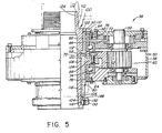
- Casing 58 is generally of box-shaped configuration and houses a drive pinion 60, which in the illustrated embodiment is integral with input shaft 56, a crown gear 62 which meshingly engages with pinion 60 and a tubular drive spindle 64 bolted to crown gear 62.
- the drive spindle is adapted to removably receive and drive any one of the several pipe engaging or coupling devices so that the top drive can be quickly and readily modified to drive pipe of different sizes and carry out functions other than driving the drill string including threadedly engaging and disengaging adjacent pipe sections and hoisting the drill string.
- Drive spindle 64 is formed with a radially outwardly extending flange 66 adjacent its midportion, which flange is abuttingly engaged with and secured by bolts 68 to a radially inwardly extending flange 70 of crown gear 62, as best shown in Figure 5.
- the drive spindle 64 and crown gear 62 are rotatably mounted in the casing 58 by upper and lower ball bearing assemblies 72 and 74.
- Upper and lower oil seals 76 and 78 are disposed between each end of the drive spindle 64 and bore 80 of the casing 58 as shown in Figure 5. The oil seals are protected and retained in position by upper and lower oil seal guard rings 82 and 84 bolted to casing 58.
- Drive spindle 64 is also formed with a bore 86 which telescopingly and removably receives the pipe coupling devices.
- Bore 86 is formed with at least one, but preferably a plurality of longitudinally extending keyways 88.
- upper annular edge 90 of spindle 64 serves to support the removable pipe coupling tools.
- actuation of motor 54 effects rotation of shaft 56 and pinion 60. in one direction and rotation of crown gear 62 and spindle 64 in the opposite direction.
- Reverse rotation of the motor results in reverse of the motor results in reverse rotation of the spindle and, inasmuch as the motor is of the variable displacement type, the spindle can be driven at various speeds and used for various purposes such as rotatably driving a drill string and making and breaking tool joints between adjacent pipe sections.
- FIGS 5 and 7-11 illustrate pipe coupling devices or tools which form an important part of the present invention.
- the tool generally designated by reference numeral 100 in Figures 5 and 11 is used primarily for rotatably driving a drill string and threadedly engaging adjacent, axially aligned pipe sections.
- the tool generally designated by reference numeral 170 in Figures 7-10 is intended for use primarily as a break-out tool, i.e., for threadedly disengaging adjacent pipe sections. However, both tools can also be used for hoisting the drill string.
- Drive tool 100 is generally comprised of a cylindrical body portion 102 having an internal thread 104 at its lower end 106, at least one, but preferably a plurality of longitudinal, equally spaced keys 108, and a radially outwardly extending flange 110 at its upper end 112.
- An externally threaded neck portion 114 extends axially from the upper end of tool 100.
- An external radially outwardly facing circumferential slot 116 is formed adjacent the lower end 106 of the tool.
- Thread 104 is formed to threadedly receive one end of a cylindrical tool known as a "saver sub".
- a saver sub is generally a short length of pipe externally threaded at both ends and is normally used at locations where extensive threading and unthreading occurs. Thus, the relatively inexpensive save sub takes most of the wear.
- the other end of the save sub is threadedly received in the box end of a length of drill pipe. It will be understood that the lower end of the tool 100 could be formed with an external thread adapted to be connected directly to the box end of a drill pipe thereby obviating the need of a saver sub if so desired.
- the keys 108 are formed by welding elongated steel bars 118 in four elongated, longitudinal slots 120 formed on the outer cylindrical periphery of the tool 100.
- the keys are received in keyways 88 of drive spindle 64 and serve to transmit torque from the drive spindle 64 to the body portion of the tool.
- axial splines used hereinafter is intended to refer to any arrangement which non-rotatably couples two components while permitting relative axial movement therebetween.
- Flange 110 defines a radial annular shoulder 122 which abuttingly engages upper annular edge 90 of spindle 64.
- the flange serves as a "flinger" - a means whereby contaminants, such as dirt, are centrifugally propelled away from the upper oil seals 76.
- Threaded neck portion 114 is adapted to be threadedly connected to an air discharge swivel 41, as illustrated in phantom in Figure 5a.
- the neck 114 defines an opening 124 to receive an inner pipe section, as also shown in Figure 5a, which is sealingly connected to the air discharge swivel and provides an annular passageway between the inner pipe and opening 124 for communicating air to passageway 22.
- an air discharge swivel is a device for connecting a supply of air to annular passageway 22 and bore 24 of the inner pipe to an exhaust conduit which, in turn, is connected to a cyclone 43 for separating air from cuttings while the drill string rotates. Air swivel discharge devices are well known and therefore are not described in detail herein.
- a pipe coupling tool 100 remains connected to the air discharge swivel unless a tool for use with a different sized pipe is required. In such case, the tool is simply threadedly removed and the desired tool is threaded onto the air discharge swivel.
- a split thrust ring 130 and a retaining ring 132 are provided for preventing inadvertent removal of the drive tool 100 and for limiting longitudinal or axial travel of the tool 100 relative to the top drive. As will be described in greater detail later, such movement is desirable when threadedly engaging adjacent lengths of pipe.
- split ring 130 is comprised of a pair of arcuate arms 134,134 connected at one end for pivotal movement about a pin 136.
- arms 134, 134 define a cylindrical surface 138 whose diameter is slightly larger than the inner diameter of peripheral slot or groove 116 of tool 100.
- ring 130 is adapted to be fitted into the slot 116 and is readily removable therefrom by pivotally manipulating arms 134, 134.
- Ring 132 is provided to prevent separation of arms 134,134 of the split ring yet permit quick removal of the split ring from the tool and the tool from the top drive.
- Ring 132 is formed with a skirt portion 140 and an annular shoulder portion 142.
- Shoulder portion 142 defines axial opening 144 which telescopingly receives body portion 102 of tool 100. Opening 144 is formed with four keyways 146 for slidingly receiving keys 108 of the tool.
- the skirt portion 140 is formed with an opening 147 sized to loosely receive the outer periphery of split ring 130 as shown in Figure 5.
- the retainer ring 132 is maintained in the position shown in Figure 5 by gravity.
- retaining ring 132 is telescopingly moved upwardly, as viewed in Figure 5, the split ring 130 is removed from slot 116 by opening or separating arms 134, 134 and ring 132 is slid downwardly and away from the tool.
- the tool (and its associated air discharge swivel) is then free to be removed from the top drive by moving it axially upwardly and outwardly of the drive spindle.
- the reverse procedure is adopted to operatively locate a tool in the top drive.
- the distance between the shoulder 122 of the drive tool 100 and the upper surface 148 of ring 132 is arranged to be longer than the axial length of the drive spindle 64 by an amount at least equal to the length of the thread of the box (or pin) of a drill pipe. This avoids the need of incrementally lowering the top drive when the top drive is used to thread an additional pipe section to the drill string in a manner to be described later.
- Coupling tool 150 ill_ustrated in Figure 11 is in all material respects the same as that illustrated in Figure 5 except that it is constructed for use with drill pipe of smaller outside diameter.
- the body portion 152, keys 154, annular flange 156, neck portion 158 and peripheral slot 160 are identical to those of tool 100 so that tool 150 cooperates with drive spindle 64 and split and retaining rings 130 and 132 in precisely the same manner as tool 100.
- an insert 162 replaces internal thread 104 of tool 100 and provides an internal thread 164 of smaller diameter than thread 104 for use with smaller drill pipe. As shown, insert 162 is welded to the body portion.
- the above described coupling tools can be used to transmit axial forces to the drill string in situations where hoisting effort is required.
- the carriage actuating mechanism is actuated so as to apply a vertical force to the carriage which force is transmitted to the top drive casing.
- the force is in turn transmitted to the drive spindle, via the ball bearing assemblies and then to the drive tool flange, body portion and drill pipe.
- Figures 7 and 8 illustrate a "break-out" tool 170 intended for use in threadedly disengaging two pipe sections and, hoisting the drill string in the event that additional hoisting effort is required to release a jammed drill string.
- Break-out tool 170 is constructed so as to be received in and rotatably driven by drive spindle 64 in the same manner as drive tool 100.
- tool 170 is formed with a tubular body portion 172 having four equally spaced keys 174 and a peripheral slot 176 adjacent lower end 178 thereof for reception of split ring 130 and retaining ring 132.
- the upper end 180 is formed with a flange 182 having an annular shoulder 184 for abutting engagement with upper edge 90 of drive spindle 64 and application of an upward thrust to the tool when required.
- the length of tool 170 is such as to permit axial travel of the tool relative to drive spindle 64 and thereby avoid the need of incrementally raising the top drive as a pipe section is unthreaded.
- tool 170 is mounted on and removed from the drive spindle 64 in precisely the same manner as tools 100 and 150.
- the body portion is formed with an axial bore or opening 186 adapted to telescopingly receive a . length of pipe section as shown in dotted lines in Figure 8.
- each dog 190 is formed with a cylindrical portion 192 from the opposite ends of which extend stub shafts or pins 194 received for pivotal movement in blind bores 196 formed in abutting surfaces 198 and 200 of discs 187 and 188 respectively. Also formed in discs 187 and 188 adjacent each bore 196 are chambers 202 which receive torsion or spiral springs 204 which serve to bias dogs 190 toward the solid line position shown in Figure 8.
- each dog 190 Extending radially outwardly and longitudinally of each dog 190 is a jaw portion 206 adapted to be received in previously mentioned pin end break-out slots 18 of a pipe section as shown in Figure 8.
- the break-out tool 208 illustrated in Figures 9 and 10 is in all material respects the same as the tool illustrated in Figures 7 and 8 except that it is used with a pipe section of smaller outside diameter.
- This tool utilizes the same tubular body portion 172 but discs 210 and 212 having a smaller inside diameter and locating the dogs 214 closer together are utilized.
- an inner cylindrical tube 216 is concentrically disposed within the tubular body position. As shown, the upper end of the inner tube is welded to the lower disc 212 while a spacer block 213 is disposed between the lower end of the inner tube 216 and the body portion 172.
- the drive tool 100 and air discharge swivel 43 are removed from the top drive in the manner previously explained and the break-outtool 170 is operatively positioned on the top drive as also previously explained with respect to drive tool 100.
- the carriage actuating mechanism is then actuated to lower the carriage, and hence the top drive, to a position adjacent the bottom of the mast. It will be understood that the top drive will remain in this position during the break-out operation unless the hoist mechanism is incapable of raising the drill string in which case the carriage actuating mechanism is used to provide additional vertical thrust.
- break-out wrench has been engaged with the box end break-out slots 16 of the uppermost pipe section of the drill string and supports the drill string, at least in part. So arranged, the rig is ready for the break-out operation.
- a hoist plug secured to the free end of a cable connected to the hoist mechanism to be described in greater detail later, is passed thrugh the break-out tool bore 186 and threaded into the box end of the uppermost pipe section of the drill string.
- the hoist mechanism is then actuated slightly so as to remove the weight of drill string from the break-out wrench and the wrench is retracted.
- the hoist mechanism is thereafter actuated to raise the drill string the length of a pipe section. As the drill string is raised, the periphery. of the drill pipe surface pivots the dogs 190 to the dotted line position shown in Figure 8 against the bias of torsion springs 204.
- top drive is then reversely rotated thereby reversing rotating the uppermost pipe section, via drive spindle 64 and break-out tool 190.
- upper pipe section As the upper pipe section is rotated, its pin unthreads from the box of the next lower pipe section and the pipe moves upwardly under the influence of the threads as well as that of a spring mechanism associated with the hoist mechanism. Further, dogs 190 move relatively downwardly in the pin end break-out slots 18 and thus slots 18 must be of sufficient length to accommodate such movement.
- the hoist mechanism is actuated to raise the separated pipe section free of the top drive.
- the hoist is then actuated to lower the pipe section which is placed in a pipe rack 47 ( Figure 2) disposed adjacent the drill rig.
- the hoist plug is removed from the pipe section and the operation is repeated until the drill string is completely dismantled.
- the mast 32 is an elongated parallel-piped structure defined by two rear tubular steel corner posts 230, two front posts 232 constructed of channel members, whose open sides face one another and define track 34, and intermediate tubular steel braces 234.
- the mast is also formed with a base 236 and a crown 238.
- the mast is disposed in an upright position during use.
- the mast is adapted to be pivoted to a horizontal position during transport on sled or skid 27. This is achieved by a pair of outwardly projecting pins 242 welded or otherwise secured to a brace member 234, as shown.
- the pins 242 are received in cradles 244 of support posts 246 associated with sled 27.
- a support bracket 248 supports the upper end of the mast during transport and a wedge lock at the base of the mast will maintain the mast in its upright position during use.
- the carriage 36 is comprised of two sections 250 and 252 which are mirror images of one another. Section 250 is associated with and supports the left side of the top drive and while section 252 is associated with and supports the right side of the top drive. While the following description is referrable to section 250, it is to be understood that the description is equally applicable to section 252.
- carriage section 250 includes an elongated outer plate 254 having rollers 256 and 258 rotatably mounted at its opposite ends. Rollers 256 and 258 are disposed for movement within the channel shaped members defining track 34. Spaced laterally inwardly of plate 254 is an inner plate 260 connected to plate 254 by laterally extending, spaced connector plates 262, 262. Inner plate 260 is formed with an arcuate, rearwardly extending detent plate 264 having an arcuate guide surface 266 and recesses 268 and 270 spaced approximately 90° apart.
- a pivot pin 272 having an inwardly disposed head 274.
- the opposite end of pin 272 is welded or otherwise secured to plates 254 and 260.
- Pin 272 extends inwardly beyond inner plate 260 and defines between plate 260 and head 274 a journal portion received in a two part support and pivot block 276 bolted to the casing of the top drive.
- the top drive is supported for pivotal movement about the axis of pins 272 between a first and a second position.
- the rotary axis of drive spindle is vertically disposed and the top drive may be used for the previously described operations.
- the second position of the top drive facilitates the addition of lengths of pipe to the top drive.
- the top drive is disposed about 90° about the axis of pins 272 from the first position with the underside of top drive facing away from the mast.
- a length of pipe section may be threaded onto the saver sub attached to the drive tool by either manually rotating the pipe or slowly rotating the top drive.
- detent roller assembly 280 Secured to the underside of the top drive casing is a detent roller assembly 280 which houses a spring biased roller 282 (Figure 16). Roller 282 engages guide surface 266 of detent portion 264 of plate 260. Recesses 268 and 270 define the first and second positions respectively of the top drive. The load of the spring within detent roller assembly 280 may be adjusted by nut 284.
- an air swivel torque slide 288 Secured to one of the pivot blocks 276 is an air swivel torque slide 288 for preventing rotation of the outer housing of the air discharge swivel.
- the carriage actuating mechanism 40 is comprised of a "pull-up” assembly 300 ( Figures 18 and 19) and a “pull-down” assembly 302 ( Figures .20 and 21). Both assemblies are actuated by the same two hydraulic cylinders 304, 304 vertically disposed on laterally opposed sides of the mast 32. The two cylinders are secured to the base of the mast by a support bracket 306 (see Figures 18 and 20). Attached to the free end of the piston rod of each cylinder is a pulley assembly 307 having pulleys 308 and 310.
- the pull-up assembly includes a cable 312 having one end 314 secured to one section of the carriage in the manner shown in Figures 16 and 17.
- Cable 312 is trained about pulley 308 of one pulley assembly 307, pulleys 316 and 318 ( Figure 19) rotatably mounted in the mast base, and pulley 308 of the other pulley assembly 307.
- the other end 319 of cable 312 is then releasably connected to the other section of the carriage as also shown in Figures 16 and 17.
- a turnbuckle 322 is provided for adjustably tensioning the cable.
- the pull-down assembly 302 is comprised of two cables 330 and 332 each associated in an identical manner with one of the hydraulic cylinders 304.
- One end 334 of each cable is adjustably and removably connected to the crown of the mast, as best shown in Figure 20, while the other end 336 of each cable is removably secured to a respective section of the carriage, as shown in Figures 16 and 17.
- each cable extends downwardly and trained about upper pulley 310 of pulley assembly 307, upwardly and trained about pulley 338 rotatably mounted on the crown, and downwardly and trained about pulley 340 rotatably mounted in the mast base.
- ends 336 of the cables 330 and 332 move downwardly and apply a downward thrust or force to the carriage and, hence, the top drive.
- the hoise or haul-out mechanism 42 is illustrated in Figures 22 and 23 and is comprised of a single inverted, vertically extending hydraulic cylinder 350 mounted on the mast crown adjacent the rear side 352 (remote from the top drive) of the mast.
- a pulley 354 is secured to the end of the piston rod 356 of the cylinder.
- a pivot head assembly 358 pivotally mounted atop the mast crown, as shown in Figure 23, is comprised of a pair of spaced arms 360 connected at one end 362 to the crown and centrally supported by a compression spring assembly 364.
- a stop 363 is provided to limit downward travel of the assembly.
- a pair of pulleys 366 and 368 are rotatably mounted on arms 360 as shown.
- a cable 370 has one end 372 connected to the crown and its intermediate portion trained about pulleys 354, 366 and 368.
- the other end 374 of the cable 370 is fitted with a hook (not shown) or the like for connection to a hoist plug 376 or a bail (not shown) secured to the upper end of the air discharge swivel.
- the pivot head assembly 358 is provided to maintain cable 370 in tension during the break-out operation as well as maintain an upward force on the pipe section being removed without incrementally raising the hoist mechanism.
- Hoist plug 376 is illustrated in Figures 24a and 24b and is comprised of a tubular body portion 377 having an externally threaded lower end portion 378 which is threadedly engageable with the box end of a drill pipe section.
- a shaft 379 having a head 380 at its lower end and a thread 381 at its upper end is disposed in body portion 377.
- Head 380 bears against a thrust bearing 382 which in turn bears against an internal shoulder 383 in the plug body.
- An oil seal 384 and retaining ring 385 close the lower end 378 of the plug.
- a clevis 386 is threaded onto upper end 381 of shaft 379 against a ball bearing 387.
- a removable clevis pin 388 is mounted in the clevis as shown for securing the end 374 of cable 370 to the hoist plug.
- the body portion is formed with a spoked, ringed handle 389 at its upper end for manually rotating the body portion with respect to the shaft.
- threaded portion 378 is formed with a pair of opposed flattened surfaces 390 so that the lower end of the plug can be passed between the dogs 190 of a break-out tool 170 without moving the dogs.
- end 374 of cable 370 is secured to clevis 386 and the lower end 378 of the plug is passed through bore 186 oftool170 and threadedly engaged with the box of the uppermost drill pipe section of the drill string to be raised by rotating handle 389 and hence plug body 377.
- Cylinder 350 is then actuated to extend piston rod 356, and raise end 374 of cable 370, the hoist plug 376 and drill string.
- piston rod 356 is retracted to lower the drill pipe section, the drill pipe section is unthreaded from the hoist plug section and placed in the pipe rack.
- the break-out wrench assembly is illustrated in Figure 25 which is a top view of the mast base.
- the assembly includes a wrench member 400 having a wrench head 402 and an elongated body portion 404.
- Wrench member is slidably mounted on the upper surface 406 of the mast base for reciprocation from a first extended position illustrated in Figure 25 whereat the wrench is in engagement with a section of pipe and a second, retracted position whereat the wrench is clear of the drill string permitting rotation and/or axial movement of the latter.
- Wrench head 402 is formed with a pair of opposed flattened surfaces 408 slidingly engageable with the box end break-out slots 16 of a pipe section.
- the wrench member is guided for reciprocal movement by a bracket 410 bolted to surface 406 and associated with body portion 404 and a pair of guides 412 secured to surface 406 and associated wing projections 414 extending from head 402.
- a bar 416 secured to body portion 404 extends through a slot 418 in surface 406 into the mast base and is connected to a hydraulic cylinder 420 disposed within the base.
- the wrench head is supported by a surface 422 of a pipe guide member 424 formed in the mast base.
- the carriage actuating mechanism 40 is actuated to move the top drive mechanism 38 to a convenient lower position on the mast.
- An air discharge swivel mechanism having an appropriate pipe coupling tool 100 or 150 attached thereto is inserted into the bore 86 in spindle 64.
- the split thrust ring 130 and retaining ring 132 are then assembled on the pipe coupling tool.
- the top drive 38 is manually pivoted about pins 272 from its first position to its second position.
- the top drive is maintained in the second position by the detent assembly. It should be noted at this point that the pins 272 extend through or near the centroid of the top drive, speed reducer, motor and air discharge swivel so that relatively little effort is required to move the top drive between its two positions.
- An appropriate cutting bit is connected to the down hole end of the first drill pipe and the box end of such pipe is threaded onto the saver sub extending from the drive tool either by manually rotating the drill pipe or rotating the top drive while the pipe section is held stationary.
- the carriage actuating mechanism is actuated to raise the top drive to the upper end of the mast 32.
- the weight of the pipe overcomes the effort of the spring detent assembly and the pipe moves towards a vertical position.
- the stop 286 engages the detent housing and thereby positively locates the top drive in its first, driving position.
- the lower end of the pipe is placed above the pipe guide in the mast base and the carriage actuating mechanism is actuated to lower the top drive until the cutting bit engages the ground.
- the carriage actuating mechanism is deactivated and the rig is ready for drilling.
- Motor 54 is actuated to begin the drilling operation. The drilling continues until the box end break-out slots 16 are vertically aligned with the break-out wrench. Hydraulic cylinder 406 is actuated to extend break-out wrench 400. The top drive is rotated if necessary in order to angularly align the box and break-out slots with the flattened surfaces 408 of wrench 400. Thus, the portion of the drill string in the bore hole is held against rotation. Motor 54 of the top drive is reversed so as to threadedly disengage the saver sub from the box of the drill pipe. Thereafter, the carriage actuating mechanism is activated to raise the top drive slightly. The top drive is then pivoted to its second position and is ready to repeat the foregoing procedure.
- the mode of adding the second and subsequent pipe sections to the drill string is substantially the same as the mode of adding the first pipe.
- a new length of pipe is threaded onto the saver sub as explained previously.
- the top drive is raised until the pin of the new pipe clears the box of the pipe already in place.
- the top drive is then lowered while the pin of the new pipe enters the box of the pipe already in place and the lower edge of the drive spindle abuttingly engages the upper surface 148 of retaining ring 132.
- the top drive is then rotated until the new pipe is fully threadedly engaged with the pipe already in place. It will be noted that as the new pipe is being threaded, it moves downwardly with respect to the top drive by virtue of the longitudinal clearance originally provided between the drive tool and the drive spindle so that it is not necessary to incrementally lower the top drive as the new pipe section is being threaded.
- the carriage actuating mechanism is actuated to apply an upward thrust to the drill strip via the top drive and coupling tool.
- the hoist mechanism is attached to a bail (not shown) on the air discharge swivel or the top drive and it is actuated to apply an additional upward thrust to the drill string. Once the drill string is cleared, the hoist mechanism is disconnected and the top drive motor is activated to ream the bore hole and continue drilling.
- the break-out wrench When it is desired to remove the drill string from the bore hole, the break-out wrench is engaged with the box end break-out slots 16 of the uppermost pipe section of the drill string and the top drive is reversibly rotated so as to disengage the saver sub from the box end of the uppermost pipe of the drill string.
- the top drive is then raised to a convenient position whereat the air discharge swivel and its accompanying pipe coupling tool 100 (or 150) are removed by removing split thrust ring 130 and retaining ring 132 as previously explained.
- a break-out tool 170 is inserted into the drive spindle 64 and the split thrust ring and retainer ring are assembled thereon so as to retain the break-out tool operatively disposed on the top drive.
- the top drive is then lowered to a position adjacent the lower end of the mast.
- a hoist plug 380 is then secured to the end 374 of cable 370 of the hoist mechanism, extended through the opening in the break-out tool 170 and threadedly engaged with the threads in the box end of the uppermost pipe of the drill string.
- the hoist mechanism is actuated to raise the drill string slightly so as to move the weight of the drill string from the break-out wrench.
- the break-out wrench is retracted and the hoist mechanism is actuated to raise the drill string the length of a drill pipe. As this occurs, the drill string passes through axial bore 186 of the break-out tool and the dogs 190 are pivoted outwardly of bore 186 against the bias of spring 204.
- the compression spring assembly 364 of pivot head assembly 358 of the hoist mechanism are compressed and upwardly bias the drill string.
- the upper drill pipe is unthreaded from the drill string and moves upwardly both under the influence of the action of unthreading and the bias of the compression spring assembly.
- dogs 190 move relatively downwardly of the pin end break-out slots and the break-out tool moves axially upwardly relative to the top drive. As previously explained, incremental vertical adjustment of the top drive is not necessary.
- the hoist mechanism is retracted and the decoupled pipe is placed in the pipe rack. The above described procedure is then repeated until the drill string is fully dismantled.
Landscapes
- Engineering & Computer Science (AREA)
- Life Sciences & Earth Sciences (AREA)
- Geology (AREA)
- Mining & Mineral Resources (AREA)
- Mechanical Engineering (AREA)
- Physics & Mathematics (AREA)
- Environmental & Geological Engineering (AREA)
- Fluid Mechanics (AREA)
- General Life Sciences & Earth Sciences (AREA)
- Geochemistry & Mineralogy (AREA)
- Earth Drilling (AREA)
Claims (14)
Priority Applications (2)
| Application Number | Priority Date | Filing Date | Title |
|---|---|---|---|
| AT83300939T ATE27332T1 (de) | 1982-02-24 | 1983-02-23 | Bohrapparat. |
| AT85106086T ATE49453T1 (de) | 1982-02-24 | 1983-02-23 | Bohrrohr. |
Applications Claiming Priority (4)
| Application Number | Priority Date | Filing Date | Title |
|---|---|---|---|
| CA000396949A CA1159442A (en) | 1982-02-24 | 1982-02-24 | Dual-wall drill pipe |
| CA396949 | 1982-02-24 | ||
| CA396947 | 1982-02-24 | ||
| CA000396947A CA1204428A (en) | 1982-02-24 | 1982-02-24 | Earth drilling apparatus |
Related Child Applications (1)
| Application Number | Title | Priority Date | Filing Date |
|---|---|---|---|
| EP85106086.3 Division-Into | 1985-05-17 |
Publications (2)
| Publication Number | Publication Date |
|---|---|
| EP0087917A1 EP0087917A1 (de) | 1983-09-07 |
| EP0087917B1 true EP0087917B1 (de) | 1987-05-20 |
Family
ID=25669594
Family Applications (2)
| Application Number | Title | Priority Date | Filing Date |
|---|---|---|---|
| EP83300939A Expired EP0087917B1 (de) | 1982-02-24 | 1983-02-23 | Bohrapparat |
| EP19850106086 Expired EP0165479B1 (de) | 1982-02-24 | 1983-02-23 | Bohrrohr |
Family Applications After (1)
| Application Number | Title | Priority Date | Filing Date |
|---|---|---|---|
| EP19850106086 Expired EP0165479B1 (de) | 1982-02-24 | 1983-02-23 | Bohrrohr |
Country Status (3)
| Country | Link |
|---|---|
| EP (2) | EP0087917B1 (de) |
| AU (3) | AU562909B2 (de) |
| DE (2) | DE3381091D1 (de) |
Cited By (2)
| Publication number | Priority date | Publication date | Assignee | Title |
|---|---|---|---|---|
| CN112761535A (zh) * | 2021-02-03 | 2021-05-07 | 上海中联重科桩工机械有限公司 | 旋挖钻机钻杆、旋挖钻机及旋挖钻机钻杆变节数方法 |
| CN117514040A (zh) * | 2024-01-08 | 2024-02-06 | 中勘城地岩土科技(苏州)有限公司 | 一种旋转桩钻机 |
Families Citing this family (27)
| Publication number | Priority date | Publication date | Assignee | Title |
|---|---|---|---|---|
| US4753300A (en) * | 1984-10-03 | 1988-06-28 | Triten Corporation | Hydraulic top drive for wells |
| DE3503171A1 (de) * | 1985-01-31 | 1986-08-07 | Fried. Krupp Gmbh, 4300 Essen | Vorrichtung zum schlagenden bohren von langen loechern |
| FI885483A7 (fi) * | 1987-11-26 | 1989-05-27 | Robbins Co | Kraftoeverfoeringshuvud foer en bergborrmaskin. |
| GB0011789D0 (en) * | 2000-05-16 | 2000-07-05 | Vick Steve Int Ltd | Breakout assembly for driling rods |
| CN101798907B (zh) * | 2010-03-31 | 2012-10-17 | 北京市三一重机有限公司 | 回转圈 |
| CN101799106B (zh) * | 2010-03-31 | 2012-05-30 | 北京市三一重机有限公司 | 细长杆件的支撑装置 |
| CN101813572B (zh) * | 2010-03-31 | 2012-11-28 | 北京市三一重机有限公司 | 用于细长杆的试验检测装置 |
| CN101832873B (zh) * | 2010-03-31 | 2012-12-19 | 北京市三一重机有限公司 | 用于细长杆件的试验检测装置 |
| CN108086922A (zh) * | 2017-12-30 | 2018-05-29 | 贵州高峰石油机械股份有限公司 | 一种提高螺杆钻具使用性能的方法及超级螺杆钻具 |
| CN108952577A (zh) * | 2018-06-15 | 2018-12-07 | 焦作市恒利水文地质工程有限责任公司 | 一种钻具定位定向装置 |
| CN109025836B (zh) * | 2018-07-29 | 2023-08-25 | 徐州景安重工机械制造有限公司 | 一种全回转套管钻机驱动装置顶层支架 |
| CN113006789B (zh) * | 2019-12-19 | 2024-05-07 | 宝钢集团新疆八一钢铁有限公司 | 一种zdy3200l型煤矿用全液压履带式坑道钻机推拉缸改进方法 |
| CN112878924B (zh) * | 2021-01-27 | 2024-04-02 | 南通洪源地质工程材料有限公司 | 一种大直径无缝钻管及其加工工艺 |
| CN113153139A (zh) * | 2021-05-24 | 2021-07-23 | 陈志红 | 一种微型山地钻机 |
| CN115478774B (zh) * | 2021-06-16 | 2025-03-18 | 浙江华东建设工程有限公司 | 一种便于快速固定的小型勘探钻孔设备 |
| CN113982485B (zh) * | 2021-10-23 | 2023-12-15 | 浙江必利夫检测科技有限公司 | 一种矿山行业手传振动危害的缓解支撑仪 |
| CN114109267B (zh) * | 2021-11-12 | 2023-04-18 | 贵州建工集团第一建筑工程有限责任公司 | 一种锚索成孔施工垫具及锚索成孔施工方法 |
| CN114412377A (zh) * | 2022-01-25 | 2022-04-29 | 陕西太合智能钻探有限公司 | 矿用钻杆 |
| CN117188983A (zh) * | 2022-05-30 | 2023-12-08 | 中国石油天然气集团有限公司 | 一种连续运动钻机及其工作方法 |
| CN117225882A (zh) * | 2022-06-06 | 2023-12-15 | 中国石油天然气集团有限公司 | 一种污染场地原位修复系统及修复方法 |
| CN115263204B (zh) * | 2022-08-31 | 2025-06-20 | 山东省煤田地质局第一勘探队 | 一种煤层塌陷区裂缝快速钻探回填设备 |
| CN115492529B (zh) * | 2022-09-08 | 2026-02-27 | 无锡锡钻地质装备有限公司 | 一种钻机床身总成 |
| CN115949342B (zh) * | 2023-03-10 | 2023-05-23 | 成都理工大学 | 一种地质采样背包钻机 |
| CN117605405B (zh) * | 2023-11-22 | 2024-04-16 | 北京优博林机械设备有限公司 | 一种多动力头组合式多功能钻机 |
| CN118757112B (zh) * | 2024-09-05 | 2024-11-05 | 枣庄矿业集团高庄煤业有限公司 | 一种用于煤矿开采的钻进设备 |
| CN118757088B (zh) * | 2024-09-09 | 2025-01-14 | 天津万峰环保科技有限公司 | 一种市政排水管网检查井井壁钻孔机器人 |
| CN119572155B (zh) * | 2024-12-18 | 2025-09-16 | 广东电网有限责任公司 | 一种电力铁塔基础桩钻孔设备及其排土方法 |
Family Cites Families (26)
| Publication number | Priority date | Publication date | Assignee | Title |
|---|---|---|---|---|
| GB240936A (en) * | 1924-07-14 | 1925-10-14 | Randolph Martin Goldsborough | Swivel wrenches |
| GB253551A (en) * | 1925-06-12 | 1927-02-24 | Elmer Dee Smyser | Tubing bleeder for oil wells and the like |
| US1641696A (en) * | 1926-07-17 | 1927-09-06 | Philip A Schmuck | Swivel rope socket |
| US2512116A (en) * | 1947-07-01 | 1950-06-20 | William H Siebels | Composite pipe structure |
| US2836247A (en) * | 1954-05-17 | 1958-05-27 | Exxon Research Engineering Co | Extension of effective length of tubing |
| US3245180A (en) * | 1962-12-06 | 1966-04-12 | George E Failling Company | Mounting for the mast of a drilling rig for drilling either vertical or slanting holes |
| DE1241384B (de) * | 1963-11-25 | 1967-06-01 | F N R D Ltd | Zieh- und UEbergabevorrichtung fuer Bohrgestaenge od. dgl. |
| US3255612A (en) * | 1964-02-13 | 1966-06-14 | Gardner Denver Co | Telescoping drilling device |
| FR1410739A (fr) * | 1964-10-07 | 1965-09-10 | Robbins & Assoc James S | Arbres de forage constitués par des assemblages d'éléments |
| GB1133744A (en) * | 1966-01-18 | 1968-11-13 | Becker Drilling Alberta Ltd | Improvements in drill pipe raising apparatus |
| GB1204864A (en) * | 1966-12-20 | 1970-09-09 | Atlas Copco Ab | Improvements in feed arrangements in rock drilling machines |
| US3471177A (en) * | 1967-01-03 | 1969-10-07 | Smith International | Dual drill pipe |
| US3463247A (en) * | 1967-08-07 | 1969-08-26 | Robbins & Assoc James S | Drill stem breakout apparatus |
| US3662842A (en) * | 1970-04-14 | 1972-05-16 | Automatic Drilling Mach | Automatic coupling system |
| US3768579A (en) * | 1971-12-27 | 1973-10-30 | Robbins Co | Drill pipe breakout mechanism |
| US3874196A (en) * | 1973-07-16 | 1975-04-01 | Gardner Denver Co | Rotary drive and joint breakout mechanism |
| DE2361050C3 (de) * | 1973-12-07 | 1980-09-25 | Werner Nordmeyer Ing., Erben Kg, 3151 Handorf | Mast für hydraulisch betätigbare Bohrgeräte, insbesondere fahrbare Geräte |
| US3994350A (en) * | 1975-10-14 | 1976-11-30 | Gardner-Denver Company | Rotary drilling rig |
| US4103745A (en) * | 1976-09-13 | 1978-08-01 | Mikhail Sidorovich Varich | Portable drilling machine |
| US4102418A (en) * | 1977-01-24 | 1978-07-25 | Bakerdrill Inc. | Borehole drilling apparatus |
| AU525966B2 (en) * | 1977-09-26 | 1982-12-09 | Evans Deakin Industries Limited | Drive for earth boring machine |
| US4280535A (en) * | 1978-01-25 | 1981-07-28 | Walker-Neer Mfg. Co., Inc. | Inner tube assembly for dual conduit drill pipe |
| US4241789A (en) * | 1978-05-12 | 1980-12-30 | Grosch Gottlieb W | Concrete wall casing with centralizers embedded therein |
| US4251176A (en) * | 1978-08-31 | 1981-02-17 | Otis Engineering Corporation | Well tubing handling apparatus |
| ZA803212B (en) * | 1979-06-08 | 1981-05-27 | A Phillips | Drill head assembly |
| DE3015695A1 (de) * | 1980-04-24 | 1981-10-29 | Salzgitter Maschinen Und Anlagen Ag, 3320 Salzgitter | Bohrgestaenge fuer ein senkbohrwerkzeug |
-
1983
- 1983-02-22 AU AU11759/83A patent/AU562909B2/en not_active Ceased
- 1983-02-23 DE DE8585106086T patent/DE3381091D1/de not_active Expired - Lifetime
- 1983-02-23 EP EP83300939A patent/EP0087917B1/de not_active Expired
- 1983-02-23 EP EP19850106086 patent/EP0165479B1/de not_active Expired
- 1983-02-23 DE DE8383300939T patent/DE3371662D1/de not_active Expired
-
1987
- 1987-05-04 AU AU72476/87A patent/AU593643B2/en not_active Expired - Fee Related
- 1987-05-04 AU AU72488/87A patent/AU587545B2/en not_active Ceased
Non-Patent Citations (1)
| Title |
|---|
| Soviet Inventions Illustrated Week E23, 21 July 1982 Sections HO1, Q49 * |
Cited By (3)
| Publication number | Priority date | Publication date | Assignee | Title |
|---|---|---|---|---|
| CN112761535A (zh) * | 2021-02-03 | 2021-05-07 | 上海中联重科桩工机械有限公司 | 旋挖钻机钻杆、旋挖钻机及旋挖钻机钻杆变节数方法 |
| CN117514040A (zh) * | 2024-01-08 | 2024-02-06 | 中勘城地岩土科技(苏州)有限公司 | 一种旋转桩钻机 |
| CN117514040B (zh) * | 2024-01-08 | 2024-03-19 | 中勘城地岩土科技(苏州)有限公司 | 一种旋转桩钻机 |
Also Published As
| Publication number | Publication date |
|---|---|
| EP0087917A1 (de) | 1983-09-07 |
| EP0165479A2 (de) | 1985-12-27 |
| DE3381091D1 (de) | 1990-02-15 |
| AU7247687A (en) | 1987-08-27 |
| EP0165479B1 (de) | 1990-01-10 |
| EP0165479A3 (en) | 1986-02-19 |
| AU7248887A (en) | 1987-08-27 |
| AU1175983A (en) | 1983-09-01 |
| DE3371662D1 (en) | 1987-06-25 |
| AU562909B2 (en) | 1987-06-25 |
| AU593643B2 (en) | 1990-02-15 |
| AU587545B2 (en) | 1989-08-17 |
Similar Documents
| Publication | Publication Date | Title |
|---|---|---|
| AU593643B2 (en) | Drilling apparatus | |
| US7401664B2 (en) | Top drive systems | |
| US3680412A (en) | Joint breakout mechanism | |
| US7640998B2 (en) | Excavation apparatus | |
| US4371041A (en) | Multi-purpose mobile drill rig | |
| US4813493A (en) | Hydraulic top drive for wells | |
| US5890534A (en) | Variable injector | |
| US5213169A (en) | Exploration-sampling drilling system | |
| DE60129207T2 (de) | Vorrichtung und verfahren in bezug auf zangen, kontinuierliche zirkulation und sicherheitsabfangkeile | |
| US5107940A (en) | Top drive torque restraint system | |
| US5794723A (en) | Drilling rig | |
| US8893825B1 (en) | Telescoping drilling derrick with guide track and top drive guide assembly | |
| US20100200215A1 (en) | Pipe running tool | |
| CA1335732C (en) | Drilling rig | |
| US20040262015A1 (en) | Convertible jack | |
| US20080196904A1 (en) | Wireline entry sub | |
| US3920087A (en) | Rotary drive and joint breakout mechanism | |
| US5231899A (en) | Drilling rig breakout wrench system | |
| US4582146A (en) | Earth drilling apparatus | |
| EP4248051B1 (de) | Stangenhandhabungssystem für bohranlagen | |
| US8033345B1 (en) | Apparatus and method for a drilling assembly | |
| US4073352A (en) | Raise bore drilling machine | |
| US3915243A (en) | Rotary drive and joint breakout mechanism | |
| US20060231268A1 (en) | Apparatus and method for performing earth borehole operations | |
| EP1751390B1 (de) | Vorrichtung und verfahren für modifizierte horizontalrichtungsbohranordnung |
Legal Events
| Date | Code | Title | Description |
|---|---|---|---|
| PUAI | Public reference made under article 153(3) epc to a published international application that has entered the european phase |
Free format text: ORIGINAL CODE: 0009012 |
|
| AK | Designated contracting states |
Designated state(s): AT BE CH DE FR GB IT LI LU NL SE |
|
| 17P | Request for examination filed |
Effective date: 19840224 |
|
| GRAA | (expected) grant |
Free format text: ORIGINAL CODE: 0009210 |
|
| AK | Designated contracting states |
Kind code of ref document: B1 Designated state(s): AT BE CH DE FR GB IT LI LU NL SE |
|
| PG25 | Lapsed in a contracting state [announced via postgrant information from national office to epo] |
Ref country code: NL Effective date: 19870520 Ref country code: LI Effective date: 19870520 Ref country code: IT Free format text: LAPSE BECAUSE OF FAILURE TO SUBMIT A TRANSLATION OF THE DESCRIPTION OR TO PAY THE FEE WITHIN THE PRESCRIBED TIME-LIMIT;WARNING: LAPSES OF ITALIAN PATENTS WITH EFFECTIVE DATE BEFORE 2007 MAY HAVE OCCURRED AT ANY TIME BEFORE 2007. THE CORRECT EFFECTIVE DATE MAY BE DIFFERENT FROM THE ONE RECORDED. Effective date: 19870520 Ref country code: FR Free format text: THE PATENT HAS BEEN ANNULLED BY A DECISION OF A NATIONAL AUTHORITY Effective date: 19870520 Ref country code: CH Effective date: 19870520 Ref country code: BE Effective date: 19870520 Ref country code: AT Effective date: 19870520 |
|
| REF | Corresponds to: |
Ref document number: 27332 Country of ref document: AT Date of ref document: 19870615 Kind code of ref document: T |
|
| PG25 | Lapsed in a contracting state [announced via postgrant information from national office to epo] |
Ref country code: SE Effective date: 19870531 |
|
| REF | Corresponds to: |
Ref document number: 3371662 Country of ref document: DE Date of ref document: 19870625 |
|
| REG | Reference to a national code |
Ref country code: CH Ref legal event code: PL |
|
| EN | Fr: translation not filed | ||
| NLV1 | Nl: lapsed or annulled due to failure to fulfill the requirements of art. 29p and 29m of the patents act | ||
| PLBE | No opposition filed within time limit |
Free format text: ORIGINAL CODE: 0009261 |
|
| STAA | Information on the status of an ep patent application or granted ep patent |
Free format text: STATUS: NO OPPOSITION FILED WITHIN TIME LIMIT |
|
| 26N | No opposition filed | ||
| PGFP | Annual fee paid to national office [announced via postgrant information from national office to epo] |
Ref country code: GB Payment date: 19920211 Year of fee payment: 10 |
|
| PGFP | Annual fee paid to national office [announced via postgrant information from national office to epo] |
Ref country code: DE Payment date: 19920331 Year of fee payment: 10 |
|
| PGFP | Annual fee paid to national office [announced via postgrant information from national office to epo] |
Ref country code: LU Payment date: 19920416 Year of fee payment: 10 |
|
| EPTA | Lu: last paid annual fee | ||
| PG25 | Lapsed in a contracting state [announced via postgrant information from national office to epo] |
Ref country code: LU Free format text: LAPSE BECAUSE OF NON-PAYMENT OF DUE FEES Effective date: 19930223 Ref country code: GB Effective date: 19930223 |
|
| GBPC | Gb: european patent ceased through non-payment of renewal fee |
Effective date: 19930223 |
|
| PG25 | Lapsed in a contracting state [announced via postgrant information from national office to epo] |
Ref country code: DE Effective date: 19931103 |