EP0087972A2 - Zusatzeinrichtung für kraftangetriebenes Werkzeug - Google Patents
Zusatzeinrichtung für kraftangetriebenes Werkzeug Download PDFInfo
- Publication number
- EP0087972A2 EP0087972A2 EP83301064A EP83301064A EP0087972A2 EP 0087972 A2 EP0087972 A2 EP 0087972A2 EP 83301064 A EP83301064 A EP 83301064A EP 83301064 A EP83301064 A EP 83301064A EP 0087972 A2 EP0087972 A2 EP 0087972A2
- Authority
- EP
- European Patent Office
- Prior art keywords
- adapter
- bore
- working member
- tool
- sleeve
- Prior art date
- Legal status (The legal status is an assumption and is not a legal conclusion. Google has not performed a legal analysis and makes no representation as to the accuracy of the status listed.)
- Withdrawn
Links
- 230000002441 reversible effect Effects 0.000 claims abstract description 10
- 238000005553 drilling Methods 0.000 claims description 12
- 230000008878 coupling Effects 0.000 claims 1
- 238000010168 coupling process Methods 0.000 claims 1
- 238000005859 coupling reaction Methods 0.000 claims 1
- 230000007246 mechanism Effects 0.000 description 15
- 230000000994 depressogenic effect Effects 0.000 description 4
- 238000009434 installation Methods 0.000 description 3
- 230000000717 retained effect Effects 0.000 description 3
- 238000005056 compaction Methods 0.000 description 1
- 238000010276 construction Methods 0.000 description 1
- 239000000463 material Substances 0.000 description 1
- 230000004048 modification Effects 0.000 description 1
- 238000012986 modification Methods 0.000 description 1
- 238000004904 shortening Methods 0.000 description 1
Images


Classifications
-
- B—PERFORMING OPERATIONS; TRANSPORTING
- B25—HAND TOOLS; PORTABLE POWER-DRIVEN TOOLS; MANIPULATORS
- B25B—TOOLS OR BENCH DEVICES NOT OTHERWISE PROVIDED FOR, FOR FASTENING, CONNECTING, DISENGAGING OR HOLDING
- B25B21/00—Portable power-driven screw or nut setting or loosening tools; Attachments for drilling apparatus serving the same purpose
- B25B21/007—Attachments for drilling apparatus for screw or nut setting or loosening
Definitions
- My invention relates to adapters for drilling and torquing tools and more particularly, a reversible adapter and adapter assembly for use with a standard power unit for drilling a hole and thereafter for torquing a fastener into the hole just drilled.
- Quick release mechanisms for drills are already known for use with standard tooling. However, these quick release mechanisms are in the form of spring loaded chucks with ball retainers which are external of the elongated sleeve of the power unit. In addition, these quick release chucks accommodate only large drills. Presently quick release means are not available for adapters used in combination drilling and torquing tools.
- the drill bit must often be changed while it is still hot from use. It is difficult for the user to grasp the main housing and use the quick release mechanism to change the drill bit while the drill bit is too hot to handle.
- the adapter because of its smaller size, is easier to grasp, therefore, if the portion of the adapter that includes the quick release mechanism is external of the main housing the user can grasp the adapter rather than the drill bit while changing a hot drill bit.
- the size and weight of the tool may be reduced by shortening the main housing so that the quick release mechanism is not located within the housing. Thus, because such a quick release mechanism would not be restrained by the main housing, an alternative means must be used to transmit the torque from the holder to the drill bit.
- the fastener driver includes an internal depth adjustment so that proper engagement with a variety of fastener heads can be assured.
- the adapter will accommodate drill bits and house them regardless of their length when the adapter is in the fastener driving mode.
- My reversible torquing and drilling adapter comprises an elongated body member having a bore at one end to accommodate a drill bit and a bore at the opposite end to accommodate a fastener driver.
- the adapter is externally symmetrical and self-contained so that either end is readily attachable to the power unit or an elongated sleeve which attaches to the power unit.
- An internal depth adjustment permits the fastener driver to be axially adjusted.
- the adapter includes an annular groove spaced inward from each of the ends of the cylindrical body and a quick release mechanism which is housed in the central portion of the body. The grooves provide the means to connect the adapter to the tool or the sleeve.
- the internal adjustment is provided by a set screw threadably engaged with an internal threaded section and against which the driver abuts in end to end relationship.
- An elongated sleeve including an adjustable extension member is provided in one embodiment for joining the adapter to the power unit and for accommodating the drill bit when the adapter is in a fastener driving mode.
- the extension member is adjustable so as to accommodate the different length drill bits.
- the extension member is retained in the elongated sleeve by a set screw extending radially through an opening in the sleeve.
- the extension member may have a circular, hexagonal or some other configuration which can be held by the set screw.
- Quick release means located within the body member of the adapter, detachably retains the drill bit or fastener driver within the bore and to the elongated body.
- a preferred quick release means includes a spring loaded shuttle positioned in an opening extending radially through the body member with the shuttle being movable between a first position locking the working member in the bore and a second position for releasing the working member.
- the quick release means is not restrained by an outer housing such as an extension member. Therefore, means associated with the bore and the drill bit or fastener driver enables torque to be transmitted from the tool to the drill bit or fastener driver.
- a preferred torque transmitting means is a pair of corresponding, opposed surfaces disposed internal of the adapter and on the drill bit or fastener driver, respectively.
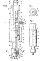
- the tool generally designated 10, comprises a power unit 12, an elongated sleeve 14 attached to power unit 12 by sleeve extension member 16, and reversible adapter 18 attached to the lower end of sleeve 14, Fig. 1.
- Sleeve 14, sleeve extension member 16 and adapter 18 are caused to rotate by power unit 12.
- Adapter 18 accommodates drill bit 80 at one end and a fastener driver 90 at the other end, Figs. 3 and 8.
- the tool 10' includes power unit 12', an elongated sleeve 15 attached to power unit 12', housing 17 attached to the lower end of sleeve 15, and adapter 18 attached to the lower end of housing 17.
- Sleeve 15, housing 17 and adapter 18 are all adapted to rotate with power unit 12'.
- Power unit 12 includes a standard chuck 20 with retractable jaws 21 to retain extension member 16 of sleeve 14.
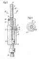
- Extension member 16 is tubular having a central bore 22 extending longitudinally thereof and terminating in a chamfer 23 internal of the sleeve 14.
- Extension member 16 is retained in sleeve 14 by means of set screw 24 which threadably engages tap 25 extending radially through the sleeve 14 into the sleeve's central opening 26.
- set screw 24 which threadably engages tap 25 extending radially through the sleeve 14 into the sleeve's central opening 26.
- extension member 16 is in its retracted position to accommodate a short drill yet still permit engagement by the chuck 20 so as to retain the sleeve 14 to the power unit 12.
- extension member 16 of Fig. 5 is shown in its fully extended position in which central bore 22 accommodates long drill bit 80'.
- Extension member 14 is adjustable between the retracted and extended positions by merely loosening the set screw 24 and manually sliding the extension member 14 to the desired length to accommodate the particular drill in the adapter when the adapter is in its fastener driver mode.
- Extension member 14 may have a circular cross section 27 as shown in Fig. 4 or a hexagonal cross section 28 as shown in Fig. 6. In the latter case set screw 24 will contact a flat surface.
- Slots 31 extend vertically through the sleeve 14 at the lower end thereof, Figs. 3 and 7. Attached within the slots 31 by means of a pin 32 is a latch member 33. Latch member 33 terminates in a handle 34 at one end and in an inwardly extending finger 35 at the other end. Coil spring 36 is attached to sleeve 14 and is housed within groove 37 of handle 34 so as to urge the finger end 35 into a closed or converging position.
- handle 34 of latch member 33 is depressed and either end of adapter 18 is inserted into sleeve 14 until finger 35 engages into external groove 43 of body member 40.
- Adapter 18 is inserted into sleeve 14 so that the adapter 18 rotates with sleeve 14 during operation.
- handle 34 is depressed and adapter 18 is removed and reversed so that the torquing end of the adapter 18 extends outward from the sleeve 14 so the threaded anchor can be properly set. In this position, the drill bit is safely out of the way within the internal bore of the sleeve 14.
- the same latch mechanism is located at the distal end of housing 17, Fig. 2.
- the adapter 18 comprises an elongated cylindrical body 40 having an enlarged cylindrical section 41 inward of one end and an enlarged cylindrical section 41' inward of the other end, Fig. 7. Each enlarged section defines a shoulder 43 against which finger 35 of latch member 33 engages so as to retain the adapter 18 in the sleeve extension 14.
- Body 40 includes an inwardly extending bore 44 at one end, and an inwardly extending bore 45 and counterbore 45' at the other end.
- Tap hole 47 is radially directed through the body 40 into bore 44 and tap hole 47' is radially directed through the body 40 into the bore 45.
- Bore 45 terminates in an internally tapped section 48.
- a clear through central opening 49 extends through the body and houses a quick release mechanism 50 to be described hereinafter.
- a driver 70 fits within the bore 45, Fig. 8.
- Driver 70 includes a section formed of a hex wall 71 and terminates in a fastener engaging member 72.
- An internal alien head set screw 73 engages the internal tap 48.
- Driver 70 abuts set screw 73 in end to end relationship and therefore set screw 73 provides a depth adjustment for the driver 70.
- a set screw 74 threads into tap 47 and engages one of the faces of the hex wall 71 to retain the driver 70 in place.
- driver 70 To adjust the depth of the driver 70, set screw 74 is loosened and the driver 70 is removed from the body 40. Thereafter, set screw 73 is advanced or retreated by means of an alien head wrench inserted in bore 45. Thereafter, driver 70 is inserted back into bore 45 and in abutting end to end relationship with set screw 73. Set screw 74 is then tightened to retain driver 70 in place. It will be recognized that driver 70 may terminate in a wrenching member such as a socket as well as the driver type illustrated.
- a bore 44 extends in the opposite end of the adapter 18 from bore 45 to accommodate a drill bit 80.
- the lower portion 44' of bore 44 has a D-shaped cross section.
- adapter 18 includes flat surface 46. Washer 59 is disposed along drill bit 80 so that it abuts the lower surface 42 of adapter 18.
- the drill bit 80 includes a flattened shank 81 of hemispherical cross section spaced between flattened shank 82 and the end section 83, Figs. 9 and 10.
- Flattened shank 82 having a D-shaped cross section corresponding to that of portion 44' of bore 44 in adapter 18 is spaced between drilling portion 84 and flattened shank 81, Figs. 10 and 12.
- Flattened shank 82 includes flat surface 85 and shoulder 86 formed between surface 85 and drilling portion 84.
- the quick release mechanism is housed within an opening 49 extending radially through the adapter 18 and into the bore 44, Figs. 8 and 9.
- the major component of the quick release mechanism is the shuttle 50, Fig. 9.
- Shuttle 50 includes an enlarged central section 53 which is dimensioned for sliding engagement within opening 49 of adapter 18.
- a lug 51 extends outwardly from central section 53 at one end and a reduced end section 55 including an axial threaded bore 56 extends outwardly from the other end.
- a retaining slot 52 is located along a portion of the central enlarged section 53.
- a central opening 54 extends through the central section 53 and in communication with bore 56.
- a set screw 58 extends through adapter 18 and terminates in slot 52 of shuttle 50 so as to retain shuttle 50 within opening 49.
- Lug 51 extends out of opening 49 in adapter 18, Fig. 9.
- Shuttle 50 is spring loaded by means of coil spring 62 housed between shoulder 57 of shuttle 50 and shoulder 60 formed within the opening 54 and internal of the adapter 18.
- An appropriately tipped set screw 61 threadably engages tap 56 in the reduced end section 55 of shuttle 50 so as to extend into the clear through opening 54. Set screw 61 permits adjustment of the shuttle 50 within the adapter 18.
- lug 51 is depressed inward causing compaction of coil spring 62.
- the drill 80 is positioned in the drill bore 44 past opening 54 of the shuttle 50 so that surface 85 of drill bit contacts surface 46 of adapter 18 and shoulder 86 of drill bit 80 contacts the lower outer surface 42 of adapter 40.
- Shuttle 50 is then released causing the set screw 61 to contact drill bit 80 along the flattened shank 81.
- the contact between the set screw 61 and the flattened surface 81 of the drill 80 causes the drill 80 to be retained within the adapter 18.
- the contact between surfaces 42 and 43 of adapter 18 and surfaces 85 and 86 of the drill 80 causes torque to be transmitted from adapter 18 to drill 80.
- drill 80 will rotate with adapter 18.
- lug 51 is depressed, permitting drill 80 to be easily removed and replaced.
- Such a quick release mechanism could also be employed at the fastener driver end of the adapter. However, it is more practical at the drill bit end because of the more unexpected and greater need to change the drill bit.
Landscapes
- Engineering & Computer Science (AREA)
- Mechanical Engineering (AREA)
- Drilling And Boring (AREA)
- Processing Of Stones Or Stones Resemblance Materials (AREA)
- Gripping On Spindles (AREA)
- Drilling Tools (AREA)
Applications Claiming Priority (8)
| Application Number | Priority Date | Filing Date | Title |
|---|---|---|---|
| US35322382A | 1982-03-01 | 1982-03-01 | |
| US353223 | 1982-03-01 | ||
| US437542 | 1982-10-29 | ||
| US06/437,542 US4605348A (en) | 1982-10-29 | 1982-10-29 | Quick release adapter |
| US45576083A | 1983-01-05 | 1983-01-05 | |
| US455760 | 1983-01-05 | ||
| US06/466,637 US4491443A (en) | 1982-10-29 | 1983-02-18 | Modified quick release adapter |
| US466637 | 1999-12-17 |
Publications (2)
| Publication Number | Publication Date |
|---|---|
| EP0087972A2 true EP0087972A2 (de) | 1983-09-07 |
| EP0087972A3 EP0087972A3 (de) | 1986-01-08 |
Family
ID=27502851
Family Applications (1)
| Application Number | Title | Priority Date | Filing Date |
|---|---|---|---|
| EP83301064A Withdrawn EP0087972A3 (de) | 1982-03-01 | 1983-02-28 | Zusatzeinrichtung für kraftangetriebenes Werkzeug |
Country Status (3)
| Country | Link |
|---|---|
| EP (1) | EP0087972A3 (de) |
| AU (1) | AU1199183A (de) |
| CA (1) | CA1191368A (de) |
Cited By (5)
| Publication number | Priority date | Publication date | Assignee | Title |
|---|---|---|---|---|
| EP0199842A1 (de) * | 1985-05-02 | 1986-11-05 | Licentia Patent-Verwaltungs-GmbH | Elektropneumatischer Drehschlagbohrhammer |
| US4725173A (en) * | 1985-05-08 | 1988-02-16 | Santrade Limited | Tool coupling device |
| EP0685300A1 (de) * | 1994-05-02 | 1995-12-06 | Matthew B. Jore | Umkehrbares Bohrantriebswerkzeug |
| TWI381916B (zh) * | 2009-01-09 | 2013-01-11 | Ho Tien Chen | 可調式鑽孔/倒角/鎖螺絲工具組 |
| CN109077777A (zh) * | 2018-10-19 | 2018-12-25 | 北京天星博迈迪医疗器械有限公司 | 深度可控钻孔装置及其钻头组件 |
Families Citing this family (1)
| Publication number | Priority date | Publication date | Assignee | Title |
|---|---|---|---|---|
| CN104439425A (zh) * | 2014-10-30 | 2015-03-25 | 东莞市青麦田数码科技有限公司 | 一种钻床钻孔深度定位装置 |
Family Cites Families (4)
| Publication number | Priority date | Publication date | Assignee | Title |
|---|---|---|---|---|
| FR1103112A (fr) * | 1954-04-15 | 1955-10-31 | Fixation des tamponnoirs dans les manches | |
| US3023015A (en) * | 1960-01-05 | 1962-02-27 | Melvin W Pankow | Reversible bit drill attachment |
| DE2022372A1 (de) * | 1970-05-08 | 1971-12-02 | Total Foerstner & Co | Geraet zum Eindringen in ein Brandgebiet |
| US3965510A (en) * | 1975-05-09 | 1976-06-29 | Illinois Tool Works Inc. | Combination drilling and wrenching tool |
-
1983
- 1983-02-28 EP EP83301064A patent/EP0087972A3/de not_active Withdrawn
- 1983-02-28 CA CA000422481A patent/CA1191368A/en not_active Expired
- 1983-03-02 AU AU11991/83A patent/AU1199183A/en not_active Abandoned
Cited By (6)
| Publication number | Priority date | Publication date | Assignee | Title |
|---|---|---|---|---|
| EP0199842A1 (de) * | 1985-05-02 | 1986-11-05 | Licentia Patent-Verwaltungs-GmbH | Elektropneumatischer Drehschlagbohrhammer |
| US4725173A (en) * | 1985-05-08 | 1988-02-16 | Santrade Limited | Tool coupling device |
| EP0685300A1 (de) * | 1994-05-02 | 1995-12-06 | Matthew B. Jore | Umkehrbares Bohrantriebswerkzeug |
| TWI381916B (zh) * | 2009-01-09 | 2013-01-11 | Ho Tien Chen | 可調式鑽孔/倒角/鎖螺絲工具組 |
| CN109077777A (zh) * | 2018-10-19 | 2018-12-25 | 北京天星博迈迪医疗器械有限公司 | 深度可控钻孔装置及其钻头组件 |
| CN109077777B (zh) * | 2018-10-19 | 2024-05-17 | 北京天星博迈迪医疗器械有限公司 | 深度可控钻孔装置及其钻头组件 |
Also Published As
| Publication number | Publication date |
|---|---|
| AU1199183A (en) | 1983-09-08 |
| EP0087972A3 (de) | 1986-01-08 |
| CA1191368A (en) | 1985-08-06 |
Similar Documents
| Publication | Publication Date | Title |
|---|---|---|
| US6176654B1 (en) | Reversible drill/driver tool | |
| US5470180A (en) | Reversible drill/driver tool | |
| US4605348A (en) | Quick release adapter | |
| US4491443A (en) | Modified quick release adapter | |
| US5954463A (en) | Reversible drill driver tool | |
| US4296656A (en) | Driver bit attachment | |
| US4512693A (en) | Reversible drill and drive tool holder | |
| CA2311956C (en) | Drilling and fastener driving tool | |
| CA2315918C (en) | Tool device with reversible drill bit/screw bit | |
| EP1878524B1 (de) | Antriebswerkzeuganordung | |
| US4944641A (en) | Clutch engager sleeve | |
| US8844941B1 (en) | Adaptor for holding a threading device | |
| US4224969A (en) | Universal chuck adaptor | |
| CA2651819A1 (en) | Flexible and extendable drill bit assembly | |
| US6877937B2 (en) | Reversible drill/driver tool | |
| CA1191368A (en) | Power tool adapter assembly | |
| US5711043A (en) | Set tool and cap | |
| US4934717A (en) | Quick exchange tool holder device | |
| GB2137912A (en) | Combined screw-driver attachment and power drill | |
| US4550476A (en) | Adjustment means for a driver bit | |
| US5015129A (en) | Adapter for battery-powered screwdriver to attach drill chuck | |
| US4062078A (en) | Hand drill and adapter tool | |
| EP4714578A1 (de) | Kombiniertes bohr- und schraubwerkzeug | |
| HK1003204A (en) | Reversible drill/driver tool |
Legal Events
| Date | Code | Title | Description |
|---|---|---|---|
| PUAI | Public reference made under article 153(3) epc to a published international application that has entered the european phase |
Free format text: ORIGINAL CODE: 0009012 |
|
| AK | Designated contracting states |
Designated state(s): CH DE FR GB LI SE |
|
| PUAL | Search report despatched |
Free format text: ORIGINAL CODE: 0009013 |
|
| AK | Designated contracting states |
Designated state(s): CH DE FR GB LI SE |
|
| STAA | Information on the status of an ep patent application or granted ep patent |
Free format text: STATUS: THE APPLICATION IS DEEMED TO BE WITHDRAWN |
|
| 18D | Application deemed to be withdrawn |
Effective date: 19860909 |
|
| RIN1 | Information on inventor provided before grant (corrected) |
Inventor name: DECARO, CHARLES JAMES |