EP0088264B1 - Câbles avec diélectrique extrudé - Google Patents
Câbles avec diélectrique extrudé Download PDFInfo
- Publication number
- EP0088264B1 EP0088264B1 EP83101592A EP83101592A EP0088264B1 EP 0088264 B1 EP0088264 B1 EP 0088264B1 EP 83101592 A EP83101592 A EP 83101592A EP 83101592 A EP83101592 A EP 83101592A EP 0088264 B1 EP0088264 B1 EP 0088264B1
- Authority
- EP
- European Patent Office
- Prior art keywords
- joint
- cable
- extruder
- dielectric
- point
- Prior art date
- Legal status (The legal status is an assumption and is not a legal conclusion. Google has not performed a legal analysis and makes no representation as to the accuracy of the status listed.)
- Expired
Links
- 238000000034 method Methods 0.000 claims abstract description 10
- 238000001125 extrusion Methods 0.000 claims abstract description 8
- 239000004020 conductor Substances 0.000 claims description 7
- 238000004519 manufacturing process Methods 0.000 claims description 6
- 239000003989 dielectric material Substances 0.000 claims description 3
- 230000003287 optical effect Effects 0.000 abstract description 9
- 239000013307 optical fiber Substances 0.000 abstract description 6
- XLYOFNOQVPJJNP-UHFFFAOYSA-N water Substances O XLYOFNOQVPJJNP-UHFFFAOYSA-N 0.000 description 4
- 239000004033 plastic Substances 0.000 description 3
- 229920003023 plastic Polymers 0.000 description 3
- 239000004411 aluminium Substances 0.000 description 2
- 229910052782 aluminium Inorganic materials 0.000 description 2
- XAGFODPZIPBFFR-UHFFFAOYSA-N aluminium Chemical compound [Al] XAGFODPZIPBFFR-UHFFFAOYSA-N 0.000 description 2
- 230000000903 blocking effect Effects 0.000 description 2
- 150000001875 compounds Chemical class 0.000 description 2
- 239000000835 fiber Substances 0.000 description 2
- 239000000463 material Substances 0.000 description 2
- 229920000573 polyethylene Polymers 0.000 description 2
- RYGMFSIKBFXOCR-UHFFFAOYSA-N Copper Chemical compound [Cu] RYGMFSIKBFXOCR-UHFFFAOYSA-N 0.000 description 1
- 229920000271 Kevlar® Polymers 0.000 description 1
- 239000004698 Polyethylene Substances 0.000 description 1
- 229910000831 Steel Inorganic materials 0.000 description 1
- 230000003466 anti-cipated effect Effects 0.000 description 1
- 239000011248 coating agent Substances 0.000 description 1
- 238000000576 coating method Methods 0.000 description 1
- 229910052802 copper Inorganic materials 0.000 description 1
- 239000010949 copper Substances 0.000 description 1
- 238000010586 diagram Methods 0.000 description 1
- 230000000694 effects Effects 0.000 description 1
- 238000010292 electrical insulation Methods 0.000 description 1
- 230000008595 infiltration Effects 0.000 description 1
- 238000001764 infiltration Methods 0.000 description 1
- 238000009413 insulation Methods 0.000 description 1
- 239000004761 kevlar Substances 0.000 description 1
- 229910052751 metal Inorganic materials 0.000 description 1
- 239000002184 metal Substances 0.000 description 1
- -1 polyethylene Polymers 0.000 description 1
- 238000007789 sealing Methods 0.000 description 1
- 239000010959 steel Substances 0.000 description 1
Images

Classifications
-
- G—PHYSICS
- G02—OPTICS
- G02B—OPTICAL ELEMENTS, SYSTEMS OR APPARATUS
- G02B6/00—Light guides; Structural details of arrangements comprising light guides and other optical elements, e.g. couplings
- G02B6/44—Mechanical structures for providing tensile strength and external protection for fibres, e.g. optical transmission cables
- G02B6/4479—Manufacturing methods of optical cables
- G02B6/4486—Protective covering
-
- B—PERFORMING OPERATIONS; TRANSPORTING
- B29—WORKING OF PLASTICS; WORKING OF SUBSTANCES IN A PLASTIC STATE IN GENERAL
- B29C—SHAPING OR JOINING OF PLASTICS; SHAPING OF MATERIAL IN A PLASTIC STATE, NOT OTHERWISE PROVIDED FOR; AFTER-TREATMENT OF THE SHAPED PRODUCTS, e.g. REPAIRING
- B29C48/00—Extrusion moulding, i.e. expressing the moulding material through a die or nozzle which imparts the desired form; Apparatus therefor
- B29C48/03—Extrusion moulding, i.e. expressing the moulding material through a die or nozzle which imparts the desired form; Apparatus therefor characterised by the shape of the extruded material at extrusion
- B29C48/06—Rod-shaped
-
- B—PERFORMING OPERATIONS; TRANSPORTING
- B29—WORKING OF PLASTICS; WORKING OF SUBSTANCES IN A PLASTIC STATE IN GENERAL
- B29C—SHAPING OR JOINING OF PLASTICS; SHAPING OF MATERIAL IN A PLASTIC STATE, NOT OTHERWISE PROVIDED FOR; AFTER-TREATMENT OF THE SHAPED PRODUCTS, e.g. REPAIRING
- B29C48/00—Extrusion moulding, i.e. expressing the moulding material through a die or nozzle which imparts the desired form; Apparatus therefor
- B29C48/15—Extrusion moulding, i.e. expressing the moulding material through a die or nozzle which imparts the desired form; Apparatus therefor incorporating preformed parts or layers, e.g. extrusion moulding around inserts
-
- B—PERFORMING OPERATIONS; TRANSPORTING
- B29—WORKING OF PLASTICS; WORKING OF SUBSTANCES IN A PLASTIC STATE IN GENERAL
- B29C—SHAPING OR JOINING OF PLASTICS; SHAPING OF MATERIAL IN A PLASTIC STATE, NOT OTHERWISE PROVIDED FOR; AFTER-TREATMENT OF THE SHAPED PRODUCTS, e.g. REPAIRING
- B29C48/00—Extrusion moulding, i.e. expressing the moulding material through a die or nozzle which imparts the desired form; Apparatus therefor
- B29C48/25—Component parts, details or accessories; Auxiliary operations
- B29C48/30—Extrusion nozzles or dies
- B29C48/32—Extrusion nozzles or dies with annular openings, e.g. for forming tubular articles
-
- H—ELECTRICITY
- H01—ELECTRIC ELEMENTS
- H01B—CABLES; CONDUCTORS; INSULATORS; SELECTION OF MATERIALS FOR THEIR CONDUCTIVE, INSULATING OR DIELECTRIC PROPERTIES
- H01B13/00—Apparatus or processes specially adapted for manufacturing conductors or cables
- H01B13/06—Insulating conductors or cables
- H01B13/14—Insulating conductors or cables by extrusion
- H01B13/143—Insulating conductors or cables by extrusion with a special opening of the extrusion head
-
- B—PERFORMING OPERATIONS; TRANSPORTING
- B29—WORKING OF PLASTICS; WORKING OF SUBSTANCES IN A PLASTIC STATE IN GENERAL
- B29C—SHAPING OR JOINING OF PLASTICS; SHAPING OF MATERIAL IN A PLASTIC STATE, NOT OTHERWISE PROVIDED FOR; AFTER-TREATMENT OF THE SHAPED PRODUCTS, e.g. REPAIRING
- B29C48/00—Extrusion moulding, i.e. expressing the moulding material through a die or nozzle which imparts the desired form; Apparatus therefor
- B29C48/03—Extrusion moulding, i.e. expressing the moulding material through a die or nozzle which imparts the desired form; Apparatus therefor characterised by the shape of the extruded material at extrusion
- B29C48/05—Filamentary, e.g. strands
Definitions
- This invention relates to a cable with extruded dielectric layer, particularly but not exclusively an optical cable for submerged telecommunication systems and to a method and apparatus of making such a cable.
- a cable with extruded dielectric layer particularly but not exclusively an optical cable for submerged telecommunication systems
- a method and apparatus of making such a cable At certain points during the manufacture of the cable it becomes necessary to make a joint in the optical fibres in the centre of the cable.
- the centre conductor and extrusion processes have a buffer stock of stored cable lengths between them, and these lengths are jointed together using a joint of the same diameter which requires subsequent rectification to restore the centre conductor to its required characteristics.
- a cable of this kind is disclosed in DE-A-28 51 955.
- a connection of the ends of two cables which is obviously not represented correctly by the corresponding Fig.
- the cable sheath is jointed at .the same place as the cable core and the armouring layer. It is the object of the invention to provide a cable which is watertight at the joints. In particular it is a requirement that the thickness of the dielectric layer should remain constant and should not be less than a predetermined minimum thickness in order to provide the necessary dielectric properties.
- a cable comprising a cable core with at least one conductor, a tensile strength member and a dielectric layer extruded over the cable core and/or strength member, wherein the cable core and/or strength member consists of pieces which are jointed to each other and the dielectric layer is uninterrupted over the length of the cable.
- the method of making the cable is characterized in effecting a joint in the conductor and/or strength member prior to extrusion of the dielectric layer, and passing the joint through an extruder so that the dielectric layer is extruded over the joint, the extruder head having a variable-size extruder point which accommodates the joint as it passes through the extruder.
- apparatus for extruding dielectric material over a jointed cable comprising an extruder point having a variable orifice defined by a number of segments fitted together to form a substantially frusto-conical extruder point, and means for urging the segments together to define a nominal extruder point orifice.
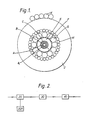
- the cable comprises an optical fibre package at the centre consisting of a package strength member A made of high tensile steel wire which may, if desired, be copper plated to improve its electrical conductivity, and coated with a plastics coating A i .
- a package strength member A made of high tensile steel wire which may, if desired, be copper plated to improve its electrical conductivity, and coated with a plastics coating A i .
- Around the package strength member A are eight single mode secondary coated optical fibres B which are held in a package whipping C.
- a fibrous Kevlar ribbon which in the particular embodiment described has about 200 denier.
- the fibre package and the annular gap between the fibre package and the internal bore of a tubular member E are impregnated and filled respectively with a water blocking compound.
- the main function of this water blocking compound is to substantially restrict longitudinal infiltration of water along the core should the cable become damaged.
- a laminate sealing strip F Around the core member E is a laminate sealing strip F.
- This is a heat sealable plastics tape, e.g. ethyl acrylic material bonded to both sides of a thin aluminium tape, and is heat sealed to member E to form an hermetic seal around it.
- the tubular core E Around the tubular core E are applied two layers of tensile strength elements for the cable, G and H respectively, which bridge against one another so that there is formed a crush-resistant electrically conductive tensile strength member which provides the tensile strength the cable is required to have. For submarine cables this could be of the order of 18 tons breaking strength. It is also crush-resistant so that the fibres loosely held in the central bore of the tubular member are substantially free of compressive stresses in use of the cable.
- a polyethylene sheath J Extruded around the outside of and directly onto the outer layer of strength member wires is a polyethylene sheath J which forms an electrical insulation between the outside and any electric power or electric signal which is, in use of the cable, transmitted along the conductive central core E.
- One or more armouring layers K can be applied to the outside of the insulation J.
- the optical fibre package comprises eight optical fibres B with a central king wire A.
- This package enters the partially opened C-shaped tube E at 20A and at station 20 the tube is closed around the optical fibers.
- the closed aluminium C-section tube housing the optical fibres passes through to station 30 at which the strength members G and H are applied.
- armouring wires could be applied around the outside of the dielectric J in order to protect the cable in shallow water.
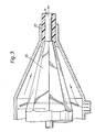
- variable orifice extruder point is shown in detail in Figures 3 and 4 and reference will now be made to those Figures.
- Fig. 4A is a front perspective view of one of the segments 50 and Fig. 4B shows an underneath plan view of the same segment.
- Fig. 4 simply shows the eight segments 50 fitted together and viewed from the front i.e. the point at which the cable leaves the extruder head.
- variable orifice extruder comprises a plurality of segments 50 which are made of metal and are generally triangular in shape.
- the segments fit together to form a frusto-conical outer surface 51.
- Each has a first edge surface 52, and an inner face surface 53 which embraces the surface of the strength members H as the strength members and the core of the cable pass through the extruder, and an opposite under edge surface 55.
- Each segment is arranged to pivot at its end remote from the extruder point about an axis which is substantially parallel to the surface 53 and bisects the angle between edges 52 and 53A.
- a rib 54 which performs two functions. Firstly it has a taper 54b with respect to the axis of the cable which is effective to provide a "run-up" against the cable passing through the extruder head. Secondly the rib 54 provides an abutment 54a against which the adjacent segment will rest in its normal position.
- a strong circumferential spring (not shown in the drawing) tends to force all the segment tips radially inwardly about their pivots until the abutments 54a resist further inward motion so that the orifice of the extruder head defines a slab-sided circle which just fits the outer surface of the strength members H on the cable core.
- This slab-sided circle is indicated by the reference 56 in Fig. 4.
- Each segment edge which embraces the next segment performs a "wiping action" and is effective to seal the edges from intrusion by extruder material, and at the same time the wiping action tends to keep the edges clean.
- the movement anticipated can correspond to a change in radial dimension of around 5 times the diameter of the strength member.
- the plastics dielectric will be thinner at the point of the bulge because the outer diameter of the extruder head or die represented by the cylindrical portion 57, remains constant. If necessary this can be made good by bonding further dielectric material over the thin dielectric to reinstate the required thickness or, if the internal joint in the fibres and! or strength member is only temporary, then a jointing operation can be performed followed by reinstatement of the sheath.
- the invention enables the extrusion process to work continuously and not be stopped when a joint, temporary or permanent, is made in the cable and prior to reaching the extruder point.
- variable die 57 could be constructed on the same lines as the extruder point so that just before the "bulge” reaches the extruder point, the die opens to provide an increase in dielectric thickness, and closes at the same position behind the "bulge” after it has passed through.
- the die and extruder point could be mechanically linked to achieve this, or hydraulically and electronically controlled to achieve the desired opening.
- the die would open by the same amount or more than the extruder point, and may open to a point where the extrudate no longer contacts the die, in which case vacuum in the extruder head would be relied upon to draw the extrudate down onto the strength member.
- the effect of the die would be to maintain the same dielectric thickness over the joint as over the rest of the cable.
Landscapes
- Engineering & Computer Science (AREA)
- Mechanical Engineering (AREA)
- Manufacturing & Machinery (AREA)
- Physics & Mathematics (AREA)
- General Physics & Mathematics (AREA)
- Optics & Photonics (AREA)
- Extrusion Moulding Of Plastics Or The Like (AREA)
- Communication Cables (AREA)
- Manufacturing Of Electric Cables (AREA)
- Insulated Conductors (AREA)
Claims (11)
Priority Applications (1)
| Application Number | Priority Date | Filing Date | Title |
|---|---|---|---|
| AT83101592T ATE19750T1 (de) | 1982-03-04 | 1983-02-19 | Kabel mit extrudiertem dielektrikum. |
Applications Claiming Priority (2)
| Application Number | Priority Date | Filing Date | Title |
|---|---|---|---|
| GB08206374A GB2116901B (en) | 1982-03-04 | 1982-03-04 | Extruding a dielectric sheath around a joint in an optical fibre cable |
| GB8206374 | 1982-03-04 |
Publications (3)
| Publication Number | Publication Date |
|---|---|
| EP0088264A1 EP0088264A1 (fr) | 1983-09-14 |
| EP0088264B1 true EP0088264B1 (fr) | 1986-05-14 |
| EP0088264B2 EP0088264B2 (fr) | 1989-08-30 |
Family
ID=10528782
Family Applications (1)
| Application Number | Title | Priority Date | Filing Date |
|---|---|---|---|
| EP83101592A Expired EP0088264B2 (fr) | 1982-03-04 | 1983-02-19 | Câbles avec diélectrique extrudé |
Country Status (9)
| Country | Link |
|---|---|
| EP (1) | EP0088264B2 (fr) |
| AT (1) | ATE19750T1 (fr) |
| AU (1) | AU559890B2 (fr) |
| DE (1) | DE3363476D1 (fr) |
| ES (1) | ES520335A0 (fr) |
| GB (1) | GB2116901B (fr) |
| IT (1) | IT1237336B (fr) |
| NZ (1) | NZ203390A (fr) |
| ZA (1) | ZA831516B (fr) |
Cited By (1)
| Publication number | Priority date | Publication date | Assignee | Title |
|---|---|---|---|---|
| US6254924B1 (en) | 1996-01-04 | 2001-07-03 | General Cable Technologies Corporation | Paired electrical cable having improved transmission properties and method for making same |
Families Citing this family (2)
| Publication number | Priority date | Publication date | Assignee | Title |
|---|---|---|---|---|
| GB2128357B (en) * | 1982-10-06 | 1986-05-21 | Standard Telephones Cables Ltd | Optical fibre cables |
| GB2191872B (en) * | 1986-06-17 | 1989-12-28 | Stc Plc | Optical fibre cables |
Family Cites Families (7)
| Publication number | Priority date | Publication date | Assignee | Title |
|---|---|---|---|---|
| GB420552A (en) * | 1933-12-14 | 1934-12-04 | James Gillespie | Machines for coating or covering welding rods used for welding operations |
| GB493015A (en) * | 1937-04-09 | 1938-09-30 | Intercito Holding | Method of and machine for making electrodes for electric arc welding |
| GB649873A (en) * | 1946-02-01 | 1951-02-07 | Pirelli General Cable Works | Improvements in or relating to multiple extrusion dies for applying insulation to the cores of electric cables |
| DE1231419B (de) * | 1958-09-30 | 1966-12-29 | Siemens Ag | Vorrichtung zum elastischen Fuehren eines Stranges innerhalb eines den Strang beruehrenden, im Spritzkopf einer Schneckenstrangpresse angeordneten Nippels |
| GB1057204A (en) * | 1965-05-14 | 1967-02-01 | Goldwyn Weekley | Coating apparatus and method therefor |
| GB1075258A (en) * | 1965-12-08 | 1967-07-12 | Pipe Linings Inc | Apparatus for extrusion coating of pipe |
| IT1121754B (it) * | 1977-12-05 | 1986-04-23 | Int Standard Electric Corp | Cavo per comunicazione ottica |
-
1982
- 1982-03-04 GB GB08206374A patent/GB2116901B/en not_active Expired
-
1983
- 1983-02-19 AT AT83101592T patent/ATE19750T1/de not_active IP Right Cessation
- 1983-02-19 EP EP83101592A patent/EP0088264B2/fr not_active Expired
- 1983-02-19 DE DE8383101592T patent/DE3363476D1/de not_active Expired
- 1983-02-24 NZ NZ203390A patent/NZ203390A/en unknown
- 1983-03-01 AU AU11944/83A patent/AU559890B2/en not_active Ceased
- 1983-03-04 ZA ZA831516A patent/ZA831516B/xx unknown
- 1983-03-04 IT IT8319896A patent/IT1237336B/it active
- 1983-03-04 ES ES520335A patent/ES520335A0/es active Granted
Cited By (1)
| Publication number | Priority date | Publication date | Assignee | Title |
|---|---|---|---|---|
| US6254924B1 (en) | 1996-01-04 | 2001-07-03 | General Cable Technologies Corporation | Paired electrical cable having improved transmission properties and method for making same |
Also Published As
| Publication number | Publication date |
|---|---|
| IT1237336B (it) | 1993-05-31 |
| ES8402944A1 (es) | 1984-03-16 |
| AU1194483A (en) | 1983-09-08 |
| EP0088264B2 (fr) | 1989-08-30 |
| IT8319896A0 (it) | 1983-03-04 |
| ES520335A0 (es) | 1984-03-16 |
| GB2116901B (en) | 1986-10-29 |
| AU559890B2 (en) | 1987-03-26 |
| NZ203390A (en) | 1985-11-08 |
| DE3363476D1 (en) | 1986-06-19 |
| ZA831516B (en) | 1983-11-30 |
| ATE19750T1 (de) | 1986-05-15 |
| GB2116901A (en) | 1983-10-05 |
| EP0088264A1 (fr) | 1983-09-14 |
Similar Documents
| Publication | Publication Date | Title |
|---|---|---|
| US4577925A (en) | Optical fiber communication cables and method and apparatus for assembling same | |
| US4729629A (en) | Bonded sheath cable with lubricant over seam | |
| US4257675A (en) | Optical-fiber submarine cable and manufacturing method thereof | |
| US4227770A (en) | Submarine fiber optic cable | |
| CA1194714A (fr) | Ligne aerienne composite de transmission | |
| US4422718A (en) | Submarine optical fiber cable | |
| US4902097A (en) | Optical fibre cables | |
| EP0205268A2 (fr) | Ligne de transmission électrique | |
| US4484963A (en) | Method for fabricating an optical fiber cable | |
| JPH08327846A (ja) | ジョイントボックスを保護および絶縁するための方法 | |
| US4775213A (en) | Composite overhead stranded conductor having a filler between optical fibers and a protective tube | |
| EP0110507B1 (fr) | Câbles optiques | |
| CN1012024B (zh) | 具有光波导的通信光缆 | |
| US4688888A (en) | Optical cable | |
| GB2029047A (en) | Optical fibre submarina cable | |
| EP0088264B1 (fr) | Câbles avec diélectrique extrudé | |
| US4538881A (en) | Optical fiber cable including a strain equalizing adhesive which constrains optical loss | |
| GB2115172A (en) | Optical fibre cables | |
| US5778652A (en) | Cable with a sheath made of steel, and a method and apparatus for forming the cable | |
| US4832441A (en) | Optical fiber cable | |
| CA1229722A (fr) | Methode de fabrication de cables a fibres optiques | |
| EP0539915A1 (fr) | Câble composite à puissance | |
| JP2978104B2 (ja) | 自己支持型パイプ複合ケーブル | |
| EP0514091B1 (fr) | Câble fibre optique | |
| EP0137079A1 (fr) | Procédé et dispositif pour assembler un câble de communication avec plusieurs conducteurs de fibres optiques |
Legal Events
| Date | Code | Title | Description |
|---|---|---|---|
| PUAI | Public reference made under article 153(3) epc to a published international application that has entered the european phase |
Free format text: ORIGINAL CODE: 0009012 |
|
| AK | Designated contracting states |
Designated state(s): AT BE CH DE FR IT LI |
|
| RBV | Designated contracting states (corrected) |
Designated state(s): AT BE CH DE FR IT LI |
|
| 17P | Request for examination filed |
Effective date: 19831014 |
|
| GRAA | (expected) grant |
Free format text: ORIGINAL CODE: 0009210 |
|
| AK | Designated contracting states |
Kind code of ref document: B1 Designated state(s): AT BE CH DE FR IT LI |
|
| PG25 | Lapsed in a contracting state [announced via postgrant information from national office to epo] |
Ref country code: LI Effective date: 19860514 Ref country code: CH Effective date: 19860514 Ref country code: AT Effective date: 19860514 |
|
| REF | Corresponds to: |
Ref document number: 19750 Country of ref document: AT Date of ref document: 19860515 Kind code of ref document: T |
|
| REF | Corresponds to: |
Ref document number: 3363476 Country of ref document: DE Date of ref document: 19860619 |
|
| ITF | It: translation for a ep patent filed | ||
| ET | Fr: translation filed | ||
| BECN | Be: change of holder's name |
Effective date: 19860514 |
|
| PLBI | Opposition filed |
Free format text: ORIGINAL CODE: 0009260 |
|
| 26 | Opposition filed |
Opponent name: AEG KABEL AKTIENGESELLSCHAFT Effective date: 19870213 |
|
| REG | Reference to a national code |
Ref country code: CH Ref legal event code: PUE Owner name: STC PLC |
|
| BERE | Be: lapsed |
Owner name: STC P.L.C. Effective date: 19870228 |
|
| ITPR | It: changes in ownership of a european patent |
Owner name: CESSIONE;STC PLC |
|
| RAP2 | Party data changed (patent owner data changed or rights of a patent transferred) |
Owner name: STC PLC |
|
| REG | Reference to a national code |
Ref country code: FR Ref legal event code: TP |
|
| PGFP | Annual fee paid to national office [announced via postgrant information from national office to epo] |
Ref country code: AT Payment date: 19881207 Year of fee payment: 7 |
|
| PGFP | Annual fee paid to national office [announced via postgrant information from national office to epo] |
Ref country code: CH Payment date: 19881215 Year of fee payment: 7 |
|
| PGFP | Annual fee paid to national office [announced via postgrant information from national office to epo] |
Ref country code: FR Payment date: 19890227 Year of fee payment: 7 |
|
| PG25 | Lapsed in a contracting state [announced via postgrant information from national office to epo] |
Ref country code: BE Effective date: 19890228 |
|
| PUAH | Patent maintained in amended form |
Free format text: ORIGINAL CODE: 0009272 |
|
| STAA | Information on the status of an ep patent application or granted ep patent |
Free format text: STATUS: PATENT MAINTAINED AS AMENDED |
|
| 27A | Patent maintained in amended form |
Effective date: 19890830 |
|
| AK | Designated contracting states |
Kind code of ref document: B2 Designated state(s): AT BE CH DE FR IT LI |
|
| REG | Reference to a national code |
Ref country code: CH Ref legal event code: PL |
|
| EN3 | Fr: translation not filed ** decision concerning opposition | ||
| PGFP | Annual fee paid to national office [announced via postgrant information from national office to epo] |
Ref country code: DE Payment date: 19900430 Year of fee payment: 8 |
|
| PG25 | Lapsed in a contracting state [announced via postgrant information from national office to epo] |
Ref country code: FR Effective date: 19901031 |
|
| REG | Reference to a national code |
Ref country code: FR Ref legal event code: ST |
|
| PG25 | Lapsed in a contracting state [announced via postgrant information from national office to epo] |
Ref country code: DE Effective date: 19911101 |