EP0088410A1 - Connecteurs pour fibres optiques - Google Patents
Connecteurs pour fibres optiques Download PDFInfo
- Publication number
- EP0088410A1 EP0088410A1 EP83102166A EP83102166A EP0088410A1 EP 0088410 A1 EP0088410 A1 EP 0088410A1 EP 83102166 A EP83102166 A EP 83102166A EP 83102166 A EP83102166 A EP 83102166A EP 0088410 A1 EP0088410 A1 EP 0088410A1
- Authority
- EP
- European Patent Office
- Prior art keywords
- ferrule
- ferrules
- optical fiber
- fiber
- axis
- Prior art date
- Legal status (The legal status is an assumption and is not a legal conclusion. Google has not performed a legal analysis and makes no representation as to the accuracy of the status listed.)
- Granted
Links
- 239000013307 optical fiber Substances 0.000 title claims abstract description 39
- 239000000835 fiber Substances 0.000 claims abstract description 40
- 230000005540 biological transmission Effects 0.000 abstract description 3
- 230000008878 coupling Effects 0.000 description 12
- 238000010168 coupling process Methods 0.000 description 12
- 238000005859 coupling reaction Methods 0.000 description 12
- 239000011248 coating agent Substances 0.000 description 7
- 239000003795 chemical substances by application Substances 0.000 description 5
- 238000000576 coating method Methods 0.000 description 5
- 238000005253 cladding Methods 0.000 description 4
- 230000013011 mating Effects 0.000 description 3
- 239000004677 Nylon Substances 0.000 description 2
- 238000010276 construction Methods 0.000 description 2
- 238000011065 in-situ storage Methods 0.000 description 2
- 229920001778 nylon Polymers 0.000 description 2
- 230000003287 optical effect Effects 0.000 description 2
- 239000000853 adhesive Substances 0.000 description 1
- 238000004891 communication Methods 0.000 description 1
- 230000002950 deficient Effects 0.000 description 1
- 230000007774 longterm Effects 0.000 description 1
- 238000012423 maintenance Methods 0.000 description 1
- 239000000463 material Substances 0.000 description 1
- 230000004048 modification Effects 0.000 description 1
- 238000012986 modification Methods 0.000 description 1
- 230000010355 oscillation Effects 0.000 description 1
- 229920000915 polyvinyl chloride Polymers 0.000 description 1
- 239000004800 polyvinyl chloride Substances 0.000 description 1
- 230000000644 propagated effect Effects 0.000 description 1
- 230000001681 protective effect Effects 0.000 description 1
- 230000003014 reinforcing effect Effects 0.000 description 1
- 239000000126 substance Substances 0.000 description 1
Images



Classifications
-
- G—PHYSICS
- G02—OPTICS
- G02B—OPTICAL ELEMENTS, SYSTEMS OR APPARATUS
- G02B6/00—Light guides; Structural details of arrangements comprising light guides and other optical elements, e.g. couplings
- G02B6/24—Coupling light guides
- G02B6/36—Mechanical coupling means
- G02B6/38—Mechanical coupling means having fibre to fibre mating means
- G02B6/3807—Dismountable connectors, i.e. comprising plugs
- G02B6/381—Dismountable connectors, i.e. comprising plugs of the ferrule type, e.g. fibre ends embedded in ferrules, connecting a pair of fibres
- G02B6/3818—Dismountable connectors, i.e. comprising plugs of the ferrule type, e.g. fibre ends embedded in ferrules, connecting a pair of fibres of a low-reflection-loss type
- G02B6/3822—Dismountable connectors, i.e. comprising plugs of the ferrule type, e.g. fibre ends embedded in ferrules, connecting a pair of fibres of a low-reflection-loss type with beveled fibre ends
-
- G—PHYSICS
- G02—OPTICS
- G02B—OPTICAL ELEMENTS, SYSTEMS OR APPARATUS
- G02B6/00—Light guides; Structural details of arrangements comprising light guides and other optical elements, e.g. couplings
- G02B6/24—Coupling light guides
- G02B6/36—Mechanical coupling means
- G02B6/38—Mechanical coupling means having fibre to fibre mating means
- G02B6/3807—Dismountable connectors, i.e. comprising plugs
- G02B6/381—Dismountable connectors, i.e. comprising plugs of the ferrule type, e.g. fibre ends embedded in ferrules, connecting a pair of fibres
- G02B6/3825—Dismountable connectors, i.e. comprising plugs of the ferrule type, e.g. fibre ends embedded in ferrules, connecting a pair of fibres with an intermediate part, e.g. adapter, receptacle, linking two plugs
-
- G—PHYSICS
- G02—OPTICS
- G02B—OPTICAL ELEMENTS, SYSTEMS OR APPARATUS
- G02B6/00—Light guides; Structural details of arrangements comprising light guides and other optical elements, e.g. couplings
- G02B6/24—Coupling light guides
- G02B6/36—Mechanical coupling means
- G02B6/38—Mechanical coupling means having fibre to fibre mating means
- G02B6/3807—Dismountable connectors, i.e. comprising plugs
- G02B6/3833—Details of mounting fibres in ferrules; Assembly methods; Manufacture
- G02B6/3834—Means for centering or aligning the light guide within the ferrule
- G02B6/3835—Means for centering or aligning the light guide within the ferrule using discs, bushings or the like
-
- G—PHYSICS
- G02—OPTICS
- G02B—OPTICAL ELEMENTS, SYSTEMS OR APPARATUS
- G02B6/00—Light guides; Structural details of arrangements comprising light guides and other optical elements, e.g. couplings
- G02B6/24—Coupling light guides
- G02B6/36—Mechanical coupling means
- G02B6/38—Mechanical coupling means having fibre to fibre mating means
- G02B6/3807—Dismountable connectors, i.e. comprising plugs
- G02B6/389—Dismountable connectors, i.e. comprising plugs characterised by the method of fastening connecting plugs and sockets, e.g. screw- or nut-lock, snap-in, bayonet type
- G02B6/3894—Screw-lock type
Definitions
- the present invention generally relates to a connector and, more specifically, to an optical fiber connector for coupling a pair of single optical fibers.
- Fresnel reflection caused on an optical fiber end surface in an optical fiber connector has been becoming a critical factor for determination of the transmission quality in optical communication systems. More particularly, the feedback of reflected light to a laser diode makes oscillation characteristics unstable and light reflected returns to a light receiving element again to deteriorate S/N.
- an index matching agent is inserted between end surfaces of two optical fibers; (2) end surface of optical fibers are coated with a non-reflecting film (Jap. Utility Model Application Laid-open, Sho 56-88217); and (3) either the end surfaces of optical fibers or the end surfaces of ferrule are inclined to make a reflection angle larger than the numerical aperture of optical fibers so as to leak the light (refer to Jap. Patent Application Laid-open Sho 53-149346 and 54-150142).
- the index matching agent and the non-reflection coating aim at reducing reflection per se while the slant configuration of end surfaces intends to prevent propagation of reflected light.
- the first means lacks reliability, and is inconvenient in mating and/or unmating.
- the second means is defective in that it is practically impossible to lower the refractive index of the coated films to less than 1%, and that such coating might become peeled off when fibers are coupled in abutment.
- the third means is also disadvantageous in that end surfaces of fibers must be bevelled accurately with a particular angle and, further at the time of mating of two fibers, and surfaces of each fiber should be accurately aligned anglewise.
- the principal object of the present invention is to provide a novel structure of an optical fiber connector which can obviate problems heretofore encountered in prior art.
- An optical fiber connector assembly for coupling a pair of optical fibers in an aligned position comprises: first and second ferrules each adapted to be fixed to the end of an optical fiber, each of the first and second ferrules being formed with a first aperture extending a certain distance, from a front flat end of the ferrule to a rear flat end of ferrule, along a slant axis with a predetermined angle in respect of a ferrule axis and with a second aperture parallel to the ferrule axis extending from the rear flat end of the ferrule, the first aperture being shaped and dimensioned to permit a stripped end of a single optical fiber to be positioned within the first aperture, the fiber being so positioned that the fiber end and the front end are coplanar; and a receptacle body guiding the first and second ferrules, the first and second ferrules are positioned within the receptacle body so that the front flat ends of the first and second ferrul
- end surfaces of two ferrrules are constructed perpendicular to the axes thereof, two fibers are arranged in a manner that the axes are inclined in respect of ferrule axes, and ferrule end surfaces are made to contact and the axes of two fibers to form a straight line, thereby facilitating positional alignment of ferrules and grinding of ends as well as effectively preventing the feedback which otherwise is caused by Fresnel reflection.
- the second example of the prior art shown in Fig. 2 aims at suppressing reflection by coating the fiber ends with a non-reflection coating agent 9.
- the non-reflection coating agent 9 can theoretically prevent reflection, coating materials presently available can not reduce the refraction index to l% or less. The coating might peel off when fibers are abutted for connection.
- the third prior art shown in Fig. 3 is structured in a manner that the end surfaces 10 and 11 of the ferrules 1 and 5 and optical fiber end surfaces are bevelled accurately so as to leak the reflected light from the fiber end surfaces. Although it can leak reflected light, angular alignment between a pair of feri-ules or fibers is difficult and a slight misalignment which causes line contact, not surface contact, in engagement might damage fiber end surfaces when the ferrules are frequently mated/ unmated. It also requires special jigs and tools for in situ assembling of cable laying construction.
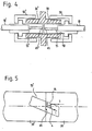
- the first embodiment of the optical fiber connector according to this invention includes two ferrules 30, 30' which respectively hold optical fibers 15, 15' therein and coupling nuts 50, 50' which fix two ferrules 30, 30' on a receptacle body 70.
- the ferrule 30 is formed with a first hole extending obliquely in respect of the ferrule axis from the center of an end surface 65 which is perpendicular to the ferrule axis.
- a second hole is bored in parallel to the ferrule axis to communicate with the first hole.
- a third hole having a diameter larger than that of the second hole is further provided.
- Ferrule 30' has a similar construction, and is located in a rotated position from the ferrule 30 by 180° so that the axes of the two fibers are arranged in a line and the line forms a certain angle in respect of the ferrule axis when two end surfaces 65, 65' of two ferrules 30, 30 1 are snugly mated inside the receptacle body,
- the light 1 which has passed the fiber 15 is reflected on the fiber end surface 65.
- the inclination of the fiber to the ferrule axis is so set that the reflection angle 4 to the surface 65 is not greater than the numerical aperture of the fiber, the reflected light will become a leak light 3 and will not return to inside the fiber.
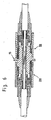
- the optical connector of embodying the present invention includes an adaptor 75, and a pair of plugs 100, 200 which are coupled from both sides with the adaptor.
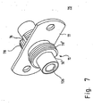
- the adaptor 75 comprises a receptacle body 70 having an axial bore 126 of uniform inner diameter mounted on a flange 77 and external threaded portions 78, 78'.
- the threaded portions are so positioned that axial grooves 76, 76 1 which are parallel to the axial direction will become symmetrical to each other in respect of the point where the axis and the flange cross each other.
- the axial grooves therefore are provided in a direction staggered by 180° from the outer periphery of the receptacle body.
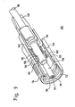
- a plug 100 includes a ferrule 120, a support body 170 for housing the ferrule, a stop nut 140 for fixing the ferrule on the support body and a coupling nut 150 to be coupled with the support body via a retainer 192 for connection with an adaptor.
- the optical fiber cable 110 comprises, from the core to outward, a single optical fiber 115, a nylon cladding 114 which acts as a protective jacket for the single strand, a tensile strength member 112, and an outer sheath 116 which is made of polyvinyl chloride and acts as a reinforcing member.
- the ferrule 120 is of a hollow cylindrical configuration comprising, from inside to axially outward, a first hollow axial bore 126, a second hollow axial bore 128 of a larger diameter than that of the first bore, and a third hollow axial bore 129 of a larger diameter than that of the second bore.
- the ferrule 120 forms, on the external side thereof from the tip end in circumferential direction, a first annual groove 122 and a second annual groove 124.
- the ferrule includes a ring 180 which is fixed along the first annular groove 122.
- the ring 180 has a flange 184 a portion of which defines a projection 182.
- the first axial bore 126 of the ferrule includes a hollow cylindrical member 160 which determines the direction of the axis of a single fiber strand on the tip end thereof.
- the inside of the hollow cylindrical member 160 is formed with a first bevel bore 162 which has a uniform diameter and is inclined by 10° in respect of the center axis in a manner that the tip end thereof is positioned at the center of the front end surface 165.
- a second bevel bore 162 extends from the center of the rear end to communicate with the first bevel bore.
- a capillary 161 of a diameter substantially identical to that of the first bevel bore is inserted from the front end of the hollow cylindrical member 160 and secured.
- the optical fiber cable 110 is processed to expose the single optical fiber strand in the end section, the nylon cladding in the first intermediate section and the tension member in the second intermediate section.
- the optical fiber is inserted into the ferrule 120 so that respective sections are positioned at the cylindrical member 160 in the first axial bore 126, the second and the third bore respectively and then are securely fixed.
- the optical fiber strand goes through the second bevel bore inside the cylindrical member 160 and reaches the capillary 164 which has an inner diameter substantially identical to that of the strand to be fixed therein with an adhesive agent.
- the fiber tip end, the ferrule end surface and the cylindrical member end surface are ground to form a coplanar perpendicular to the central axis of the ferrule.
- a projected member of a rubber holder 130 fixed on the fiber cable 110 is engaged within the second annular groove 124. The rubber holder acts as a buffer against the bend of the cable.
- the fiber thus assembled up to this stage is mounted with a stop nut 140 from the tip end of the ferrule, which is then covered by a coil spring 196 and a ring 180.
- the ring 180 is caulked to the ferrule on the first annular groove 122 in a manner that the projection 182 of the flange 184 is aligned to the direction of the longer axis of an ellipse formed by the section of the bevel bore on the ferrule end surface.
- the support body 170 which is hollow and cylindrical has a hook 176 extended axially and a guide groove 178 which is staggered by 180° from the hook and is provided axially along the inner wall in the direction opposite to the hook.
- An annular groove 172 is further provided on the outer periphery. The ferrule with the ring is inserted along the inner wall of the support body 170 in a manner to cause the projection 182 to engage with the guide groove 178. While pressing the spring coil 196 with the stop nut 140, the stop nut is coupled with a threaded portion provided inside the support body.
- a retainer 192 having a resilient characteristic in the radial direction is pressed into the support body 170 for engagement.
- the retainer When a coupling nut 150 is placed over the support body with the retainer, the retainer is made to extend radially at the position of the internal annular groove 154 provided at the center of the axial bore inside the coupling nut so as to couple both members in a manner to allow the coupling nut to freely ' revolve in respect of the support body.
- the plug is made of such members and is assembled in such order as above- mentioned.
- the plug thus assembled is coupled with a receptacle body 70 of an adaptor 75 as shown in Fig. 7. If the hook 176 of the support body 170 is positionally aligned to engage into the axial groove 76 of the receptacle body, and if the coupling nut is revolved, the external thread 78 of the receptacle body comes to mate with the internal thread 152 of the coupling nut, thereby advancing the ferrule in the axial direction.
- the plug 200 shown in Fig. 6 is identical in structure with the plug 100, the description is omitted for simplification. Supposing respective components of the plug 200 are denoted by the identical reference numerals to those in Figs. 8 and 9, the plug 200 is coupled with the adaptor 75 (Fig. 5) as is explained below.
- the hook 176 of the support body is engaged into the channel 76' of the receptacle body and the coupling nut is rotated, the internal threads of the coupling nut 150 comes to mate with the external threads of the receptacle body so as to advance the ferrule in the axial direction until it comes to contact the end surface of the ferrule of the plug 100.
- the axial direction of the fiber strands which extend across the two end surfaces of the ferrules forms a single straight line in the connector constructed by assembling two plugs on a receptacle body. Since the fiber end surface is inclined in respect of the axis thereof, the reflected component of the light which entered into one of the fiber end surfaces deviates from the axis in reflection according to Snell's law. If the axis is arranged on the fiber end surface at a value larger than the numerical aperture of the fiber, then all of the reflected components are made to leak to outside of the fiber, thereby eliminating the light which might otherwise be propagated through the fiber as the feedback in the incident direction.
- the receptacle body may include a sleeve or a guiding means therein to arrange the/ferrules.
Landscapes
- Physics & Mathematics (AREA)
- General Physics & Mathematics (AREA)
- Optics & Photonics (AREA)
- Mechanical Coupling Of Light Guides (AREA)
- Optical Couplings Of Light Guides (AREA)
Applications Claiming Priority (2)
| Application Number | Priority Date | Filing Date | Title |
|---|---|---|---|
| JP34705/82 | 1982-03-05 | ||
| JP57034705A JPS58152212A (ja) | 1982-03-05 | 1982-03-05 | 光コネクタ |
Publications (2)
| Publication Number | Publication Date |
|---|---|
| EP0088410A1 true EP0088410A1 (fr) | 1983-09-14 |
| EP0088410B1 EP0088410B1 (fr) | 1986-08-27 |
Family
ID=12421768
Family Applications (1)
| Application Number | Title | Priority Date | Filing Date |
|---|---|---|---|
| EP83102166A Expired EP0088410B1 (fr) | 1982-03-05 | 1983-03-04 | Connecteurs pour fibres optiques |
Country Status (5)
| Country | Link |
|---|---|
| US (1) | US4615581A (fr) |
| EP (1) | EP0088410B1 (fr) |
| JP (1) | JPS58152212A (fr) |
| CA (1) | CA1239818A (fr) |
| DE (1) | DE3365533D1 (fr) |
Cited By (12)
| Publication number | Priority date | Publication date | Assignee | Title |
|---|---|---|---|---|
| DE3416025A1 (de) * | 1984-04-30 | 1985-10-31 | Philips Patentverwaltung Gmbh, 2000 Hamburg | Steckverbindung fuer lichtleitfasern mit einer koppelvorrichtung |
| EP0194325A1 (fr) * | 1983-10-13 | 1986-09-17 | Siemens Aktiengesellschaft | Transition non-réfléchissante entre des fibres optiques |
| EP0203611A1 (fr) * | 1985-05-31 | 1986-12-03 | AT&T Corp. | Connecteurs pour fibres optiques et leurs méthodes de fabrication |
| EP0205984A1 (fr) * | 1985-06-28 | 1986-12-30 | AT&T Corp. | Partie terminale pour les fibres optiques et méthodes de fabrication |
| EP0191432A3 (en) * | 1985-02-11 | 1987-11-04 | Dorran Photonics Incorporated | Method and apparatus for effecting light energy transmission with lessened reflection |
| EP0177928B1 (fr) * | 1984-10-09 | 1988-06-29 | Hewlett-Packard Company | Guide d'onde, en particulier fibre optique |
| EP0306233A3 (en) * | 1987-08-28 | 1989-11-29 | Minnesota Mining And Manufacturing Company | Optical fiber connector and method for making same |
| EP0421926A1 (fr) * | 1989-10-02 | 1991-04-10 | Diamond S.A. | Fiche pour une fibre optique |
| EP0491376A3 (en) * | 1990-12-18 | 1993-10-13 | Abbott Laboratories | Beveled angle fiber optic connector |
| WO1994015233A1 (fr) * | 1992-12-29 | 1994-07-07 | Bt&D Technologies Limited | Terminaison de fibre |
| EP0571729A3 (en) * | 1992-05-29 | 1994-08-17 | Hirschmann Richard Gmbh Co | Optical coupler |
| EP0706068A1 (fr) * | 1994-10-07 | 1996-04-10 | The Furukawa Electric Co., Ltd. | Méthode de fabrication d'un embout de connexion |
Families Citing this family (89)
| Publication number | Priority date | Publication date | Assignee | Title |
|---|---|---|---|---|
| FR2542458B1 (fr) * | 1983-03-11 | 1986-07-25 | Alliance Tech Ind | Procede et dispositif de raccordement de fibres optiques |
| JPS61138216A (ja) * | 1984-12-10 | 1986-06-25 | Matsushita Electric Ind Co Ltd | 半導体レ−ザモジユ−ル |
| JPS61157910U (fr) * | 1985-03-23 | 1986-09-30 | ||
| JPS61167610U (fr) * | 1985-04-09 | 1986-10-17 | ||
| US4721357A (en) * | 1985-11-27 | 1988-01-26 | American Telephone And Telegraph Company, At&T Technologies, Inc. | Methods of and apparatus for reconfiguring optical fiber connector components and products produced thereby |
| US4805980A (en) * | 1985-12-09 | 1989-02-21 | Einhard Mackenroth | Universal fiber optic termination system |
| US4705352A (en) * | 1985-12-30 | 1987-11-10 | Amphenol Corporation | Fiber optic connector |
| DE3701421A1 (de) * | 1987-01-20 | 1988-07-28 | Standard Elektrik Lorenz Ag | Optische steckverbindung |
| US4784456A (en) * | 1987-05-06 | 1988-11-15 | E. I. Du Pont De Nemours And Company | Fiber optic connector |
| US4852963A (en) * | 1987-06-30 | 1989-08-01 | American Telephone And Telegraph Company, At&T Bell Laboratories | Optical fiber biconic connector |
| US4812009A (en) * | 1987-06-30 | 1989-03-14 | American Telephone And Telegraph Company, At&T Bell Laboratories | Optical fiber connector |
| US4752111A (en) * | 1987-08-28 | 1988-06-21 | Amp Incorporated | Fiber optic connector |
| JPH01162306U (fr) * | 1988-04-27 | 1989-11-13 | ||
| NL8900389A (nl) * | 1989-02-17 | 1990-09-17 | Philips Nv | Optische koherente ontvanger. |
| US4978193A (en) * | 1989-08-24 | 1990-12-18 | Raychem Corporation | Optical fiber connector which provides a high signal return loss |
| JPH05323216A (ja) * | 1990-01-19 | 1993-12-07 | Adc Telecommun Inc | 光スイッチの組立方法 |
| US5037176A (en) * | 1990-01-19 | 1991-08-06 | Adc Telecommunications, Inc. | Optical switch with reduced reflection |
| US5113462A (en) * | 1990-06-01 | 1992-05-12 | Candela Laser Corporation | High energy fiber optica coupler |
| US5179608A (en) * | 1990-09-28 | 1993-01-12 | Adc Telecommunications, Inc. | Connector for optical fiber |
| US5130790A (en) * | 1990-12-18 | 1992-07-14 | Abbott Laboratories | Apparatus for aligning and supporting the optical fibers for an optical fiber cable assembly |
| US5134675A (en) * | 1990-12-18 | 1992-07-28 | Abbott Laboratories | Beveled angle fiber optic connector |
| US5239604A (en) * | 1991-01-31 | 1993-08-24 | Adc Telecommunications, Inc. | Optical fiber crimp |
| US5159655A (en) * | 1991-01-31 | 1992-10-27 | Adc Telecommunications, Inc. | Optical fiber crimp |
| JP2821301B2 (ja) * | 1992-01-10 | 1998-11-05 | 日本電気株式会社 | 光コネクタ端末構造 |
| US5395025A (en) * | 1993-03-29 | 1995-03-07 | Minnesota Mining And Manufacturing Company | Method and apparatus for angle cleaving ribbon fiber |
| US5351327A (en) * | 1993-06-25 | 1994-09-27 | Minnesota Mining And Manufacturing Company | Polished fiber optic ferrules |
| US5363461A (en) * | 1993-07-20 | 1994-11-08 | Bergmann Ernest E | Field installable optical fiber connectors |
| US5384876A (en) * | 1993-07-30 | 1995-01-24 | At&T Corp. | Quasi-hermaphroditic-type optical fiber connection |
| US5384885A (en) * | 1993-10-28 | 1995-01-24 | At&T Corp. | Variable attenuation optical fiber coupling |
| US5432880A (en) * | 1994-03-17 | 1995-07-11 | At&T Corp. | Angled optical connector ferrule |
| US5500911A (en) * | 1994-08-05 | 1996-03-19 | The Whitaker Corporation | Lensed optical fiber assembly and process for alignment with an active device |
| JP3256922B2 (ja) * | 1994-10-13 | 2002-02-18 | 古河電気工業株式会社 | 光コネクタ |
| US5577149A (en) * | 1994-11-29 | 1996-11-19 | Adc Telecommunications, Inc. | Fiber optic polishing fixture |
| JP3124467B2 (ja) * | 1995-04-21 | 2001-01-15 | 株式会社精工技研 | 光カプラ |
| JPH09145957A (ja) * | 1995-11-20 | 1997-06-06 | Fujitsu Ltd | 光コネクタ |
| US5953477A (en) * | 1995-11-20 | 1999-09-14 | Visionex, Inc. | Method and apparatus for improved fiber optic light management |
| US6174424B1 (en) | 1995-11-20 | 2001-01-16 | Cirrex Corp. | Couplers for optical fibers |
| US6404953B1 (en) | 1996-03-13 | 2002-06-11 | Cirrex Corp. | Optical assembly with high performance filter |
| US5754721A (en) * | 1996-09-05 | 1998-05-19 | E-Tek Dynamics, Inc. | Fiberoptic connector |
| DE19650057A1 (de) * | 1996-12-03 | 1998-06-04 | Rudolf Goerlich | Steckverbinder für Lichtwellenleiter |
| US6012852A (en) * | 1996-12-18 | 2000-01-11 | The Whitaker Corporation | Expanded beam fiber optic connector |
| US6208783B1 (en) | 1997-03-13 | 2001-03-27 | Cirrex Corp. | Optical filtering device |
| US5901261A (en) * | 1997-06-19 | 1999-05-04 | Visionex, Inc. | Fiber optic interface for optical probes with enhanced photonic efficiency, light manipulation, and stray light rejection |
| US5953474A (en) * | 1997-12-31 | 1999-09-14 | Lucent Technologies, Inc. | Optical fiber coupler |
| DE19809823C1 (de) * | 1998-02-27 | 1999-09-30 | Siemens Ag | Koppelanordnung |
| US6104856A (en) * | 1998-06-16 | 2000-08-15 | Lucent Technologies Inc. | Optical air-gap attenuator |
| US6222577B1 (en) * | 1999-01-26 | 2001-04-24 | Presstek, Inc. | Multiple-beam, diode-pumped imaging system |
| US6382845B1 (en) * | 1999-03-02 | 2002-05-07 | Ameritech Corporation | Fiber optic patch kit and method for using same |
| US6580935B1 (en) | 1999-03-12 | 2003-06-17 | Cirrex Corp. | Method and system for stabilizing reflected light |
| US7467896B2 (en) * | 2000-05-26 | 2008-12-23 | Corning Cable Systems Llc | Fiber optic drop cables and preconnectorized assemblies |
| US9239441B2 (en) | 2000-05-26 | 2016-01-19 | Corning Cable Systems Llc | Fiber optic drop cables and preconnectorized assemblies having toning portions |
| US7113679B2 (en) | 2000-05-26 | 2006-09-26 | Corning Cable Systems, Llc | Fiber optic drop cables and preconnectorized assemblies having toning portions |
| US6962445B2 (en) | 2003-09-08 | 2005-11-08 | Adc Telecommunications, Inc. | Ruggedized fiber optic connection |
| WO2006076759A1 (fr) * | 2005-01-21 | 2006-07-27 | Optiscan Pty Ltd | Faisceau de fibres pour endomicroscopie de contact |
| US7416347B2 (en) * | 2005-05-31 | 2008-08-26 | Commscope Solutions Properties, Llc | Optical fiber array connectivity system with indicia to facilitate connectivity in four orientations for dual functionality |
| US20070027443A1 (en) * | 2005-06-29 | 2007-02-01 | Ondine International, Ltd. | Hand piece for the delivery of light and system employing the hand piece |
| US7572065B2 (en) | 2007-01-24 | 2009-08-11 | Adc Telecommunications, Inc. | Hardened fiber optic connector |
| US7591595B2 (en) | 2007-01-24 | 2009-09-22 | Adc Telelcommunications, Inc. | Hardened fiber optic adapter |
| US7744286B2 (en) | 2007-12-11 | 2010-06-29 | Adc Telecommunications, Inc. | Hardened fiber optic connection system with multiple configurations |
| WO2009151076A1 (fr) | 2008-06-13 | 2009-12-17 | 株式会社フジクラ | Procédé de connexion, outil de connexion et gabarit de connexion pour fibre optique |
| JP5868629B2 (ja) * | 2011-08-02 | 2016-02-24 | オリンパス株式会社 | 光源装置 |
| CN102998752B (zh) * | 2011-09-16 | 2016-08-03 | 罗炜 | 一种大功率光纤传输跳线及其制作方法 |
| US10444443B2 (en) | 2013-06-27 | 2019-10-15 | CommScope Connectivity Belgium BVBA | Fiber optic cable anchoring device for use with fiber optic connectors and methods of using the same |
| US9835799B2 (en) * | 2015-04-02 | 2017-12-05 | Textron Innovations Inc. | Loose tube fiber cable adapter and splice-on connector adapter |
| JP6597439B2 (ja) * | 2016-03-24 | 2019-10-30 | 住友電気工業株式会社 | 光コネクタフェルール、光コネクタ及び光結合構造 |
| US11187859B2 (en) | 2017-06-28 | 2021-11-30 | Corning Research & Development Corporation | Fiber optic connectors and methods of making the same |
| US11300746B2 (en) | 2017-06-28 | 2022-04-12 | Corning Research & Development Corporation | Fiber optic port module inserts, assemblies and methods of making the same |
| US12271040B2 (en) | 2017-06-28 | 2025-04-08 | Corning Research & Development Corporation | Fiber optic extender ports, assemblies and methods of making the same |
| US11668890B2 (en) | 2017-06-28 | 2023-06-06 | Corning Research & Development Corporation | Multiports and other devices having optical connection ports with securing features and methods of making the same |
| US10359577B2 (en) | 2017-06-28 | 2019-07-23 | Corning Research & Development Corporation | Multiports and optical connectors with rotationally discrete locking and keying features |
| EP3646092B1 (fr) | 2017-06-28 | 2021-11-24 | Corning Research & Development Corporation | Connecteurs de fibres optiques compacts |
| MX2021006211A (es) | 2018-11-29 | 2021-08-11 | Corning Res & Dev Corp | Multipuertos y otros dispositivos que tienen puertos de conexion optica con accionadores giratorios y metodos de fabricacion de los mismos. |
| MX2021014427A (es) | 2019-05-31 | 2022-03-04 | Corning Res & Dev Corp | Multipuertos y otros dispositivos que tienen puertos de conexion optica con accionadores deslizantes y metodos para elaborar los mismos. |
| US11333835B2 (en) * | 2019-07-08 | 2022-05-17 | Arrayed Fiberoptics Corporation | Microfabrication method for optical components |
| US11294133B2 (en) | 2019-07-31 | 2022-04-05 | Corning Research & Development Corporation | Fiber optic networks using multiports and cable assemblies with cable-to-connector orientation |
| US11487073B2 (en) | 2019-09-30 | 2022-11-01 | Corning Research & Development Corporation | Cable input devices having an integrated locking feature and assemblies using the cable input devices |
| EP3805827B1 (fr) | 2019-10-07 | 2025-07-30 | Corning Research & Development Corporation | Terminaux à fibres optiques et réseaux à fibres optiques ayant des coupleurs à rapport variable |
| EP4045957B1 (fr) | 2019-10-18 | 2023-12-13 | Corning Research & Development Corporation | Multiports ayant des ports de connexion optiques avec des éléments de fixation fournissant des forces de retenue stables |
| US11650388B2 (en) | 2019-11-14 | 2023-05-16 | Corning Research & Development Corporation | Fiber optic networks having a self-supporting optical terminal and methods of installing the optical terminal |
| US11536921B2 (en) | 2020-02-11 | 2022-12-27 | Corning Research & Development Corporation | Fiber optic terminals having one or more loopback assemblies |
| CA3184578A1 (fr) | 2020-06-29 | 2022-01-06 | Michael De Jong | Bornes ayant un orifice de connexion optique multifibre qui empeche un endommagement a partir de connecteurs a monofibre |
| US11604320B2 (en) | 2020-09-30 | 2023-03-14 | Corning Research & Development Corporation | Connector assemblies for telecommunication enclosures |
| CN116601834A (zh) | 2020-10-30 | 2023-08-15 | 康宁研究与开发公司 | 具有防风雨套环的光纤连接器 |
| US11994722B2 (en) | 2020-11-30 | 2024-05-28 | Corning Research & Development Corporation | Fiber optic adapter assemblies including an adapter housing and a locking housing |
| US11686913B2 (en) | 2020-11-30 | 2023-06-27 | Corning Research & Development Corporation | Fiber optic cable assemblies and connector assemblies having a crimp ring and crimp body and methods of fabricating the same |
| US11927810B2 (en) | 2020-11-30 | 2024-03-12 | Corning Research & Development Corporation | Fiber optic adapter assemblies including a conversion housing and a release member |
| US11880076B2 (en) | 2020-11-30 | 2024-01-23 | Corning Research & Development Corporation | Fiber optic adapter assemblies including a conversion housing and a release housing |
| US11947167B2 (en) | 2021-05-26 | 2024-04-02 | Corning Research & Development Corporation | Fiber optic terminals and tools and methods for adjusting a split ratio of a fiber optic terminal |
| EP4730670A1 (fr) * | 2024-10-17 | 2026-04-22 | Adtran Networks SE | Procédé de surveillance d'un réseau à base de fibres, procédé de détermination d'un retard dans un réseau à base de fibres, réseau à base de fibres et unité réfléchissante |
Citations (2)
| Publication number | Priority date | Publication date | Assignee | Title |
|---|---|---|---|---|
| US4181400A (en) * | 1976-12-31 | 1980-01-01 | Socapex | Connector with positioning sleeves for a single optical fibre |
| GB2080562A (en) * | 1980-07-25 | 1982-02-03 | Post Office | An optical fibre coupling |
Family Cites Families (5)
| Publication number | Priority date | Publication date | Assignee | Title |
|---|---|---|---|---|
| JPS5250735A (en) * | 1975-10-22 | 1977-04-23 | Sumitomo Electric Ind Ltd | Connecting light transmitting fibers |
| JPS5933882B2 (ja) * | 1978-05-17 | 1984-08-18 | 松下電器産業株式会社 | 多芯光ファイバコネクタ |
| US4273413A (en) * | 1979-02-26 | 1981-06-16 | Amp Incorporated | Photoelectric element/optical cable connector |
| US4327964A (en) * | 1979-12-20 | 1982-05-04 | Texas Instruments Incorporated | Snap-action fiber optic connector |
| US4322127A (en) * | 1979-12-31 | 1982-03-30 | International Business Machines Corporation | Self-aligned plug connector for optical fibers |
-
1982
- 1982-03-05 JP JP57034705A patent/JPS58152212A/ja active Granted
-
1983
- 1983-03-04 US US06/472,306 patent/US4615581A/en not_active Expired - Lifetime
- 1983-03-04 DE DE8383102166T patent/DE3365533D1/de not_active Expired
- 1983-03-04 CA CA000422934A patent/CA1239818A/fr not_active Expired
- 1983-03-04 EP EP83102166A patent/EP0088410B1/fr not_active Expired
Patent Citations (2)
| Publication number | Priority date | Publication date | Assignee | Title |
|---|---|---|---|---|
| US4181400A (en) * | 1976-12-31 | 1980-01-01 | Socapex | Connector with positioning sleeves for a single optical fibre |
| GB2080562A (en) * | 1980-07-25 | 1982-02-03 | Post Office | An optical fibre coupling |
Non-Patent Citations (1)
| Title |
|---|
| IEEE JOURNAL OF QUANTUM ELECTRONICS, vol. QE-16, no. 6, June 1980 K. NAWATA "Multimode and single-mode fiber connectors technology, pages 618-627 * |
Cited By (15)
| Publication number | Priority date | Publication date | Assignee | Title |
|---|---|---|---|---|
| EP0194325A1 (fr) * | 1983-10-13 | 1986-09-17 | Siemens Aktiengesellschaft | Transition non-réfléchissante entre des fibres optiques |
| DE3416025A1 (de) * | 1984-04-30 | 1985-10-31 | Philips Patentverwaltung Gmbh, 2000 Hamburg | Steckverbindung fuer lichtleitfasern mit einer koppelvorrichtung |
| EP0177928B1 (fr) * | 1984-10-09 | 1988-06-29 | Hewlett-Packard Company | Guide d'onde, en particulier fibre optique |
| EP0191432A3 (en) * | 1985-02-11 | 1987-11-04 | Dorran Photonics Incorporated | Method and apparatus for effecting light energy transmission with lessened reflection |
| EP0203611A1 (fr) * | 1985-05-31 | 1986-12-03 | AT&T Corp. | Connecteurs pour fibres optiques et leurs méthodes de fabrication |
| EP0205984A1 (fr) * | 1985-06-28 | 1986-12-30 | AT&T Corp. | Partie terminale pour les fibres optiques et méthodes de fabrication |
| EP0306233A3 (en) * | 1987-08-28 | 1989-11-29 | Minnesota Mining And Manufacturing Company | Optical fiber connector and method for making same |
| EP0421926A1 (fr) * | 1989-10-02 | 1991-04-10 | Diamond S.A. | Fiche pour une fibre optique |
| CH678980A5 (fr) * | 1989-10-02 | 1991-11-29 | Diamond Sa | |
| AU625707B2 (en) * | 1989-10-02 | 1992-07-16 | Diamond S.A. | Connector for an optical fibre |
| EP0491376A3 (en) * | 1990-12-18 | 1993-10-13 | Abbott Laboratories | Beveled angle fiber optic connector |
| EP0571729A3 (en) * | 1992-05-29 | 1994-08-17 | Hirschmann Richard Gmbh Co | Optical coupler |
| WO1994015233A1 (fr) * | 1992-12-29 | 1994-07-07 | Bt&D Technologies Limited | Terminaison de fibre |
| EP0706068A1 (fr) * | 1994-10-07 | 1996-04-10 | The Furukawa Electric Co., Ltd. | Méthode de fabrication d'un embout de connexion |
| US5707565A (en) * | 1994-10-07 | 1998-01-13 | The Furukawa Electric Co., Ltd. | Method and apparatus for manufacturing a ferrule |
Also Published As
| Publication number | Publication date |
|---|---|
| US4615581A (en) | 1986-10-07 |
| JPS6261922B2 (fr) | 1987-12-24 |
| DE3365533D1 (en) | 1986-10-02 |
| JPS58152212A (ja) | 1983-09-09 |
| CA1239818A (fr) | 1988-08-02 |
| EP0088410B1 (fr) | 1986-08-27 |
Similar Documents
| Publication | Publication Date | Title |
|---|---|---|
| US4615581A (en) | Optical fiber connector | |
| US4127319A (en) | Termination means for fiber optic bundle | |
| US4684205A (en) | Fiber optic connector with compensating mechanism | |
| US4705352A (en) | Fiber optic connector | |
| US7104702B2 (en) | Field installable optical fiber connector | |
| US4588256A (en) | Optical fiber connector | |
| US5396572A (en) | Optical fiber connector having a unipartite cap | |
| US4354731A (en) | Self-aligning optical fiber connector | |
| US6318903B1 (en) | Optical fiber connector for backplane | |
| US4964688A (en) | Fiber optic connector element and method for its use | |
| US7204644B2 (en) | Field installable optical fiber connector | |
| US4178068A (en) | Fiber optic cable termination means | |
| US4303304A (en) | Universal optical waveguide alignment ferrule | |
| US4090778A (en) | Terminating optical fibers and optical fiber connector | |
| US4687288A (en) | Fiber optic connector with temperature compensating mechanism | |
| US5499310A (en) | Optical fiber connector with sleeve for resiliently fitting an optical fiber thereto | |
| EP0784218A1 (fr) | Fiche de connecteur et connecteur pour fibres optiques | |
| EP0514722A1 (fr) | Fiche pour connecteur optique multi-fibres avece faibles pertes de réflexion et d'insertion | |
| US4832435A (en) | Positioning mechanism of optical fiber connector | |
| US5140661A (en) | Optical fiber terminus | |
| JPH08327855A (ja) | 光ファイバコネクタ | |
| US4383732A (en) | Fiber optic connector | |
| US4712864A (en) | Multi-channel fiber optic connector | |
| US4182546A (en) | Multiple connector for optical fibres | |
| EP0023436A1 (fr) | Connecteur pour une paire de câbles de fibre optique |
Legal Events
| Date | Code | Title | Description |
|---|---|---|---|
| PUAI | Public reference made under article 153(3) epc to a published international application that has entered the european phase |
Free format text: ORIGINAL CODE: 0009012 |
|
| AK | Designated contracting states |
Designated state(s): DE FR GB |
|
| RAP1 | Party data changed (applicant data changed or rights of an application transferred) |
Owner name: NEC CORPORATION |
|
| 17P | Request for examination filed |
Effective date: 19831228 |
|
| GRAA | (expected) grant |
Free format text: ORIGINAL CODE: 0009210 |
|
| AK | Designated contracting states |
Kind code of ref document: B1 Designated state(s): DE FR GB |
|
| REF | Corresponds to: |
Ref document number: 3365533 Country of ref document: DE Date of ref document: 19861002 |
|
| ET | Fr: translation filed | ||
| RIN2 | Information on inventor provided after grant (corrected) |
Free format text: MORIMOTO, YOSHITAKA |
|
| PLBE | No opposition filed within time limit |
Free format text: ORIGINAL CODE: 0009261 |
|
| STAA | Information on the status of an ep patent application or granted ep patent |
Free format text: STATUS: NO OPPOSITION FILED WITHIN TIME LIMIT |
|
| 26N | No opposition filed | ||
| PGFP | Annual fee paid to national office [announced via postgrant information from national office to epo] |
Ref country code: GB Payment date: 19920226 Year of fee payment: 10 |
|
| PGFP | Annual fee paid to national office [announced via postgrant information from national office to epo] |
Ref country code: FR Payment date: 19920323 Year of fee payment: 10 |
|
| PGFP | Annual fee paid to national office [announced via postgrant information from national office to epo] |
Ref country code: DE Payment date: 19920527 Year of fee payment: 10 |
|
| PG25 | Lapsed in a contracting state [announced via postgrant information from national office to epo] |
Ref country code: GB Effective date: 19930304 |
|
| GBPC | Gb: european patent ceased through non-payment of renewal fee |
Effective date: 19930304 |
|
| PG25 | Lapsed in a contracting state [announced via postgrant information from national office to epo] |
Ref country code: FR Effective date: 19931130 |
|
| PG25 | Lapsed in a contracting state [announced via postgrant information from national office to epo] |
Ref country code: DE Effective date: 19931201 |
|
| REG | Reference to a national code |
Ref country code: FR Ref legal event code: ST |