EP0089097A2 - Vorrichtung zum Drehen einer Probe für Sonden der kernmagnetischen Resonanz - Google Patents
Vorrichtung zum Drehen einer Probe für Sonden der kernmagnetischen Resonanz Download PDFInfo
- Publication number
- EP0089097A2 EP0089097A2 EP83200494A EP83200494A EP0089097A2 EP 0089097 A2 EP0089097 A2 EP 0089097A2 EP 83200494 A EP83200494 A EP 83200494A EP 83200494 A EP83200494 A EP 83200494A EP 0089097 A2 EP0089097 A2 EP 0089097A2
- Authority
- EP
- European Patent Office
- Prior art keywords
- rotor
- jets
- cylindrical portion
- sample
- stator
- Prior art date
- Legal status (The legal status is an assumption and is not a legal conclusion. Google has not performed a legal analysis and makes no representation as to the accuracy of the status listed.)
- Withdrawn
Links
Images

Classifications
-
- G—PHYSICS
- G01—MEASURING; TESTING
- G01R—MEASURING ELECTRIC VARIABLES; MEASURING MAGNETIC VARIABLES
- G01R33/00—Arrangements or instruments for measuring magnetic variables
- G01R33/20—Arrangements or instruments for measuring magnetic variables involving magnetic resonance
- G01R33/28—Details of apparatus provided for in groups G01R33/44 - G01R33/64
- G01R33/30—Sample handling arrangements, e.g. sample cells, spinning mechanisms
- G01R33/307—Sample handling arrangements, e.g. sample cells, spinning mechanisms specially adapted for moving the sample relative to the MR system, e.g. spinning mechanisms, flow cells or means for positioning the sample inside a spectrometer
-
- Y—GENERAL TAGGING OF NEW TECHNOLOGICAL DEVELOPMENTS; GENERAL TAGGING OF CROSS-SECTIONAL TECHNOLOGIES SPANNING OVER SEVERAL SECTIONS OF THE IPC; TECHNICAL SUBJECTS COVERED BY FORMER USPC CROSS-REFERENCE ART COLLECTIONS [XRACs] AND DIGESTS
- Y10—TECHNICAL SUBJECTS COVERED BY FORMER USPC
- Y10S—TECHNICAL SUBJECTS COVERED BY FORMER USPC CROSS-REFERENCE ART COLLECTIONS [XRACs] AND DIGESTS
- Y10S505/00—Superconductor technology: apparatus, material, process
- Y10S505/825—Apparatus per se, device per se, or process of making or operating same
- Y10S505/842—Measuring and testing
- Y10S505/843—Electrical
- Y10S505/844—Nuclear magnetic resonance, NMR, system or device
Definitions
- This invention relates to air driven turbines for spinning a sample about an axis and especially to the employment of such apparatus in NMR spectrometer systems, particularly for the study of materials in the solid phase.
- the thermal motions in liquids and gases average both of these effects so that sharp resonance lines can be observed.
- the averaging may also be realized for solids by rotating the sample rapidly about an axis inclined at an angle to the polarizing magnetic field.
- a further condition for averaging is that the rate of rotation should be large compared with the strength of the interaction and, for solid state NMR, this requires rotation rates up to several thousand revolutions per second. Experiments of this type were reported by Lowe (Phys. Rev. Letters 2, 285 (1959)) and by Andrew et al. (Nature 183, 1802 (1959)).
- a first representative sample spinning turbine of the prior art employs a rotor with a frusto-conical shape accommodated within a similar frusto-conical stator or housing.
- the rotor may be machined directly from the sample to be studied or the cylindrical portion of the rotor may be hollowed out to hold the sample and the air issuing from jets in the frusto-conical surfaces of the stator impinge the mating surface of the rotor, levitating the rotor with a thin film of air between the mating surfaces.
- the bearing surface of the rotor may be provided with indentations orientated to provide rotational motion also in response to the air jet directed against the rotor.
- the stator has a circular internal cross section with a plurality of jets oriented generally tangential to this inner surface in which the rotor is disposed.
- the rotor is spherical or cylindrical and provided with louvre-like indentations in its lower hemisphere or lower portion to provide rotation from the tangentially directed gas stream. The rotor will also rise under the influence of these air jets to a desired equilibrium height.
- the two set of jets are fed from the same pressure chamber although they have different functions.
- the present invention is set out in claim 1 of the claims of this specification and is characterized by several features.
- the rotor has a frusto-conical portion as its further portion, followed by a further cylindrical portion of greater diameter than the first cylindrical portion.
- the stator has a tapered portion for receiving the frusto-conical rotor portion.
- a sample spinner is commonly employed in NMR technology for studies of samples in the liquid phase. Because high resolution NMR requires homogeneity in the polarizing magnetic field, rotating the sample tends to average out inhomogeneities in the field.
- FIG. 1 A prior art spinner illustrated in FIG. 1 with reference to an NMR spectrometer.
- a common embodiment of such a spectrometer system is broadly regarded as comprising a magnet for sustaining a polarizing magnetic field in the region between pole pieces 2 wherein the sample spinner 3 is situated.
- An RF probe symbolized by a stationary coil 4 is provided for excitation and signal pickup from the sample (not shown).
- the coil 4 is multiplexed through multiplexer 5 to an RF source such as transmitter 6 or an RF detector such as receiver 7. Control of these entities is accomplished by suitable apparatus such as a digital processor 8.
- Various outputs may be obtained as, for example, the display or plotted data by the appropriate device 9.
- a rotor 12, housed in stator 13 is driven by jets 14 in a surface 15 of the stator which approximately mates with a corresponding surface 16 of the rotor 12.
- the rotor 12 is adapted to receive a sample by providing a cavity 17 therein.
- a solid sample or a glass vial containing a liquid sample may be inserted in the cavity 17 or a liquid may be contained in said cavity with appropriate means for closure. It should be appreciated that solid samples may be in powder form compacted within the cavity of the rotor and in other instances the rotor may be machined directly from the sample.
- the stationary RF coil 4 for irradiating/monitoring the sample is wound to receive the cavity region of the rotor with an appropriate tolerance to accommodate wobble of the rotor axis.
- Efficiency in coupling the RF field to the sample is promoted by minimizing the separation between the O.D. of the sample and the I.D. of the coil. This is limited by the stability of the rotor axis against a wobble.
- Rotor stability can be increased by a larger area for the air film generated between the approximately mating surfaces 15 and 16 by jets 14.
- Scalloped indentations 16' are provided in the surface 16 to provide rotary motion when subject to the air stream from jets 14.
- the rotor of FIG. 1 embodies a shoulder 18 which extends the surface area in such a fashion. As a consequence, the rotor cannot be removed from the apparatus without also removing the RF coil 4.
- Elimination of the shoulder as in FIG. 2 permits closer coupling of the RF coil 4 to the sample in cavity 17 and further permits the rotor/sample to be ejected pneumatically as described in U.S. patents 3,618,683 and 3,512,078, both commonly assigned with the present application.
- a rotor exhibits a greater tendency to instability against wobble.
- the apparatus for Fig. 3 comprises a rotor 30 having a cylindrical portion 32, of first radius, and a coaxial cylindrical portion 33 of smaller radius with a taper or frusto-conical surface 34 between these two portions.
- a housing or stator 35 has a concave frusto-conical surface 36 surrounding the tapered surface 34 of the rotor. In a preferred embodiment these surfaces are not precisely congruent, but instead provide for a narrowing annular region for the escape of air at the circumference of the rotor.
- a sample mounting cavity 37 is provided as before. Jets 39 are again provided to levitate the rotor by gas flow through jets 39 and to rotate the rotor by the force exerted on the scalloped impelling surfaces 34' due to the gas flow.
- a separate plurality of jets 41 are symmetrically disposed about the cylindrical portion 33 of the rotor. These jets provide a symmetrical distributed substantially radially inwardly directed gas flow against cylindrical portion 33 thereby stabilizing the rotor 30 against wobbles and displacement of the rotor axis from the stator axis.
- a valve 45 is provided to control outflow of gas from the bottom of the housing 35.
- the gas pressure is relieved by ejection of the rotor from the apparatus as is further described in U.S. patents 3,618,683 and 3,512,078.
- the design of the present invention improves the ejection feature because the pressure relief is effected more uniformly and the rotor structure is constrained to the direction of ejection.
- valve 45 may allow high pressure gas to be fed to the bottom of housing 35 to provide additional force for ejecting the sample.
- FIG. 3 has shown the rotational axis perpendicular to magnetic pole pieces.
- the present invention is especially important in the geometry shown in FIG. 4.
- the axis of rotation 48 of rotor 12 is shown inclined at the "magic angle", 6 m, with respect to magnetic field B provided by pole pieces or superconducting solenoid not shown.
- the exigencies of magnet structures ordinarily result in a generally horizontal or vertical alignment of the field B with result that the rotational axis alignment is inclined with respect to the vertical. It will be apparent that in this inclination the centering jets 41 are essential to preserve the desired axial alignment against the effects of gravity.
- Closure of the valve 45 provides a pressure increase from the lateral bearing exhaust gases propelling the rotor through the sample eject tube 50.
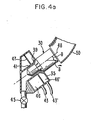
- the spectrometers described with reference to Figures 3 and 4 have a common pressure chamber supplying the jets 39 and 41. According to the invention however these spectrometers are modified as shown in Figure 4a in respect of Figure 4 so that the housing 35 is divided into two regions 46 and 46' supplied respectively by pressurized gas inlets 43 and 43'.
- the jets 39 are fed from the region 46' for rotating and levitating the rotor whereas the jets 41 are supplied through an independent pressurized gas inlet 43 to center the rotor, and to assist in rotating the rotor if the additional impelling surfaces are constructed on the surface of the cylindrical portion 33 as described above. Different pressures can therefore be maintained at jets 39 and 41.
Landscapes
- Physics & Mathematics (AREA)
- Condensed Matter Physics & Semiconductors (AREA)
- General Physics & Mathematics (AREA)
- Other Investigation Or Analysis Of Materials By Electrical Means (AREA)
- Magnetic Bearings And Hydrostatic Bearings (AREA)
- Sampling And Sample Adjustment (AREA)
Applications Claiming Priority (2)
| Application Number | Priority Date | Filing Date | Title |
|---|---|---|---|
| US06/042,821 US4275350A (en) | 1979-05-29 | 1979-05-29 | Sample spinning mechanism for NMR probes |
| US42821 | 1987-04-27 |
Related Parent Applications (2)
| Application Number | Title | Priority Date | Filing Date |
|---|---|---|---|
| EP80301683A Division EP0020085B1 (de) | 1979-05-29 | 1980-05-20 | Vorrichtung und Verfahren zum Drehen einer Probe für Sonden zur Untersuchung mittels kernmagnetischer Resonanz |
| EP80301683.1 Division | 1980-05-20 |
Publications (2)
| Publication Number | Publication Date |
|---|---|
| EP0089097A2 true EP0089097A2 (de) | 1983-09-21 |
| EP0089097A3 EP0089097A3 (de) | 1983-11-09 |
Family
ID=21923926
Family Applications (2)
| Application Number | Title | Priority Date | Filing Date |
|---|---|---|---|
| EP83200494A Withdrawn EP0089097A3 (de) | 1979-05-29 | 1980-05-20 | Vorrichtung zum Drehen einer Probe für Sonden der kernmagnetischen Resonanz |
| EP80301683A Expired EP0020085B1 (de) | 1979-05-29 | 1980-05-20 | Vorrichtung und Verfahren zum Drehen einer Probe für Sonden zur Untersuchung mittels kernmagnetischer Resonanz |
Family Applications After (1)
| Application Number | Title | Priority Date | Filing Date |
|---|---|---|---|
| EP80301683A Expired EP0020085B1 (de) | 1979-05-29 | 1980-05-20 | Vorrichtung und Verfahren zum Drehen einer Probe für Sonden zur Untersuchung mittels kernmagnetischer Resonanz |
Country Status (4)
| Country | Link |
|---|---|
| US (1) | US4275350A (de) |
| EP (2) | EP0089097A3 (de) |
| JP (1) | JPS55163447A (de) |
| DE (1) | DE3067674D1 (de) |
Cited By (2)
| Publication number | Priority date | Publication date | Assignee | Title |
|---|---|---|---|---|
| EP0249383A3 (en) * | 1986-06-03 | 1988-06-22 | Varian Associates, Inc. | High speed spinner for nmr spectrometer |
| EP3093679A1 (de) * | 2015-05-13 | 2016-11-16 | Bruker BioSpin GmbH | Mas-stator mit absaugvorrichtung |
Families Citing this family (28)
| Publication number | Priority date | Publication date | Assignee | Title |
|---|---|---|---|---|
| US4352066A (en) * | 1980-10-31 | 1982-09-28 | International Business Machines Corporation | Method for adjusting the magic angle in NMR experiments |
| US4446430A (en) * | 1981-08-31 | 1984-05-01 | Monsanto Company | Sample spinner for nuclear magnetic resonance spectrometer |
| US4456882A (en) * | 1982-01-04 | 1984-06-26 | University Of South Carolina | High speed cylindrical nuclear magnetic resonance (NMR) sample spinner |
| US4463328A (en) * | 1982-05-17 | 1984-07-31 | University Of South Carolina | Capacitively shortened coaxial resonators for nuclear magnetic resonance signal reception |
| US4511841A (en) * | 1982-06-17 | 1985-04-16 | Chemagnetics, Inc. | Method and apparatus for high speed magic angle spinning |
| US4510450A (en) * | 1982-09-28 | 1985-04-09 | The Medical College Of Wisconsin, Inc. | Apparatus and assay method for the quantitative determination of mineral content in bone |
| JPS61274245A (ja) * | 1985-04-08 | 1986-12-04 | バリアン・アソシエイツ・インコ−ポレイテツド | 自動化された交換器用のコ−デイングnmrサンプル |
| US4806868A (en) * | 1987-11-13 | 1989-02-21 | Varian Associates, Inc. | NMR spinner speed control |
| US4859949A (en) * | 1988-01-26 | 1989-08-22 | Siemens Aktiengesellschaft | Magnetic resonance spectroscopy apparatus |
| FR2628213B1 (fr) * | 1988-03-01 | 1990-06-22 | Sadis Bruker Spectrospin Sa | Sonde perfectionnee pour mesures spectrometriques de resonances magnetiques aux tres hautes temperatures |
| US4996483A (en) * | 1989-09-12 | 1991-02-26 | The United States Of America As Represented By The United States Department Of Energy | Spinning angle optical calibration apparatus |
| US5146166A (en) * | 1990-08-06 | 1992-09-08 | Chemagnetics, Inc. | Method and apparatus for enhancing sample analysis rate in magnetic resonance spectroscopy |
| US5202633A (en) * | 1990-11-01 | 1993-04-13 | Doty Scientific, Inc. | High temperature nmr sample spinner |
| US5260657A (en) * | 1992-03-26 | 1993-11-09 | Otsuka Electronics (U.S.A.) Inc. | Magnetic resonance spectroscopy sample spinning apparatus with mechanical bearing |
| US5289130A (en) * | 1992-07-31 | 1994-02-22 | Doty Scientific Inc. | NMR sample rotor cooling technique |
| WO1994028431A1 (en) * | 1993-05-21 | 1994-12-08 | The University Of Queensland | Nmr sample holder |
| EE00330U1 (et) * | 2002-05-30 | 2002-10-15 | Keemilise ja Bioloogilise F��sika Instituut | Tuuma magnetresonants-spektromeetri mõõtepea |
| US6812706B2 (en) * | 2003-03-12 | 2004-11-02 | Varian, Inc. | Axially-sealed NMR sample tube assemblies |
| US7170292B2 (en) * | 2004-10-20 | 2007-01-30 | Doty Scientific, Inc. | NMR MAS inflow bernoulli bearing |
| US7196521B2 (en) * | 2005-03-29 | 2007-03-27 | Doty Scientific, Inc. | NMR MAS electret spin rate detection |
| US7541807B2 (en) * | 2007-07-19 | 2009-06-02 | Varian, Inc. | Rotor drive apparatus and methods utilizing center-fed radial-outflow gas |
| CN106168589B (zh) * | 2013-03-05 | 2018-08-17 | 杨晓冬 | 一种生物医药用高分辨率核磁共振分析仪 |
| JP6622081B2 (ja) * | 2015-12-21 | 2019-12-18 | 日本電子株式会社 | 核磁気共鳴測定装置及び排ガス処理方法 |
| DE102017220709B4 (de) | 2017-11-20 | 2019-05-29 | Bruker Biospin Ag | MAS-NMR-Rotorsystem mit verbesserter Raumnutzung |
| WO2019108754A1 (en) * | 2017-12-01 | 2019-06-06 | Washington University | Systems, spherical rotors, stators, and methods of use |
| DE102020204379B3 (de) | 2020-04-03 | 2021-05-20 | Bruker Switzerland Ag | Magnetisch kompensierter NMR-Rotor und Verfahren zur Auslegung und Herstellung |
| US12253582B1 (en) * | 2022-04-11 | 2025-03-18 | University Of South Florida | Gas loader cell for solid-state NMR spinning or static rotors |
| DE102023202880B3 (de) | 2023-03-29 | 2024-07-18 | Bruker Biospin Gmbh | Verwendung Funktionsspezifischer Gase in einer MAS-Mikrogasturbine für die Festkörper NMR |
Family Cites Families (10)
| Publication number | Priority date | Publication date | Assignee | Title |
|---|---|---|---|---|
| US2960649A (en) * | 1954-06-18 | 1960-11-15 | Bloch Felix | Line narrowing gyromagnetic apparatus |
| US3038115A (en) * | 1957-02-11 | 1962-06-05 | Socony Mobil Oil Co Inc | Orientation of nuclear magnetic resonance samples |
| US3462677A (en) * | 1967-06-12 | 1969-08-19 | Varian Associates | Gyromagnetic resonance spectrometer having means for measuring the rate of sample rotation |
| US3588677A (en) * | 1968-05-15 | 1971-06-28 | Jury Lvovich Kleiman | Device for rotation of a thermostatted sample |
| GB1271262A (en) * | 1969-05-23 | 1972-04-19 | Cmw Lab Ltd | Turbines |
| US3681683A (en) * | 1970-09-14 | 1972-08-01 | Varian Associates | Gyromagnetic resonance spectrometer utilizing an improved sample spinning and ejecting structure |
| GB1480478A (en) * | 1973-05-21 | 1977-07-20 | Perkin Elmer Ltd | Spinning in a magnetic field |
| US4088944A (en) * | 1976-10-04 | 1978-05-09 | Varian Associates, Inc. | NMR Spectrometer employing self centering turbine |
| SU765724A1 (ru) * | 1977-06-03 | 1980-09-23 | Институт Кибернетики Ан Эстонской Сср | Датчик сигналов дерного магнитного резонанса |
| US4201941A (en) * | 1978-08-04 | 1980-05-06 | International Business Machines Corporation | Spinning apparatus for NMR spectrometers |
-
1979
- 1979-05-29 US US06/042,821 patent/US4275350A/en not_active Expired - Lifetime
-
1980
- 1980-05-20 EP EP83200494A patent/EP0089097A3/de not_active Withdrawn
- 1980-05-20 EP EP80301683A patent/EP0020085B1/de not_active Expired
- 1980-05-20 DE DE8080301683T patent/DE3067674D1/de not_active Expired
- 1980-05-29 JP JP7088080A patent/JPS55163447A/ja active Granted
Cited By (2)
| Publication number | Priority date | Publication date | Assignee | Title |
|---|---|---|---|---|
| EP0249383A3 (en) * | 1986-06-03 | 1988-06-22 | Varian Associates, Inc. | High speed spinner for nmr spectrometer |
| EP3093679A1 (de) * | 2015-05-13 | 2016-11-16 | Bruker BioSpin GmbH | Mas-stator mit absaugvorrichtung |
Also Published As
| Publication number | Publication date |
|---|---|
| EP0020085B1 (de) | 1984-05-02 |
| DE3067674D1 (en) | 1984-06-07 |
| EP0089097A3 (de) | 1983-11-09 |
| JPS6136613B2 (de) | 1986-08-19 |
| EP0020085A1 (de) | 1980-12-10 |
| US4275350A (en) | 1981-06-23 |
| JPS55163447A (en) | 1980-12-19 |
Similar Documents
| Publication | Publication Date | Title |
|---|---|---|
| EP0089097A2 (de) | Vorrichtung zum Drehen einer Probe für Sonden der kernmagnetischen Resonanz | |
| US4739270A (en) | High speed spinner for NMR spectrometer | |
| US5202633A (en) | High temperature nmr sample spinner | |
| US4088944A (en) | NMR Spectrometer employing self centering turbine | |
| US4254373A (en) | Sensor for generating nuclear magnetic resonance signals | |
| EP2327139B1 (de) | Rotorantriebsvorrichtung und -verfahren mit einem zentrumsgetriebenen radialausflussgas | |
| EP1457787B1 (de) | Axial-hermetisch abgeschlossene Probenbehälter für die NMR | |
| US5325059A (en) | DOR NMR sample spinner | |
| US3681683A (en) | Gyromagnetic resonance spectrometer utilizing an improved sample spinning and ejecting structure | |
| US3588677A (en) | Device for rotation of a thermostatted sample | |
| US10132881B2 (en) | MAS-stator with suctioning-off device | |
| JPS61502243A (ja) | 遠心分離機のためのロータ | |
| EP0009535B1 (de) | Rotoreinrichtung für kernmagnetische Resonanzspektrometer und Spektrometer, das diese Rotoreinrichtung umfasst | |
| JP2003505698A (ja) | 交換可能nmrフローチューブを有する貫流nmrプローブ | |
| US4046317A (en) | Air levitation device for an air driven centrifuge | |
| US9581663B2 (en) | NMR sample tube and NMR spectrometer | |
| US5816998A (en) | Centrifuge for test tubes and containers | |
| US10830845B2 (en) | MAS-NMR rotor system with improved space utilization | |
| US3038115A (en) | Orientation of nuclear magnetic resonance samples | |
| Balimann et al. | A magic-angle rotor for NMR using a forced gas bearing | |
| US11959837B2 (en) | Device for collecting particles or microorganisms | |
| US20050258834A1 (en) | Sample catcher for NMR apparatus and method utilizing thereof | |
| CN109814051B (zh) | 具有可更换的定子的魔角旋转核磁共振探头组件 | |
| RU2037142C1 (ru) | Устройство для измерения расхода жидкости или газа | |
| Lippmaa et al. | Magic Angle Spinning in High Resolution NMR Spectrometry of Solids |
Legal Events
| Date | Code | Title | Description |
|---|---|---|---|
| PUAI | Public reference made under article 153(3) epc to a published international application that has entered the european phase |
Free format text: ORIGINAL CODE: 0009012 |
|
| PUAL | Search report despatched |
Free format text: ORIGINAL CODE: 0009013 |
|
| 17P | Request for examination filed |
Effective date: 19830407 |
|
| AC | Divisional application: reference to earlier application |
Ref document number: 20085 Country of ref document: EP |
|
| AK | Designated contracting states |
Designated state(s): CH DE FR GB LI |
|
| AK | Designated contracting states |
Designated state(s): CH DE FR GB LI |
|
| RHK1 | Main classification (correction) |
Ipc: G01N 24/04 |
|
| STAA | Information on the status of an ep patent application or granted ep patent |
Free format text: STATUS: THE APPLICATION HAS BEEN WITHDRAWN |
|
| 18W | Application withdrawn |
Withdrawal date: 19831220 |
|
| RIN1 | Information on inventor provided before grant (corrected) |
Inventor name: HUBER, ULRICH Inventor name: HILL, HOWARD DAVID WILSON |