EP0089116A2 - Montage einer Wandplatte - Google Patents
Montage einer Wandplatte Download PDFInfo
- Publication number
- EP0089116A2 EP0089116A2 EP83300746A EP83300746A EP0089116A2 EP 0089116 A2 EP0089116 A2 EP 0089116A2 EP 83300746 A EP83300746 A EP 83300746A EP 83300746 A EP83300746 A EP 83300746A EP 0089116 A2 EP0089116 A2 EP 0089116A2
- Authority
- EP
- European Patent Office
- Prior art keywords
- panel
- secured
- wall panel
- plate
- frame
- Prior art date
- Legal status (The legal status is an assumption and is not a legal conclusion. Google has not performed a legal analysis and makes no representation as to the accuracy of the status listed.)
- Granted
Links
Images



Classifications
-
- E—FIXED CONSTRUCTIONS
- E04—BUILDING
- E04B—GENERAL BUILDING CONSTRUCTIONS; WALLS, e.g. PARTITIONS; ROOFS; FLOORS; CEILINGS; INSULATION OR OTHER PROTECTION OF BUILDINGS
- E04B2/00—Walls, e.g. partitions, for buildings; Wall construction with regard to insulation; Connections specially adapted to walls
- E04B2/74—Removable non-load-bearing partitions; Partitions with a free upper edge
- E04B2/7407—Removable non-load-bearing partitions; Partitions with a free upper edge assembled using frames with infill panels or coverings only; made-up of panels and a support structure incorporating posts
- E04B2/7416—Removable non-load-bearing partitions; Partitions with a free upper edge assembled using frames with infill panels or coverings only; made-up of panels and a support structure incorporating posts with free upper edge, e.g. for use as office space dividers
- E04B2/7422—Removable non-load-bearing partitions; Partitions with a free upper edge assembled using frames with infill panels or coverings only; made-up of panels and a support structure incorporating posts with free upper edge, e.g. for use as office space dividers with separate framed panels without intermediary support posts
- E04B2/7425—Details of connection of panels
Definitions
- This invention relates to panel assemblies of the kind including a support structure and panel skins mounted thereon.
- Modular wall panel assemblies are often used to divide a large room into a number of work areas separated by movable partitions which support both wall panels and desks.
- These office landscaping systems provide a relatively high concentration of work areas at relatively low cost, eliminating the need for expensive floor-to-ceiling partitions requiring permanent building modification.
- the work areas which are open at their tops, can be supplied with ambient light from a common source. Further, heating, cooling, and ventilation are facilitated because of the openness of the work areas.
- office landscaping systems comprise a plurality of wall panel sections, which are fastened together end-to-end.
- These panel sections comprise either 1) a relatively thick panel having mounting means on either end of the panel or 2) panel support frames to which are permanently secured panel skins. Consequently, the panel sections are relatively heavy, making installation and subsequent rearrangement relatively difficult. Further, the installation of electrical and telecommunications wiring in the panel sections is difficult because access may not be easily had to the panel section interiors. Examples of these systems may be seen in U.S. Patents 3,834,093, 3,831,330 and 3,802,146.
- systems comprising 3 modular support assembly, in which wiring is installed, and a plurality of panel skins suspended on the support assembly after the wiring is in place.
- An example of such a construction comprises a plurality of tubular nembers interconnected by brackets having fingers which extend through the member walls.
- this support assembly does not possess the required strength under high load conditions, for example when cabinets and desks are also supported on the support assembly.
- the panel skins are suspended on the support assembly by brackets which extend from the panel skins and rest on angled flanges on the support assembly. This panel skin mounting arrangement is unnecessarily complex and expensive.
- the panels are suspended on a support assembly by a plurality of hooks which extend from the panels over horizontal support members. Examples of these constructions may be seen in U.S. Patents 4,128,979 and 3,948,011 and the previously mentioned U.S. patents.
- these systems do not provide any means for laterally positioning the panel with respect to the support assembly because the clips are free to move laterally with respect to the horizontal members. Consequently, aligning the panels on the support assembly is relatively difficult.
- Yet another panel and frame assembly comprises a plurality of spring clips secured to the panel, which clips flex as the panels are installed and lockingly retain the panel on the frame.
- An example of this construction may be seen in U.S. Patent 3,286,412.
- this system does not precisely align the panels laterally on the support assembly.
- brackets are insufficiently strong under all applicable loads and/or excessively expensive to fabricate and/or excessively complicated to erect.
- a panel assembly comprises a support structure, a wall panel and means for attaching the panel to the support structure, characterised in that the attachment means comprises plate means on the support structure defining a plurality of vertical slots and a plurality of attachment studs extending from the panel, each of the studs comprising a shank slidingly received in one of the slots and a head coupled to the shank to retain the shank within the slot, the plate means having access means located above each slot permitting the head to pass from one side of the plate means to the other side thereof providing access to the slots for the shank whereby the wall panel is removably secured to the support means.
- a panel assembly comprises a panel support frame including first and second spaced uprights and first and second gussets including plate support means secured to and spaced outwardly from the first and second uprights, respectively,each of the gussets defining an upwardly opening slot; a support member including a third plate support means; a connector block defining first and second slot means for slidingly receiving the second and third plate support means, respectively; means for securing the second and third plate support means within the connector block to secure the frame and the support member together; a wall panel; and first and second mounting studs extending from the wall panel and ⁇ secured within the gussets, each of the studs including a shank slidably positioned within one of the slots and a head connected to the shank to prevent the shank from pulling out of the slot, whereby the wall panel is removably suspended on the frame.
- the panels may be mounted on the support assembly by positioning the panels against the support assembly with each mounting stud immediately above one of the upwardly opening slots and then lowering the panel such that each of the mounting studs is slidably secured within its associated slot. Therefore, the panel is precisely laterally positioned as it is suspended on the supporting assembly, eliminating alignment problems.
- a wall panel support structure comprises a first panel supporting frame means including a first secured portion; second panel supporting frame means including a second secured.portion; a connector block defining first and second slots in which the first and second secured portions, respectively, are slidingly received; a bearing member engaging the first and second secured portions and spaced from the connector block; and means for drawing the connector block and the bearing member toward one another to secure the secured portions therebetween to secure the first and second frame means together.
- the panel supporting structure includes a plurality of gussets, each of which defines one of the wall portions and a pair of the upwardly opening slots.
- the gussets serve both as an inter-frame connecting bracket.and as a support for the panel skins. This further reduces the cost and complexity of fabricating the modular assembly. Additionally, field installation is facilitated due to the relatively small number of parts involved.
- an L-shaped panel construction comprising interconnected support frames 10, inner and outer panels or panel skins 60, end caps 70, and corner cap 80.
- Support frames 10 shown in greater detail in Figure 2, each include a pair of vertical uprights 11 and 12, upper horizontal member 13, lower horizontal member 14, both extending between the uprights, and four gussets 20 each connecting a vertical member with a horizontal member. Gussets 20 on adjacent support frames 10 are interconnected using connector assemblies 40 to secure the frames together.
- .A corner post 15 is positioned at the corner of the L and secured to adjacent gussets 20 also using connector assemblies 40.
- Panels 60 are supported on either .side of the assembled frames 10 to provide planar partitions thereon.
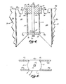
- each gusset 20 defines a pair of upwardly opening slots 28, which slidingly receive studs 61 extending from panels 60 (see Figures 6 and 7).
- the end caps 70 are supported at either end of the L shape between facing panels 60; and the corner cap 80 covers the exterior corner so .that a totally finished appearance is obtained.
- top caps (not shown), which are similar to -the.end caps 70 are installed along the upper edge of the assembly between facing wall panels 60 so that the support frames 10 are totally enclosed. The top caps are omitted from Figure 1 so that the support frames 10 may be more clearly shown.
- the modular components described may be used to construct work stations, such as 1) an office station having a desk and a cabinet supported above the desk or 2) a secretary's station including a desk and typewriter attachment. These types of work stations provide totally self-contained work areas which may be easily modified or relocated after initial assembly.
- each support frame comprises a pair of spaced, vertical uprights 11 and 12, horizontal top member 13 extending between the uprights, and lower horizontal support member 14 also extending between the uprights. All of members 11, 12, 13, and 14 are tubular; each of members 11, 12, and 13 is generally square in cross section, while lower member 14 is generally rectangular in cross section. Gussets 20 are used to interconnect vertical uprights 11 and 12 with horizontal members 13 and 14, respectively. As seen in Figure 7, each of the gussets 20 includes a pair of spaced plate sidewalls 21 and 22 between which members 11, 12, 13 and 14 are welded as required at each of the frame corners.
- the support members may be welded to one another within the gussets 20 for further rigidity.
- Each of the frames 10 is supported .on a base 16 ( Figure 2). Suffice it to say that the base 16 includes a foot 16a, support pieces 16b secured to the underside of the horiziontal member 14, and threaded members 16c extending between the foot 16a and the support pieces 16b to provide height adjustment between the horizontal member 14 and the foot 16a.
- Adjacent frames 10 are interconnected by placing gussets 20 from adjacent frames lOa and lOb adjacent one another and then interconnecting the gussets using connector assemblies 40.
- Each gusset 20 ( Figures 4 and 7) is generally U-shaped in cross section including a pair of parallel sidewalls 21 and 22 interconnected.by a generally perpendicular end wall 23.
- Sidewalls 21 and 22 each in turn comprises a pair of spaced, parallel securing portions 21a and 22a and a pair of spaced, parallel slot-defining portions 21b and 22b, respectively.
- the distance between the slot-defining portions 21b and 22b is somewhat less than the distance between the securing portions 21a and 22a.
- Support members 11, 12, 13 and 14 of support frames 10 interfit, and are secured, between the securing portions 21a and 22a (as shown in phantom in Figure 7).
- the securing portions 21a and 22a and the end wall 23 are generally rectangular, while slot-defining portions 21b and 22b are generally trapezoidal including a lower edge 24 which inclines upwardly from the securing portions 21a .and 21b to the end wall 23.
- Each of the end walls 23 includes an upper edge 25 and a lower edge 26.
- Slot-defining portions 21b and 22b define pockets or depressions 27, which extend inwardly toward one another and in turn define the slots 28, which receive the panel supporting studs 61 (see also Figure 6).
- Each of the slots 28 is generally U-shaped and opens upwardly.
- each slot 28 The upper edges 29a and 29b of each slot 28 are bevelled downwardly and inwardly toward the opposite slot 28 so that studs 61 are drawn toward the centre of the gusset 20 as the panels 60 are mounted on the frames 10. Additionally, the upper edges 29a and 29b of each slot 28 are bevelled downwardly toward one another to define an upwardly opening V to facilitate insertion of the mounting studs 61 into the slots.
- Each connector assembly 40 ( Figures 4 and 7) generally comprises a connector block 41, bearing plate 42, and bolt 43 extending therebetween.
- the block 41 has generally an H-shape comprising a central portion 46 and opposite, cross portions 47a and 47b.
- the central portion 46 defines a central vertical aperture 44; and the cross portions 47a and 47b define a pair of spaced, parallel slots 45a and 45b opening downwardly and extending through the block.
- the four corners 48 of the block 43 are each bevelled at approximately a 4S9 angle.
- the opening portions 49a and 49b of the slots 45a and 45b, respectively are bevelled or flare outwardly from one another to provide a funneling effect into the slots.
- the bearing plate 42 ( Figures 5 and 7) is a generally planar member defined by generally parallel sides 50 and arcuate sides 51 extending therebetween.
- the plate 42 defines a threaded aperture 55; and the radius of the arcuate sides 51 from the aperture 55 is equal to the distance between the aperture 55 and the sidewalls 21 and 22 in the connected assembly (see Figure 5).
- two camming lobes 52 are provided opposite one another at the junction of a straight side 50 with an arcuate side 51. Consequently, the plate 42 may be positioned between adjacent gussets 20 and rotated into position with the arcuate surfaces 51 travelling along sidewalls 21 and 22 until the camming lobes 52 abut sidewalls 22b to position the plate as shown in Figure 5.
- the bolt 43 is an elongated member having a hex head 53 at one end and a threaded portion 54 at its opposite end. In the assembled connector 40, the bolt 43 extends rotatably through the aperture 44 and is threadedly secured within the aperture 55 in the camming plate 52.
- Figures 3 and 4 illustrate the interconnection of two adjacent gussets 20 using the connector assembly 40.
- the end walls 23 of adjacent gussets 20 are positioned within respective slots 45a and 45b of the block 41.
- the bolt 43 is then inserted through : the aperture 44 in the block 41, and initially threaded into the aperture 55 in the plate 42.
- the connector assembly.40 may be preassembled with the bolt passing through both block 41 and plate 42. In either event, the bearing plate 42 is then rotated until it reaches the position shown in Figure 5 wherein .the sides 50 are generally parallel to the sidewalls 21. and 22 and wherein the camming lobes 52 abut the walls 22b.
- the panels 60 are generally planar members fabricated of glass fibre reinforced plastic (fibreglass). Panels 60 may optionally be covered with fabric (not shown) to give them a particular texture and colour desired in a particular application. Of course, the panels 60 may be fabricated of other materials, for example wood.
- a plurality of mounting studs 61 are mounted in the rear surface of the panels 60 to be positioned within the slots 28 when the panels 60 are mounted on the frames 10.
- Each of the studs 61 includes a shank or shaft portion 62 having a frustoconical head 63 integrally moulded thereon. The diameter of the shaft 62 is substantially the same as the width of the slot 28.
- the head 63 has an outer diameter greater than the diameter of the shaft 62 to retain the stud 61 within a slot 28.
- a threaded portion 64 extends from the shaft 62 and is threadedly secured within the panel 60.
- a hex head flange 65 extends radially from the shaft 62 adjacent the threaded portion 64 to facilitate installation of the studs 61 in the panel 60. Additionally, the studs 61 are secured within the panel 60 using adhesive or binder to strengthen the stud-to-panel connection.
- each bracket 66 is generally Z-shaped and comprises a securing flange 66a, a horizontal flange &6b, and a retention flange 66c.
- a threaded member 67 having an integral foot 68 thereon is threadedly carried within horizontal flange 66b, so that the foot rests on the horizontal member 13.
- the securing flange 66a is fastened to the panel 60 using screws 69.
- FIGs 2 and 9 illustrate a corner construction for the wall panel system, wherein the corner post 15 is used to join two frames 10 at right angles.
- the corner post 15 comprises a body portion 17, having a generally X-shaped cross section (see Figure 9), and sleeves or gussets 18 wrapped about and secured to the X-shaped body.
- the sleeves 18 are located at approximately the same height above the floor as the end walls 23 of the gussets 20; additionally, the sleeves 18 have approximately the same vertical extent as the end wall 23.
- Two frames lOb and 10c are joined at right angles by first connecting one frame to the corner post 15, interconnecting the sleeves 18 with the gussets 20 of the frame 10a using connecting assemblies 40.
- a second frame is then oriented generally at a right angle to the first frame 10a and secured to the corner post 15 by interconnecting sleeves 18 and gussets 20 of the frame 10b using connecting assemblies 40.
- the bevelled corners 48 on the blocks 41 permit a block 41 to be installed on the post 15 with the sleeve 18.positioned in the groove 45 and with the corners 48 engaging the legs of X-shaped body 17 (see Figure 9).
- up to four frames 10 may be connected to the corner post 15 all generally at right angles to each other.
- end caps 70 and the corner cap 80 are generally well known to those having ordinary skill in the art. Suffice it to say that caps 70 and 80 are suspended on frames 10 as necessary to totally enclose the support frames 10.
- the modular panel assembly described may be delivered to an installation site.as.a plurality of components. These modular components include frames 10 having gussets 20 mounted thereon, connector assemblies 40, panels 60, end caps 70, and corner caps 80.
- the support structure is first assembled by interconnecting a plurality of support frames 10 into the desired partitioning configuration. Adjacent frames 10 which are parallel to one another are connected by securing adjacent gussets from the two frames together using connector assemblies 40. Frames 10 which are oriented at right angles to one another are connected .to a common corner post 15 by interconnecting the sleeves 18 on the corner post with gussets 20 on each frame.
- each panel 60 is positioned against a frame 10 with each stud 61 positioned above one of the slots 28 defined by gussets 20 and with brackets 66 positioned above upper horizontal member 13.
- the panel is then lowered so that the studs .61 slidingly engage the slots 28, more particularly with the shaft 62 positioned within the slots and the heads 63 located within the gussets opposite the panel 60, until the feet 68 of adjusting screws 67 rest on the member 13.
- the heads 63 prevent the studs 61 from pulling out of the slots 28.
- the shafts 62 have substantially the same width as the slots:28, the studs 61 centre the panel 60 with respect to the frame 10 as the panel is lowered onto the frame.
- the upper edges 29 of each slot 28 guide the associated shaft 62 into the slot as the panel is lowered.
- the bevelled edges 29 force the head 63 inwardly into the gusset 20 drawing the panel 60 tightly against the frame 10.
- the height-adjusting screws 67 are then adjusted as necessary to vertically align the panel 60 on the frame 10.
- the end caps 70 and the corner caps 80 are installed to enclose the frames 10, giving the wall panel system a neat and finished appearance.
- a top cap (not shown) may be installed along the upper surface of the wall panel assembly to totally enclose the support structure.
Landscapes
- Engineering & Computer Science (AREA)
- Architecture (AREA)
- Physics & Mathematics (AREA)
- Electromagnetism (AREA)
- Civil Engineering (AREA)
- Structural Engineering (AREA)
- Body Structure For Vehicles (AREA)
- Load-Bearing And Curtain Walls (AREA)
- Finishing Walls (AREA)
- Cultivation Receptacles Or Flower-Pots, Or Pots For Seedlings (AREA)
Priority Applications (1)
| Application Number | Priority Date | Filing Date | Title |
|---|---|---|---|
| AT83300746T ATE20682T1 (de) | 1982-03-15 | 1983-02-15 | Montage einer wandplatte. |
Applications Claiming Priority (2)
| Application Number | Priority Date | Filing Date | Title |
|---|---|---|---|
| US358277 | 1982-03-15 | ||
| US06/358,277 US4443986A (en) | 1982-03-15 | 1982-03-15 | Panel construction system |
Publications (3)
| Publication Number | Publication Date |
|---|---|
| EP0089116A2 true EP0089116A2 (de) | 1983-09-21 |
| EP0089116A3 EP0089116A3 (en) | 1984-04-25 |
| EP0089116B1 EP0089116B1 (de) | 1986-07-09 |
Family
ID=23409018
Family Applications (1)
| Application Number | Title | Priority Date | Filing Date |
|---|---|---|---|
| EP83300746A Expired EP0089116B1 (de) | 1982-03-15 | 1983-02-15 | Montage einer Wandplatte |
Country Status (6)
| Country | Link |
|---|---|
| US (1) | US4443986A (de) |
| EP (1) | EP0089116B1 (de) |
| JP (1) | JPS58164851A (de) |
| AT (1) | ATE20682T1 (de) |
| CA (1) | CA1188867A (de) |
| DE (1) | DE3364401D1 (de) |
Cited By (1)
| Publication number | Priority date | Publication date | Assignee | Title |
|---|---|---|---|---|
| EP0459653A3 (en) * | 1990-05-31 | 1992-12-16 | Allsteel Inc. | Panel connector arrangement for office furniture demountable wall panel space divider systems |
Families Citing this family (15)
| Publication number | Priority date | Publication date | Assignee | Title |
|---|---|---|---|---|
| US4567698A (en) * | 1983-12-13 | 1986-02-04 | Knoll International, Inc. | Space divider system |
| US4625483A (en) * | 1985-06-03 | 1986-12-02 | Aspects, Inc. | Connector system for furniture panels |
| US4914873A (en) * | 1987-03-05 | 1990-04-10 | Herman Miller, Inc. | Work environment system |
| JPH0547114U (ja) * | 1991-11-30 | 1993-06-22 | 株式会社イトーキクレビオ | パネルの組立構造 |
| US5274970A (en) * | 1992-04-07 | 1994-01-04 | Roberts Raymond P | Freestanding partition system |
| JP2591046Y2 (ja) * | 1992-04-20 | 1999-02-24 | 株式会社イトーキクレビオ | 間仕切パネルの連結装置 |
| US5852904A (en) * | 1996-08-05 | 1998-12-29 | Haworth, Inc. | Panel arrangement |
| US6088980A (en) * | 1997-12-24 | 2000-07-18 | L & P Property Management Company | Space divider system |
| US6298619B1 (en) | 2000-03-02 | 2001-10-09 | William D. Davie | Modular building frame system |
| US6711871B2 (en) | 2000-05-03 | 2004-03-30 | Herman Miller, Inc. | Wall panel with off-module components |
| US6684929B2 (en) | 2002-02-15 | 2004-02-03 | Steelcase Development Corporation | Panel system |
| US7478504B2 (en) * | 2002-08-07 | 2009-01-20 | Plascore, Inc. | Wall system, mounting plate and insert |
| US7841142B2 (en) * | 2006-11-22 | 2010-11-30 | Steelcase Inc. | Stack-on panel assembly |
| US9206827B2 (en) | 2012-11-20 | 2015-12-08 | Avery Dennison Corporation | Wall mount organization system |
| GB2582728B (en) | 2018-12-27 | 2021-03-17 | Opeskina Olena | Modular system for transforming a vehicle parking space into a multifunctional environment |
Family Cites Families (49)
| Publication number | Priority date | Publication date | Assignee | Title |
|---|---|---|---|---|
| US27215A (en) * | 1860-02-21 | Island | ||
| US1748536A (en) * | 1927-09-12 | 1930-02-25 | Crouse Hinds Co | Electrical connecter |
| US1725120A (en) * | 1928-06-27 | 1929-08-20 | Malleable Iron Fittings Co | Means for supporting and bonding messenger cables and conduits for electrical conductors |
| US2010412A (en) * | 1932-01-29 | 1935-08-06 | Johns Manville | Wall structure |
| US1965597A (en) * | 1932-02-08 | 1934-07-10 | Mills Company | Interchangeable partition |
| US2033100A (en) * | 1932-10-20 | 1936-03-03 | Johns Manville | Structural assembly |
| US2092372A (en) * | 1933-04-29 | 1937-09-07 | Robert A Goeller | Connecter |
| US2137767A (en) * | 1937-12-17 | 1938-11-22 | David S Betcone | Building construction |
| US2388201A (en) * | 1943-06-08 | 1945-10-30 | Palnut Company | Clamp |
| US2763890A (en) * | 1953-12-09 | 1956-09-25 | William T Cox | Gate hinge |
| US2963131A (en) * | 1956-07-13 | 1960-12-06 | Corry Jamestown Mfg Corp | Post for free-standing partitions |
| US3072226A (en) * | 1958-06-18 | 1963-01-08 | Mills Company | Partition structure |
| US3034187A (en) * | 1959-08-14 | 1962-05-15 | Phillips Petroleum Co | Dual string tubing clamp |
| US3174590A (en) * | 1961-07-10 | 1965-03-23 | Armo Strut Corp | Structureal panel and building constructed therefrom |
| US3251163A (en) * | 1962-04-05 | 1966-05-17 | Lockheed Aircraft Corp | Clamp joint construction for prefabricated panels |
| US3245642A (en) * | 1963-08-28 | 1966-04-12 | Crown Controls Corp | Antenna support |
| US3286412A (en) * | 1964-02-13 | 1966-11-22 | Woodall Industries Inc | Panel and frame assembly |
| US3268946A (en) * | 1964-07-27 | 1966-08-30 | Anchor Post Prod | Gate hinge support clamp device |
| USRE27215E (en) | 1966-02-09 | 1971-11-02 | Space divider system | |
| US3425171A (en) * | 1966-02-09 | 1969-02-04 | Miller Herman Inc | Space divider system |
| US3430997A (en) * | 1967-05-17 | 1969-03-04 | Miller Herman Inc | Panel joint |
| US3537217A (en) * | 1968-02-08 | 1970-11-03 | Flangeklamp Corp | Wall structures |
| AU432925B2 (en) * | 1968-03-05 | 1973-02-22 | WILLIAM MALLINSON and SONS LIMITED | Improvements in or relating to partitions comprising demountable panels |
| US3517467A (en) * | 1968-06-17 | 1970-06-30 | Miller Herman Inc | Structural support system for shelving |
| US3592289A (en) * | 1968-09-06 | 1971-07-13 | Conwed Corp | Freestanding acoustical space divider |
| US3592288A (en) * | 1968-09-06 | 1971-07-13 | Conwed Corp | Acoustical panel for freestanding space divider |
| US3698147A (en) * | 1969-12-08 | 1972-10-17 | John Sikes | Structural member construction for building walls |
| US3638387A (en) * | 1970-03-10 | 1972-02-01 | Flangeklamp Corp | Method of erecting a wall panel supporting structure |
| US3830030A (en) * | 1972-03-07 | 1974-08-20 | T Yoshida | Device for detachably coupling furniture or building materials |
| US3831330A (en) * | 1972-03-14 | 1974-08-27 | Steelcase Inc | Panel system |
| US3834093A (en) * | 1972-03-14 | 1974-09-10 | Steelcase Inc | Panel jointure system |
| US3802146A (en) * | 1972-03-14 | 1974-04-09 | Steelcase Inc | Panel system |
| US3856244A (en) * | 1972-07-26 | 1974-12-24 | A Menshen | Clamping apparatus |
| US3948011A (en) * | 1972-09-29 | 1976-04-06 | Reginald Stanley Price | Partition system for a building |
| ES226939Y (es) * | 1974-07-29 | 1977-09-01 | Equipo de construccion de infraestructuras para un revesti- miento de pilotes. | |
| US3998018A (en) * | 1975-03-31 | 1976-12-21 | Kaiser Cement & Gypsum Corporation | Wall panel mounting system |
| USD246889S (en) | 1976-07-16 | 1978-01-10 | Conwed Corporation | Room divider connector or similar device |
| USD248823S (en) | 1976-07-16 | 1978-08-08 | Conwed Corporation | Room divider connector or similar device |
| US4100709A (en) * | 1976-09-30 | 1978-07-18 | Harter Corporation | Frame construction for a divider wall |
| US4204375A (en) * | 1976-09-30 | 1980-05-27 | Harter Corporation | Frame construction for a divider wall |
| SE7703556L (sv) * | 1977-03-28 | 1978-09-29 | Ohlson Kurt L | Anordning for fasthallande av tva parallellt eller atminstone vesentligen parallellt orienterade organ |
| CA1044870A (en) * | 1977-05-05 | 1978-12-26 | Reginald S. Price | Suspension assembly for partition panel |
| IT1079251B (it) * | 1977-06-24 | 1985-05-08 | Castelli Sas Anonima | Elementi modulari per la composizione di pareti armadi scrivante o altri articoli di arredamento di tipo scomponibile |
| US4123879A (en) * | 1977-06-27 | 1978-11-07 | American Seating Company | Panel wall systems with modular component build-up |
| US4232183A (en) * | 1977-08-29 | 1980-11-04 | Person Nelson H | Electrical connection system for panel structures |
| US4189884A (en) * | 1977-10-28 | 1980-02-26 | Irmo Pecoraro | Complex structure obtained from the utilization of particular clamps |
| US4219101A (en) * | 1978-06-12 | 1980-08-26 | Conwed Corporation | Acoustic space divider |
| US4214646A (en) * | 1978-06-19 | 1980-07-29 | Conwed Corporation | Space divider and acoustic panel |
| US4183485A (en) * | 1978-09-25 | 1980-01-15 | International Harvester Company | Mounting bracket for a cylindrical member |
-
1982
- 1982-03-15 US US06/358,277 patent/US4443986A/en not_active Expired - Fee Related
-
1983
- 1983-01-26 CA CA000420260A patent/CA1188867A/en not_active Expired
- 1983-02-15 AT AT83300746T patent/ATE20682T1/de active
- 1983-02-15 EP EP83300746A patent/EP0089116B1/de not_active Expired
- 1983-02-15 DE DE8383300746T patent/DE3364401D1/de not_active Expired
- 1983-03-09 JP JP58038895A patent/JPS58164851A/ja active Pending
Cited By (1)
| Publication number | Priority date | Publication date | Assignee | Title |
|---|---|---|---|---|
| EP0459653A3 (en) * | 1990-05-31 | 1992-12-16 | Allsteel Inc. | Panel connector arrangement for office furniture demountable wall panel space divider systems |
Also Published As
| Publication number | Publication date |
|---|---|
| ATE20682T1 (de) | 1986-07-15 |
| CA1188867A (en) | 1985-06-18 |
| EP0089116B1 (de) | 1986-07-09 |
| EP0089116A3 (en) | 1984-04-25 |
| DE3364401D1 (en) | 1986-08-14 |
| JPS58164851A (ja) | 1983-09-29 |
| US4443986A (en) | 1984-04-24 |
Similar Documents
| Publication | Publication Date | Title |
|---|---|---|
| EP0089116B1 (de) | Montage einer Wandplatte | |
| EP0200514B1 (de) | Trennwände für Büro | |
| US6009675A (en) | Knock-down portable partition system | |
| EP0247052B1 (de) | System von trennwandplatten | |
| EP0999314B1 (de) | Pfosten-Panele Verbindungsvorrichtung | |
| US6442909B2 (en) | Knock-down portable partition system | |
| US5159793A (en) | Wall system | |
| JP4050796B2 (ja) | 組立式可搬型間仕切りシステム | |
| US6052958A (en) | Wall panel system | |
| US4619486A (en) | Spine assembly | |
| US4120124A (en) | Movable wall assembly | |
| EP0006707A1 (de) | System zur Unterteilung eines Stockwerkraumes in mehrere Arbeitzonen | |
| US6513288B1 (en) | Window assembly for partitions | |
| CA2016604A1 (en) | Desk system | |
| JPH10507501A (ja) | モジュラー式オフィスファニチュアの間仕切り | |
| US6230459B1 (en) | Wall start for panel systems | |
| CA1046224A (en) | Panel joining and work surface support apparatus | |
| US6351917B1 (en) | Stacking connector for partitions | |
| NZ201180A (en) | Partition screen assembly-rigid linear coupling | |
| GB2246801A (en) | Space divider system, e.g. for offices | |
| GB2323027A (en) | Modular office furniture | |
| JPH08308648A (ja) | 組立式棚装置におけるキャビネット構造 | |
| CA1237266A (en) | Partition wall system | |
| WO2004033813A1 (en) | Reconfigurable frame system for interior use | |
| JPS5922203Y2 (ja) | 柵体の接続装置 |
Legal Events
| Date | Code | Title | Description |
|---|---|---|---|
| PUAI | Public reference made under article 153(3) epc to a published international application that has entered the european phase |
Free format text: ORIGINAL CODE: 0009012 |
|
| AK | Designated contracting states |
Designated state(s): AT BE CH DE FR GB IT LI LU NL SE |
|
| PUAL | Search report despatched |
Free format text: ORIGINAL CODE: 0009013 |
|
| AK | Designated contracting states |
Designated state(s): AT BE CH DE FR GB IT LI LU NL SE |
|
| 17P | Request for examination filed |
Effective date: 19841022 |
|
| ITF | It: translation for a ep patent filed | ||
| GRAA | (expected) grant |
Free format text: ORIGINAL CODE: 0009210 |
|
| AK | Designated contracting states |
Kind code of ref document: B1 Designated state(s): AT BE CH DE FR GB IT LI LU NL SE |
|
| PG25 | Lapsed in a contracting state [announced via postgrant information from national office to epo] |
Ref country code: AT Effective date: 19860709 |
|
| REF | Corresponds to: |
Ref document number: 20682 Country of ref document: AT Date of ref document: 19860715 Kind code of ref document: T |
|
| PG25 | Lapsed in a contracting state [announced via postgrant information from national office to epo] |
Ref country code: SE Effective date: 19860731 |
|
| REF | Corresponds to: |
Ref document number: 3364401 Country of ref document: DE Date of ref document: 19860814 |
|
| ET | Fr: translation filed | ||
| PG25 | Lapsed in a contracting state [announced via postgrant information from national office to epo] |
Ref country code: LU Free format text: LAPSE BECAUSE OF NON-PAYMENT OF DUE FEES Effective date: 19870228 Ref country code: LI Effective date: 19870228 Ref country code: CH Effective date: 19870228 |
|
| PLBE | No opposition filed within time limit |
Free format text: ORIGINAL CODE: 0009261 |
|
| STAA | Information on the status of an ep patent application or granted ep patent |
Free format text: STATUS: NO OPPOSITION FILED WITHIN TIME LIMIT |
|
| 26N | No opposition filed | ||
| BERE | Be: lapsed |
Owner name: STOW & DAVIS FURNITURE CY Effective date: 19870228 |
|
| PG25 | Lapsed in a contracting state [announced via postgrant information from national office to epo] |
Ref country code: NL Effective date: 19870901 |
|
| GBPC | Gb: european patent ceased through non-payment of renewal fee | ||
| NLV4 | Nl: lapsed or anulled due to non-payment of the annual fee | ||
| PG25 | Lapsed in a contracting state [announced via postgrant information from national office to epo] |
Ref country code: FR Free format text: LAPSE BECAUSE OF NON-PAYMENT OF DUE FEES Effective date: 19871030 |
|
| REG | Reference to a national code |
Ref country code: CH Ref legal event code: PL |
|
| PG25 | Lapsed in a contracting state [announced via postgrant information from national office to epo] |
Ref country code: DE Effective date: 19871103 |
|
| REG | Reference to a national code |
Ref country code: FR Ref legal event code: ST |
|
| PG25 | Lapsed in a contracting state [announced via postgrant information from national office to epo] |
Ref country code: GB Effective date: 19881122 |
|
| PG25 | Lapsed in a contracting state [announced via postgrant information from national office to epo] |
Ref country code: BE Effective date: 19890228 |