EP0089308A2 - Luftreifen - Google Patents
Luftreifen Download PDFInfo
- Publication number
- EP0089308A2 EP0089308A2 EP83630049A EP83630049A EP0089308A2 EP 0089308 A2 EP0089308 A2 EP 0089308A2 EP 83630049 A EP83630049 A EP 83630049A EP 83630049 A EP83630049 A EP 83630049A EP 0089308 A2 EP0089308 A2 EP 0089308A2
- Authority
- EP
- European Patent Office
- Prior art keywords
- tire
- tread
- axially
- grooves
- width
- Prior art date
- Legal status (The legal status is an assumption and is not a legal conclusion. Google has not performed a legal analysis and makes no representation as to the accuracy of the status listed.)
- Granted
Links
Images

Classifications
-
- B—PERFORMING OPERATIONS; TRANSPORTING
- B60—VEHICLES IN GENERAL
- B60C—VEHICLE TYRES; TYRE INFLATION; TYRE CHANGING; CONNECTING VALVES TO INFLATABLE ELASTIC BODIES IN GENERAL; DEVICES OR ARRANGEMENTS RELATED TO TYRES
- B60C11/00—Tyre tread bands; Tread patterns; Anti-skid inserts
- B60C11/03—Tread patterns
- B60C11/0306—Patterns comprising block rows or discontinuous ribs
-
- B—PERFORMING OPERATIONS; TRANSPORTING
- B60—VEHICLES IN GENERAL
- B60C—VEHICLE TYRES; TYRE INFLATION; TYRE CHANGING; CONNECTING VALVES TO INFLATABLE ELASTIC BODIES IN GENERAL; DEVICES OR ARRANGEMENTS RELATED TO TYRES
- B60C11/00—Tyre tread bands; Tread patterns; Anti-skid inserts
- B60C11/03—Tread patterns
- B60C11/11—Tread patterns in which the raised area of the pattern consists only of isolated elements, e.g. blocks
-
- B—PERFORMING OPERATIONS; TRANSPORTING
- B60—VEHICLES IN GENERAL
- B60C—VEHICLE TYRES; TYRE INFLATION; TYRE CHANGING; CONNECTING VALVES TO INFLATABLE ELASTIC BODIES IN GENERAL; DEVICES OR ARRANGEMENTS RELATED TO TYRES
- B60C11/00—Tyre tread bands; Tread patterns; Anti-skid inserts
- B60C11/03—Tread patterns
- B60C2011/0337—Tread patterns characterised by particular design features of the pattern
- B60C2011/0386—Continuous ribs
- B60C2011/0388—Continuous ribs provided at the equatorial plane
-
- Y—GENERAL TAGGING OF NEW TECHNOLOGICAL DEVELOPMENTS; GENERAL TAGGING OF CROSS-SECTIONAL TECHNOLOGIES SPANNING OVER SEVERAL SECTIONS OF THE IPC; TECHNICAL SUBJECTS COVERED BY FORMER USPC CROSS-REFERENCE ART COLLECTIONS [XRACs] AND DIGESTS
- Y10—TECHNICAL SUBJECTS COVERED BY FORMER USPC
- Y10S—TECHNICAL SUBJECTS COVERED BY FORMER USPC CROSS-REFERENCE ART COLLECTIONS [XRACs] AND DIGESTS
- Y10S152/00—Resilient tires and wheels
- Y10S152/902—Non-directional tread pattern having no circumferential rib and having blocks defined by circumferential grooves and transverse grooves
Definitions
- the present invention relates to pneumatic tires and more particularly to a novel tread configuration for tires of the radial type construction.
- the tread portion of a tire is generally defined by a plurality of grooves or depressions which form ground-engaging relief elements.
- the particular configuration of these relief elements has a significant effect upon the dry traction, wet traction, snow traction, noise level and rolling resistance of the tire.
- any particular tread pattern selected for any tire involves a compromise between these performance characteristics.
- the particular performance characteristics of the tire and the compromises between these performance characteristics is generally not known until the tire is actually made and tested.
- Applicants have'discovered a new tread configuration which permits the use of low rolling resistant compounds in the tread portion of the tire while maintaining acceptable levels of performance in dry traction, wet traction, snow traction and noise level.
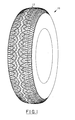
- a pneumatic tire 10 having a tread portion 12 made in accordance with the present invention.
- the tire 10 is of the radial type construction for use on passenger vehicles.
- a radial type construction shall be considered a tire having a carcass reinforcing ply structure which extends from bead to bead, the cords of the reinforcing ply structure being oriented at an angle in the range of 75° to 90° with respect to the mid-circumferential centerplane CP of the tire.
- the tread portion 12 is provided with a pair of axially opposed tread edges 14 which define the axially outer boundaries of the tread portion 12 which comes in contact with the ground-engaging surface upon which the tire is to be operated.
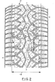
- a pair of generally zig-zag or sinuous grooves 16 which extend about the circumference of the tire are provided in the central portion of the tread portion 12, one on each side of the mid-circumferential centerplane CP of the tire.
- the grooves 16 are preferably spaced equidistant from the mid-circumferential centerplane of the tire and form a generally zig-zag or sinuous central rib 20 which extends about the circumference of the tire 10.
- Each central zig-zag groove 16 comprises a plurality of alternating axially inner peaks 18 and axially outer peaks 19 with respect to the mid-circumferential centerplane CP of the tire.
- Each groove 16 has an amplitude A, as measured from the center line of the groove, in the range of 5% to 15% of the tread width TW, preferably, as illustrated, of about 10%.
- the tread width TW is the maximum axial distance perpendicular to the mid-circumferential centerplane CP of the tire between tread edges 14 as measured from the footprint of the tire inflated to design inflation pressure and at rated load.
- the cross-sectional width Wl of rib 20 may range from about 5% to 15% of the tread width TW.
- the cross-sectional width Wl is approximately 10%.
- the cross-sectional width Wl is measured perpendicular to the overall direction of the rib 20.
- Rib 20 and grooves 16 each have a repeating longitudinal frequency Fl which ranges from about 40% to 60% of the tread width TW, preferably of about 50%.
- the repeating longitudinal frequency Fl is the circumferential distance in which the zig-zag path or rib 20 or grooves 16 goes through one complete cycle as is illustrated in figure 2.
- each zig-zag groove 16 Disposed axially outward of each zig-zag groove 16 with respect to the mid-circumferential centerplane CP of the tire 10 is an intermediate generally zig-zag or sinuous groove 22 having a plurality of axially inner peaks 23 which circumferentially alternate with axially outer peaks 24.
- Intermediate zig-zag groove 22 has a repeating longitudinal frequency F2 which is equal to approximately twice that of the central zig-zag groove 16, that is, for every single repeating frequency Fl of central zig-zag groove 16, zig-zag groove 22 has two repeating zig-zag cycles.
- Intermediate zig-zag grooves 22 are each disposed such that every other circumferentially adjacent inner peak 23 coincides with circumferentially adjacent axially outer peak 19 of zig-zag grooves 16.
- the amplitude C of each intermediate groove, as measured from the center line of the groove, may range from about 10% to 25% of the tread width, preferably of about 15%.
- the tread portion 12 is further provided with a plurality of substantially axially extending grooves 26 which extend from each axially outer peak 24 of each intermediate groove 16 to the closest respective tread edge 14.
- each groove 26 comprises a single straight groove which lies at an angle of no less than about 75° with respect to the mid-circumferential centerplane CP.
- the grooves 26 lie at an angle of approximately 85° with respect to the mid-circumferential centerplane CP.
- the grooves 16, 22 and 26 each have a width such that when in the footprint of the tire the grooves do not close up at the surface of the tread portion 12.
- Grooves 16 and intermediate grooves 22 combine to form a plurality of relief elements 25 spaced about the circumference of the tire 10 such that a single relief element 25 is disposed between circumferentially adjacent axially outer peaks 19 of grooves 16.
- Each intermediate relief element 25 has a generally outer configuration substantially that of a crescent shape with the convex side facing the rib 20 and the concave side facing the closest respective tread edge 14.
- the concave side of each intermediate relief element 25 has a generally V or Ushape configuration.
- each shoulder relief element 27 which extends from the concave side of each intermediate relief element axially outward towards the closest respective tread edge 14.
- the axially inner end 28 of each shoulder relief element 27 having a generally V or U shape configuration.
- Each shoulder element 27 is preferably provided with at least one narrow groove 31 which extends from the tread edge axially inward terminating within the element, preferably not extending more than 50% of the axial width W2 of the element 27.
- Rib 20 intermediate relief element 25 and shoulder relief element 27 are each provided with at least one narrow cut or blade 30 which extends from the periphery of the element axially inward terminating within the element.
- Each blade 30 comprises a first segment oriented at an angle of approximately 45° with respect to the mid-circumferential centerplane of the tire and a second segment oriented at an angle of approximately 90° to the mid-circumferential centerplane of the tire.
- these blades may be entirely omitted if desired.
- a blade shall be considered a narrow groove which when in the footprint of the tire closes up at the tread surface.
- the present invention is not so limited. If desired, the central portion of the tire between grooves 16 may be provided with a plurality of independent projections. Referring to figure 3, there is illustrated a modified. form of the present invention wherein the central portion of the tire is provided with a plurality of independent elements 33.
- the repeating design cycle may be varied about the circumference of the tire (also generally known as pitching of the tread pattern).
Landscapes
- Engineering & Computer Science (AREA)
- Mechanical Engineering (AREA)
- Tires In General (AREA)
Applications Claiming Priority (2)
| Application Number | Priority Date | Filing Date | Title |
|---|---|---|---|
| US06/358,945 US4424845A (en) | 1982-03-17 | 1982-03-17 | Pneumatic tire tread |
| US358945 | 1982-03-17 |
Publications (3)
| Publication Number | Publication Date |
|---|---|
| EP0089308A2 true EP0089308A2 (de) | 1983-09-21 |
| EP0089308A3 EP0089308A3 (en) | 1984-08-22 |
| EP0089308B1 EP0089308B1 (de) | 1987-08-12 |
Family
ID=23411676
Family Applications (1)
| Application Number | Title | Priority Date | Filing Date |
|---|---|---|---|
| EP83630049A Expired EP0089308B1 (de) | 1982-03-17 | 1983-03-15 | Luftreifen |
Country Status (7)
| Country | Link |
|---|---|
| US (1) | US4424845A (de) |
| EP (1) | EP0089308B1 (de) |
| JP (1) | JPS58167205A (de) |
| AU (1) | AU549111B2 (de) |
| BR (1) | BR8301029A (de) |
| CA (1) | CA1193954A (de) |
| DE (1) | DE3372950D1 (de) |
Cited By (7)
| Publication number | Priority date | Publication date | Assignee | Title |
|---|---|---|---|---|
| EP0173783A1 (de) * | 1984-08-28 | 1986-03-12 | The Goodyear Tire & Rubber Company | Luftreifen |
| GB2192842A (en) * | 1986-06-13 | 1988-01-27 | Bridgestone Corp | Pneumatic tire |
| EP0239521A3 (en) * | 1986-03-18 | 1988-08-10 | The Goodyear Tire & Rubber Company | High performance all-season tire |
| DE3912358A1 (de) * | 1988-05-04 | 1989-11-16 | Semperit Gmbh | Laufflaechenprofil fuer einen fahrzeugluftreifen |
| DE4239475A1 (de) * | 1992-11-25 | 1994-05-26 | Continental Ag | Fahrzeugreifen mit Laufflächenprofil |
| EP0688685A3 (de) * | 1994-06-23 | 1996-04-17 | Bridgestone Corp | Luftreifen |
| EP2202098A4 (de) * | 2007-09-18 | 2013-07-24 | Bridgestone Corp | Luftreifen |
Families Citing this family (18)
| Publication number | Priority date | Publication date | Assignee | Title |
|---|---|---|---|---|
| USD283214S (en) | 1984-06-13 | 1986-04-01 | The Firestone Tire & Rubber Company | Tire |
| JPS61235206A (ja) * | 1985-04-12 | 1986-10-20 | Sumitomo Rubber Ind Ltd | ハイパフオ−マンスタイヤ |
| DE3662362D1 (en) * | 1985-10-24 | 1989-04-20 | Ecia Equip Composants Ind Auto | Position-adjusting device for a belt anchor, in particular for a motor vehicle seat belt |
| IT1222420B (it) * | 1986-08-05 | 1990-09-05 | Uniroyal Englebert Gmbh | Scolpitura di battistrada di pneumatici per autoveicoli |
| JPH0780405B2 (ja) * | 1987-04-14 | 1995-08-30 | マツダ株式会社 | 自動車のリヤサスペンシヨン構造 |
| US4936363A (en) * | 1988-08-15 | 1990-06-26 | The Goodyear Tire & Rubber Company | Tread for a pneumatic tire with circumferential slot to prevent the spread of river wear |
| USD388035S (en) * | 1995-11-07 | 1997-12-23 | The Goodyear Tire & Rubber Company | Tire tread |
| JP2934405B2 (ja) * | 1996-01-30 | 1999-08-16 | 住友ゴム工業株式会社 | 空気入りタイヤ |
| USD403275S (en) | 1997-12-03 | 1998-12-29 | The Goodyear Tire & Rubber Company | Tire tread |
| USD402933S (en) | 1997-12-09 | 1998-12-22 | The Goodyear Tire & Rubber Company | Tire tread |
| USD413088S (en) | 1998-09-18 | 1999-08-24 | The Goodyear Tire & Rubber Company | Tire tread |
| USD444743S1 (en) | 2000-06-19 | 2001-07-10 | The Goodyear Tire & Rubber Company | Tire tread |
| USD537406S1 (en) * | 2006-02-02 | 2007-02-27 | Michelin Recherche Et Technique S.A. | Tire tread |
| USD549158S1 (en) * | 2006-04-19 | 2007-08-21 | The Goodyear Tire & Rubber Company | Tire tread |
| JP6118307B2 (ja) * | 2014-12-17 | 2017-04-19 | 住友ゴム工業株式会社 | 空気入りタイヤ |
| RU2703006C2 (ru) * | 2015-04-03 | 2019-10-15 | Сумитомо Раббер Индастриз, Лтд. | Пневматическая шина |
| JP6378798B2 (ja) * | 2017-03-22 | 2018-08-22 | 住友ゴム工業株式会社 | 空気入りタイヤ |
| JP7225870B2 (ja) * | 2019-02-06 | 2023-02-21 | 住友ゴム工業株式会社 | タイヤ |
Family Cites Families (11)
| Publication number | Priority date | Publication date | Assignee | Title |
|---|---|---|---|---|
| CH270731A (it) * | 1949-03-10 | 1950-09-15 | Az Ceat Gomma Soc Per | Battistrada per coperture pneumatiche di autoveicoli. |
| DE1505140A1 (de) * | 1963-01-16 | 1969-05-22 | Phoenix Gummiwerke Ag | Laufflaechenprofilierung fuer Lkw-Reifen |
| DE1248523B (de) | 1964-02-22 | 1967-08-24 | Einfalt Geb | Spielzeug mit einer geneigt verlaufenden Fahrbahn sowie einem Spielfahrzeuge anhebenden Aufzug |
| US3608602A (en) * | 1968-12-03 | 1971-09-28 | Uniroyal Inc | Stone rejecting tire tread and mold insert therefor |
| JPS497760B1 (de) * | 1969-01-29 | 1974-02-22 | ||
| DE2710825A1 (de) | 1977-03-11 | 1978-09-14 | Uniroyal Ag | Laufflaechenprofil fuer fahrzeugluftreifen |
| JPS54159901A (en) * | 1978-06-09 | 1979-12-18 | Bridgestone Corp | Pneumatic tire for large motorcycle suitable for high speed driving |
| JPS55114605A (en) * | 1979-02-28 | 1980-09-04 | Yokohama Rubber Co Ltd:The | All-weather tire |
| US4282915A (en) * | 1980-02-21 | 1981-08-11 | The Goodyear Tire & Rubber Company | Pneumatic tire |
| FR2483332A1 (fr) * | 1980-05-28 | 1981-12-04 | Kleber Colombes | Pneumatique pour vehicule de tourisme |
| JPS579968A (en) * | 1980-06-19 | 1982-01-19 | Nippon Kokan Kk | Floating method of cylindrical tank roof |
-
1982
- 1982-03-17 US US06/358,945 patent/US4424845A/en not_active Expired - Fee Related
-
1983
- 1983-03-03 BR BR8301029A patent/BR8301029A/pt not_active IP Right Cessation
- 1983-03-09 CA CA000423224A patent/CA1193954A/en not_active Expired
- 1983-03-10 AU AU12348/83A patent/AU549111B2/en not_active Ceased
- 1983-03-11 JP JP58039330A patent/JPS58167205A/ja active Pending
- 1983-03-15 EP EP83630049A patent/EP0089308B1/de not_active Expired
- 1983-03-15 DE DE8383630049T patent/DE3372950D1/de not_active Expired
Cited By (9)
| Publication number | Priority date | Publication date | Assignee | Title |
|---|---|---|---|---|
| EP0173783A1 (de) * | 1984-08-28 | 1986-03-12 | The Goodyear Tire & Rubber Company | Luftreifen |
| EP0239521A3 (en) * | 1986-03-18 | 1988-08-10 | The Goodyear Tire & Rubber Company | High performance all-season tire |
| GB2192842A (en) * | 1986-06-13 | 1988-01-27 | Bridgestone Corp | Pneumatic tire |
| GB2192842B (en) * | 1986-06-13 | 1991-01-30 | Bridgestone Corp | Pneumatic tire |
| US5152854A (en) * | 1986-06-13 | 1992-10-06 | Bridgestone Corporation | Pneumatic tire having directional tread |
| DE3912358A1 (de) * | 1988-05-04 | 1989-11-16 | Semperit Gmbh | Laufflaechenprofil fuer einen fahrzeugluftreifen |
| DE4239475A1 (de) * | 1992-11-25 | 1994-05-26 | Continental Ag | Fahrzeugreifen mit Laufflächenprofil |
| EP0688685A3 (de) * | 1994-06-23 | 1996-04-17 | Bridgestone Corp | Luftreifen |
| EP2202098A4 (de) * | 2007-09-18 | 2013-07-24 | Bridgestone Corp | Luftreifen |
Also Published As
| Publication number | Publication date |
|---|---|
| CA1193954A (en) | 1985-09-24 |
| AU549111B2 (en) | 1986-01-16 |
| DE3372950D1 (en) | 1987-09-17 |
| EP0089308A3 (en) | 1984-08-22 |
| US4424845A (en) | 1984-01-10 |
| JPS58167205A (ja) | 1983-10-03 |
| BR8301029A (pt) | 1983-11-22 |
| AU1234883A (en) | 1983-09-22 |
| EP0089308B1 (de) | 1987-08-12 |
Similar Documents
| Publication | Publication Date | Title |
|---|---|---|
| US4424845A (en) | Pneumatic tire tread | |
| US4424843A (en) | Pneumatic tire tread | |
| EP0089306B1 (de) | Reifenlauffläche | |
| US4574856A (en) | Tread for a pneumatic tire | |
| US4702292A (en) | High performance all-season tire tread | |
| EP1363790B1 (de) | Reifenlauffläche für kraftfahrzeuge, insbesondere für wintereinsatz | |
| EP0455925B1 (de) | Ganz-Jahr-Lauffläche | |
| US4545415A (en) | Pneumatic tire tread | |
| US4462446A (en) | Pneumatic tire tread | |
| EP0173783B1 (de) | Luftreifen | |
| US4546808A (en) | Pneumatic tire | |
| US6446689B1 (en) | Pneumatic tire having 80 to 105 pitches | |
| US4351381A (en) | Tread for pneumatic tire | |
| US4397344A (en) | Tread for heavy-duty radial tires | |
| CA1122892A (en) | Pneumatic truck tire | |
| EP2923859A2 (de) | Luftreifen | |
| US4779656A (en) | Pneumatic tire | |
| EP0473860A1 (de) | Laufstreifen für Luftreifen für LKW | |
| US4641695A (en) | Tread for a pneumatic tire | |
| US4609022A (en) | Pneumatic tire | |
| US6439285B1 (en) | Pneumatic tire having 98 pitches | |
| CA1143265A (en) | Tire tread with independent projections | |
| US6435237B1 (en) | Pneumatic tire having generally rounded footprint shape | |
| EP0119947B1 (de) | Luftreifen | |
| CA1234342A (en) | Tread for a pneumatic tire |
Legal Events
| Date | Code | Title | Description |
|---|---|---|---|
| PUAI | Public reference made under article 153(3) epc to a published international application that has entered the european phase |
Free format text: ORIGINAL CODE: 0009012 |
|
| 17P | Request for examination filed |
Effective date: 19830325 |
|
| AK | Designated contracting states |
Designated state(s): DE FR GB IT LU |
|
| PUAL | Search report despatched |
Free format text: ORIGINAL CODE: 0009013 |
|
| AK | Designated contracting states |
Designated state(s): DE FR GB IT LU |
|
| GRAA | (expected) grant |
Free format text: ORIGINAL CODE: 0009210 |
|
| AK | Designated contracting states |
Kind code of ref document: B1 Designated state(s): DE FR GB IT LU |
|
| REF | Corresponds to: |
Ref document number: 3372950 Country of ref document: DE Date of ref document: 19870917 |
|
| ET | Fr: translation filed | ||
| ITF | It: translation for a ep patent filed | ||
| PLBE | No opposition filed within time limit |
Free format text: ORIGINAL CODE: 0009261 |
|
| STAA | Information on the status of an ep patent application or granted ep patent |
Free format text: STATUS: NO OPPOSITION FILED WITHIN TIME LIMIT |
|
| 26N | No opposition filed | ||
| REG | Reference to a national code |
Ref country code: FR Ref legal event code: CL |
|
| ITTA | It: last paid annual fee | ||
| EPTA | Lu: last paid annual fee | ||
| PGFP | Annual fee paid to national office [announced via postgrant information from national office to epo] |
Ref country code: LU Payment date: 20000210 Year of fee payment: 18 |
|
| PGFP | Annual fee paid to national office [announced via postgrant information from national office to epo] |
Ref country code: GB Payment date: 20010202 Year of fee payment: 19 |
|
| PGFP | Annual fee paid to national office [announced via postgrant information from national office to epo] |
Ref country code: FR Payment date: 20010301 Year of fee payment: 19 |
|
| PG25 | Lapsed in a contracting state [announced via postgrant information from national office to epo] |
Ref country code: LU Free format text: LAPSE BECAUSE OF NON-PAYMENT OF DUE FEES Effective date: 20010315 |
|
| PGFP | Annual fee paid to national office [announced via postgrant information from national office to epo] |
Ref country code: DE Payment date: 20010330 Year of fee payment: 19 |
|
| REG | Reference to a national code |
Ref country code: GB Ref legal event code: IF02 |
|
| PG25 | Lapsed in a contracting state [announced via postgrant information from national office to epo] |
Ref country code: GB Free format text: LAPSE BECAUSE OF NON-PAYMENT OF DUE FEES Effective date: 20020315 |
|
| PG25 | Lapsed in a contracting state [announced via postgrant information from national office to epo] |
Ref country code: DE Free format text: LAPSE BECAUSE OF NON-PAYMENT OF DUE FEES Effective date: 20021001 |
|
| GBPC | Gb: european patent ceased through non-payment of renewal fee |
Effective date: 20020315 |
|
| PG25 | Lapsed in a contracting state [announced via postgrant information from national office to epo] |
Ref country code: FR Free format text: LAPSE BECAUSE OF NON-PAYMENT OF DUE FEES Effective date: 20021129 |
|
| REG | Reference to a national code |
Ref country code: FR Ref legal event code: ST |