EP0089421A1 - Armband insbesondere Uhrarmband und seine Zusammenfügung - Google Patents
Armband insbesondere Uhrarmband und seine Zusammenfügung Download PDFInfo
- Publication number
- EP0089421A1 EP0089421A1 EP82200359A EP82200359A EP0089421A1 EP 0089421 A1 EP0089421 A1 EP 0089421A1 EP 82200359 A EP82200359 A EP 82200359A EP 82200359 A EP82200359 A EP 82200359A EP 0089421 A1 EP0089421 A1 EP 0089421A1
- Authority
- EP
- European Patent Office
- Prior art keywords
- elements
- flat
- cylindrical
- bracelet
- orifice
- Prior art date
- Legal status (The legal status is an assumption and is not a legal conclusion. Google has not performed a legal analysis and makes no representation as to the accuracy of the status listed.)
- Withdrawn
Links
- 238000000034 method Methods 0.000 title claims description 6
- 230000000295 complement effect Effects 0.000 abstract 1
- 238000004519 manufacturing process Methods 0.000 description 3
- 229910000831 Steel Inorganic materials 0.000 description 2
- 230000000694 effects Effects 0.000 description 2
- 210000000056 organ Anatomy 0.000 description 2
- 238000000926 separation method Methods 0.000 description 2
- 239000010959 steel Substances 0.000 description 2
- 230000006835 compression Effects 0.000 description 1
- 238000007906 compression Methods 0.000 description 1
- 238000005553 drilling Methods 0.000 description 1
- 238000003780 insertion Methods 0.000 description 1
- 230000037431 insertion Effects 0.000 description 1
- 239000000463 material Substances 0.000 description 1
- 230000000750 progressive effect Effects 0.000 description 1
- 239000007787 solid Substances 0.000 description 1
Images
Classifications
-
- A—HUMAN NECESSITIES
- A44—HABERDASHERY; JEWELLERY
- A44C—PERSONAL ADORNMENTS, e.g. JEWELLERY; COINS
- A44C5/00—Bracelets; Wrist-watch straps; Fastenings for bracelets or wrist-watch straps
- A44C5/02—Link constructions
- A44C5/10—Link constructions not extensible
- A44C5/107—Link constructions not extensible with links made of more than two elements including connecting elements
Definitions
- the present invention relates to a bracelet, in particular for a watch, consisting of a chain of elongated flat elements, provided on their lateral faces with a groove of circular section, two adjacent flat elements being interconnected by a connecting element provided laterally of two parallel cylindrical ribs, intended to engage, by sliding, in the circular grooves of two adjacent flat elements.
- Such bracelets are already known, for example, from Swiss Patent No.602 034.
- the connecting elements are shorter than the flat links and the means of fixing between the flat links and the connecting elements are constituted by plugs placed at the ends of the circular grooves after the connection elements have been fitted.
- connection means are known between the links of a bracelet by steel balls.
- An example of this type of bracelet is described in patent CH No. 614 360 in which the elements of the bracelet are profiled so as to interpenetrate longitudinally with a lateral clearance allowing the insertion of the steel balls between the lateral faces in look. Compression of the links in the transverse axis of the bracelet makes it possible to trap the balls between said opposite faces thanks to the deformation of the elements.
- the present invention aims to produce an improved bracelet, of the type described above, and in which the connecting means between the various elements are mounted quickly and easily and also make it possible to provide removable elements for adjusting the length of the bracelet.
- the bracelet according to the invention is characterized in that the fixing between the flat elements and the connecting elements is ensured by a spherical connecting member surmounted by a flat cylindrical head, said connecting member being introduced in a cylindrical orifice perpendicular to the plane of the elements and which intersects the circular groove of the flat element and the cylindrical rib of the element liaison ment.
- the invention further relates to the method of mounting such a bracelet, characterized in that a chain of flat elements is assembled by sliding connecting elements between two adjacent flat elements, which are drilled at minus two cylindrical orifices in each flat element, perpendicular to its plane, so that each orifice intersects both the circular groove of the flat element and the cylindrical rib of the connecting element, which the organ is introduced of connection in said orifice and that a desired number of elements of the chain are separated to form a bracelet.
- this bracelet is greatly facilitated since it is both the flat elements and the pre-assembled connecting elements which are drilled simultaneously in a single operation to form the orifice into which will then be introduced either by hunting, or by screwing, the connecting member. It is thus certain that the elements are well arranged relatively to each other and the introduction of the connecting member can be carried out without difficulty.
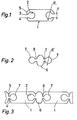
- the bracelet consists of a chain of flat elements 1 (fig. 1), cut from a profile, these flat elements 1 being elongated, solid, and provided on their lateral faces with a groove 2 of circular section. which opens onto the lateral face by a slot 3 with a width f less than the diameter d of the groove.
- the lower edge 4 of the slot 3 is slightly set back from the upper edge 5 and is further rounded, so as to form a clearance allowing the articulation to be able to operate towards the interior of the bracelet.
- Two adjacent flat elements 1 are interconnected by a connecting element 6 (fig.2) laterally provided with two parallel cylindrical ribs 7, the diameter of which is approximately equal to, or slightly less than the diameter of the groove 2.
- These cylindrical ribs 7 are connected to the body of the element 6 by a rectangular rib 8 whose thickness f 'is approximately equal to or slightly less than the width f of the slot 3.
- the flat elements 1 are therefore assembled by sliding connecting elements between two adjacent elements 6.
- the cylindrical ribs 7 slide into the circular grooves 2 of two adjacent flat elements while the rectangular ribs 8 s' engage in slots 3; the upper edges 5 of the slot 3 are applied against the rectangular rib 8 while the rounded lower edges 4 leave a clearance which allows the joint to function.
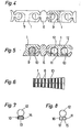
- the flat elements and the connecting elements are drilled simultaneously to form orifices 9, perpendicular to the plane of the elements and which intersect the circular groove 2 of the flat element 1 and therefore the cylindrical rib 7 of the connecting element 6.
- orifices 9 are provided per element, preferably located on the center line, but two pairs of orifices could also be provided equidistant from this center line.
- connecting members 10, 11 comprising a spherical part 12 surmounted by a flat cylindrical head 13, 15 are introduced into the orifices thus formed.
- a connecting element 10 (fig. 7) is used, the cylindrical head 13 of which has the knurled edge 14, while in the event of a possible dismantling of the elements with a view to adjusting the length of the bracelet, a connecting element 11 (fig.8) is used, the head 15 of which is provided with a thread 16 and a slot 17 for the passage of a screwdriver.
- the non-removable connecting members 10 are introduced into the cylindrical orifices 9 by force removal while the removable connecting elements 11 are simply screwed into orifices 9 previously tapped.
- the dimensions of the connecting member 9 or 10 are such that the diameter of the spherical part 12 is approximately equal to the diameter of the cylindrical rib 7 and the depth of the orifice 9 is such that the spherical part 12 reaches approximately the same level than the bottom of the cylindrical groove 2.
- this connecting member 10,11 does not cause any discomfort during operation of the joint, the spherical part 12 of the connecting member 10,11 does not interfere with the rotation of the cylindrical rib 7 in the groove 2 of the same profile.
- the height of the connecting member 10, 11 is further such that the flat cylindrical head is flush with the surface of the flat element 1.
- a long chain of flat elements 1 and of connection 2 is assembled together, their drilling is carried out and the connecting members 10 are driven into the orifices 9 before proceeding with the separation of a desired number of elements of the chain to constitute a strand of bracelet.
- certain unassembled elements are reserved to allow this separation, as well as the introduction of removable connecting members 11.
- the flat elements 1 and of connection 6 are of the same length.
- the flat elements 1 and of connection have their milled ends so that a connection element has the same length as two flat elements 1 which are adjacent to it.
- the end faces of the connecting elements 6 are flush with the end faces of the two adjacent flat elements.
- the members the link 10, 11 are provided to be mounted. on the underside of the bracelet. It is obvious that they could also be mounted from the upper face, and made of a material of a color different from that of the flat elements so as to create an additional aesthetic effect.
Landscapes
- Adornments (AREA)
Priority Applications (1)
| Application Number | Priority Date | Filing Date | Title |
|---|---|---|---|
| EP82200359A EP0089421A1 (de) | 1982-03-24 | 1982-03-24 | Armband insbesondere Uhrarmband und seine Zusammenfügung |
Applications Claiming Priority (1)
| Application Number | Priority Date | Filing Date | Title |
|---|---|---|---|
| EP82200359A EP0089421A1 (de) | 1982-03-24 | 1982-03-24 | Armband insbesondere Uhrarmband und seine Zusammenfügung |
Publications (1)
| Publication Number | Publication Date |
|---|---|
| EP0089421A1 true EP0089421A1 (de) | 1983-09-28 |
Family
ID=8189475
Family Applications (1)
| Application Number | Title | Priority Date | Filing Date |
|---|---|---|---|
| EP82200359A Withdrawn EP0089421A1 (de) | 1982-03-24 | 1982-03-24 | Armband insbesondere Uhrarmband und seine Zusammenfügung |
Country Status (1)
| Country | Link |
|---|---|
| EP (1) | EP0089421A1 (de) |
Cited By (8)
| Publication number | Priority date | Publication date | Assignee | Title |
|---|---|---|---|---|
| EP0125578A1 (de) * | 1983-05-11 | 1984-11-21 | GIULIO MORELLATO S.r.l. | Armband, insbesondere Uhrarmband |
| FR2561956A1 (fr) * | 1984-03-30 | 1985-10-04 | Tuppini Remigio | Procede de fabrication automatique de mailles profilees faconnees superficiellement, pour bracelets et/ou ceintures, mailles obtenues et bracelets composes de ces mailles |
| FR2561879A1 (fr) * | 1984-03-30 | 1985-10-04 | Tuppini Remigio | Dispositif de reunion et d'assemblage reciproque d'anneaux et/ou de bracelets de type a mailles |
| GB2170990A (en) * | 1985-02-14 | 1986-08-20 | Stelux Ind Company Limited | Bracelet or strap adjustment link |
| EP0321036A1 (de) * | 1987-12-17 | 1989-06-21 | TUPPINI BIGIOTTERIE S.r.l. | Gliederband mit zusammengesetzten Elementen |
| EP0509222A1 (de) * | 1991-04-17 | 1992-10-21 | Di Modolo S.A. | Gliederarmband, insbesonders für Uhren |
| FR2875385A1 (fr) * | 2004-09-23 | 2006-03-24 | Samia Ferrad | Article de bijouterie comprenant un systeme de liaison articule entre deux elements |
| FR3002726A1 (fr) * | 2013-03-04 | 2014-09-05 | Samia Ferrad | Moyen de liaison amovible entre deux elements d'un article de bijouterie ou d'un accessoire de mode |
Citations (5)
| Publication number | Priority date | Publication date | Assignee | Title |
|---|---|---|---|---|
| CH269586A (fr) * | 1948-12-10 | 1950-07-15 | Maire Tell | Bracelet. |
| CH330906A (fr) * | 1956-09-24 | 1958-06-30 | Monnier & Cie R | Montre-bracelet |
| CH463847A (de) * | 1965-08-11 | 1968-10-15 | Okamura Yuji | Armband, insbesondere für Armbanduhren |
| DE1557632A1 (de) * | 1967-07-26 | 1970-04-02 | Rodi & Wienerberger Ag | Metallarmband |
| CH573731A5 (en) * | 1975-05-05 | 1976-03-31 | Dubois Bernard | Non expanding metallic watch bracelet - has pivotally connected links with spring loaded locking pins |
-
1982
- 1982-03-24 EP EP82200359A patent/EP0089421A1/de not_active Withdrawn
Patent Citations (5)
| Publication number | Priority date | Publication date | Assignee | Title |
|---|---|---|---|---|
| CH269586A (fr) * | 1948-12-10 | 1950-07-15 | Maire Tell | Bracelet. |
| CH330906A (fr) * | 1956-09-24 | 1958-06-30 | Monnier & Cie R | Montre-bracelet |
| CH463847A (de) * | 1965-08-11 | 1968-10-15 | Okamura Yuji | Armband, insbesondere für Armbanduhren |
| DE1557632A1 (de) * | 1967-07-26 | 1970-04-02 | Rodi & Wienerberger Ag | Metallarmband |
| CH573731A5 (en) * | 1975-05-05 | 1976-03-31 | Dubois Bernard | Non expanding metallic watch bracelet - has pivotally connected links with spring loaded locking pins |
Cited By (10)
| Publication number | Priority date | Publication date | Assignee | Title |
|---|---|---|---|---|
| EP0125578A1 (de) * | 1983-05-11 | 1984-11-21 | GIULIO MORELLATO S.r.l. | Armband, insbesondere Uhrarmband |
| FR2561956A1 (fr) * | 1984-03-30 | 1985-10-04 | Tuppini Remigio | Procede de fabrication automatique de mailles profilees faconnees superficiellement, pour bracelets et/ou ceintures, mailles obtenues et bracelets composes de ces mailles |
| FR2561879A1 (fr) * | 1984-03-30 | 1985-10-04 | Tuppini Remigio | Dispositif de reunion et d'assemblage reciproque d'anneaux et/ou de bracelets de type a mailles |
| GB2170990A (en) * | 1985-02-14 | 1986-08-20 | Stelux Ind Company Limited | Bracelet or strap adjustment link |
| EP0321036A1 (de) * | 1987-12-17 | 1989-06-21 | TUPPINI BIGIOTTERIE S.r.l. | Gliederband mit zusammengesetzten Elementen |
| EP0509222A1 (de) * | 1991-04-17 | 1992-10-21 | Di Modolo S.A. | Gliederarmband, insbesonders für Uhren |
| CH684869A5 (fr) * | 1991-04-17 | 1995-01-31 | Modolo S A Di | Bracelet articulé, notamment pour montre. |
| FR2875385A1 (fr) * | 2004-09-23 | 2006-03-24 | Samia Ferrad | Article de bijouterie comprenant un systeme de liaison articule entre deux elements |
| WO2006032783A3 (fr) * | 2004-09-23 | 2006-06-08 | Samia Ferrad | Article de bijouterie comprenant un systeme de liaison articule entre deux elements |
| FR3002726A1 (fr) * | 2013-03-04 | 2014-09-05 | Samia Ferrad | Moyen de liaison amovible entre deux elements d'un article de bijouterie ou d'un accessoire de mode |
Similar Documents
| Publication | Publication Date | Title |
|---|---|---|
| EP1564141B1 (de) | Flugzeugsitzschiene und deren Fertigungsverfahren | |
| EP0342119A1 (de) | Montagevorrichtung für zerlegbare oder bausatzartige Elemente | |
| FR2714686A1 (fr) | Revêtement de façade. | |
| WO2020083751A1 (fr) | Accessoire de fixation rotatif | |
| FR2594905A1 (fr) | Piece de jonction permettant d'assembler par rapprochement deux profiles tubulaires coupes a un angle donne | |
| FR3100831A1 (fr) | procédé de fabrication d’un panneau notamment pour construction légère et panneau et construction légère | |
| FR2685313A1 (fr) | Dispositif de fixation d'un patin de guidage de la partie inferieure d'une porte coulissante d'ascenseur. | |
| FR3009922A1 (fr) | Systeme modulaire pour la realisation de bordure de jardin | |
| FR2818677A1 (fr) | Systeme pour fixer des lames, notamment des lames de terrasse, piece de fixation mise en oeuvre dans ce systeme, et lame adaptee a ce systeme | |
| EP3334874A1 (de) | Verstärkter, dynamischer hubanker für ein bauteil | |
| EP0651097B1 (de) | Verbindung von Geländerstäben mit einem Geländerriegel | |
| EP0940161A2 (de) | Verbesserter Schneeschuh | |
| FR2756747A1 (fr) | Dispositif de montage d'un element de fixation de ski sur un ski | |
| FR2809143A1 (fr) | Dispositif d'assemblage de panneaux de bois | |
| FR2671385A1 (fr) | Piece d'assemblage d'elements longilignes. | |
| CA1186865A (fr) | Procede d'assemblage de deux profiles, clavette pour sa mise en oeuvre et assemblage realise | |
| EP0786273B1 (de) | Verbesserte Tragfläche eines Schneeschuhs | |
| FR2547341A1 (fr) | Jeu d'elements de construction pour une cloture, une grille, une balustrade ou des delimitations de meme type | |
| FR2677084A1 (fr) | Dispositif d'assemblage pour profiles creux. | |
| BE905854R (fr) | Module de systeme de construction. | |
| FR2655672A1 (fr) | Support de poteau, par exemple pour poteau metallique de cloture. | |
| EP0233130A1 (de) | Steigeisen mit auswechselbaren Spitzen | |
| WO1988006010A1 (fr) | Talon amovible a moyens elastiques de fixation | |
| FR2718254A1 (fr) | Lunettes, notamment de vue ou solaires, et monture s'y rapportant. | |
| BE877993A (fr) | Serrure cylindrique |
Legal Events
| Date | Code | Title | Description |
|---|---|---|---|
| PUAI | Public reference made under article 153(3) epc to a published international application that has entered the european phase |
Free format text: ORIGINAL CODE: 0009012 |
|
| AK | Designated contracting states |
Designated state(s): CH DE FR GB IT LI |
|
| STAA | Information on the status of an ep patent application or granted ep patent |
Free format text: STATUS: THE APPLICATION IS DEEMED TO BE WITHDRAWN |
|
| 18D | Application deemed to be withdrawn |
Effective date: 19840529 |
|
| RIN1 | Information on inventor provided before grant (corrected) |
Inventor name: SAILLET, GILBERT FRANCOIS |