EP0089471A2 - Séparateur électrique à plaques inclinées - Google Patents
Séparateur électrique à plaques inclinées Download PDFInfo
- Publication number
- EP0089471A2 EP0089471A2 EP83100851A EP83100851A EP0089471A2 EP 0089471 A2 EP0089471 A2 EP 0089471A2 EP 83100851 A EP83100851 A EP 83100851A EP 83100851 A EP83100851 A EP 83100851A EP 0089471 A2 EP0089471 A2 EP 0089471A2
- Authority
- EP
- European Patent Office
- Prior art keywords
- plates
- section
- electric field
- compartment
- array
- Prior art date
- Legal status (The legal status is an assumption and is not a legal conclusion. Google has not performed a legal analysis and makes no representation as to the accuracy of the status listed.)
- Granted
Links
Images

Classifications
-
- C—CHEMISTRY; METALLURGY
- C10—PETROLEUM, GAS OR COKE INDUSTRIES; TECHNICAL GASES CONTAINING CARBON MONOXIDE; FUELS; LUBRICANTS; PEAT
- C10G—CRACKING HYDROCARBON OILS; PRODUCTION OF LIQUID HYDROCARBON MIXTURES, e.g. BY DESTRUCTIVE HYDROGENATION, OLIGOMERISATION, POLYMERISATION; RECOVERY OF HYDROCARBON OILS FROM OIL-SHALE, OIL-SAND, OR GASES; REFINING MIXTURES MAINLY CONSISTING OF HYDROCARBONS; REFORMING OF NAPHTHA; MINERAL WAXES
- C10G33/00—Dewatering or demulsification of hydrocarbon oils
- C10G33/02—Dewatering or demulsification of hydrocarbon oils with electrical or magnetic means
-
- B—PERFORMING OPERATIONS; TRANSPORTING
- B01—PHYSICAL OR CHEMICAL PROCESSES OR APPARATUS IN GENERAL
- B01D—SEPARATION
- B01D17/00—Separation of liquids, not provided for elsewhere, e.g. by thermal diffusion
- B01D17/02—Separation of non-miscible liquids
- B01D17/04—Breaking emulsions
-
- B—PERFORMING OPERATIONS; TRANSPORTING
- B01—PHYSICAL OR CHEMICAL PROCESSES OR APPARATUS IN GENERAL
- B01D—SEPARATION
- B01D17/00—Separation of liquids, not provided for elsewhere, e.g. by thermal diffusion
- B01D17/06—Separation of liquids from each other by electricity
Definitions
- the present invention relates to the close coupling of an electric field and an inclined plate separator in progressively coalescing relatively polar liquids which have been dispersed in a relatively non-polar continuous phase. More particularly, the present invention relates to structurally combining the electrodes of an electric field with the parallel and inclined plates of a separator to provide a degrading electric field between the plates to enhance coalescence and collecting of droplets of relatively polar liquid.
- Two mechanisms apparently operate to bring about coalescence of droplets of relatively polar water, or brine, in a non-polar medium, such as oil, with the force of an electric field.
- the water droplets may acquire a net charge by direct contact with a charging electrode, or through convective transfer of charge from the electrode by the oil.
- An attractive force will exist between water droplets which have acquired opposite charges. These attractive forces promote coalescence.
- water droplets in an electric field will become polarized through alignment of the polar water molecules with the external field and through the redistribution of mobile charged particles or ions within the water droplet. Attractive electrostatic forces between oppositely charged regions of neighboring water droplets promote their coalescence. The realtive importance of these two mechanisms is evidently determined by the physical and chemical properties of the two phases.
- the configuration of the electrode system is such that the emulsion to be treated is first exposed to a high electric field strength created by closely spaced electrodes, then exposed to progressively lower electric field strengths as the distance between the electrodes is increased.
- the importance of the degrading field concept, as represented by the foregoing disclosures lies in the fact that the use of degrading electric fields is a significant step forward in circumventing the inherent limitations of prior art electric treating systems. This will become apparent from the discussion which follows.
- An emulsion of water or brine in crude oil will normally contain a distribution of aqueous phase droplet sizes.
- oil field emulsions for example, distributions in water droplet diameters of from 2-100 microns, or more, are not uncommon.
- the volume fraction of entrained water contained in the smallest droplets in the distribution can be significant enough to require their removal in order to produce a ⁇ sufficiently dry oil.
- Coalescence of these very small water droplets requires high electric field strengths. However, as discussed previously, these high electric field strengths will limit the maximum droplet size achievable in the field. If water droplets of this limited size are of an insufficient size as to allow their gravitation from the oil, then little has been gained by their coalescence.
- any droplets of the original dispersion with dimensions greater than the maximum droplet size for the treating field strength will be dispersed.
- most electric treaters used electric fields which allowed the production of water droplets which were sufficiently large to allow their gravitation from the oil, but were of insufficient strength to allow appreciable coalescence of the smallest droplets of the emulsion.
- the emulsion is first exposed to a high gradient zone which allows coalescence of the very small droplets. The product of this zone is then passed into a second zone which possesses a lower electrical gradient.
- the electric field in this second zone is of sufficient strength to promote coalescence of water droplets received from the first zone.
- the electric field in the second zone being weaker than that of the first zone allows an increase in the maximum droplet size which may exist in the field. Therefore, as the emulsion is passed progressively through electric fields of decreasing strength, the dispersed droplets grow in size until they are large enough .to gravitate from the oil.
- the improvements over prior art offered by this type of degrading field are then, 1) more efficient coalescence of the very small droplets of typical water- in-oil emulsions, and 2) the creation of larger, more effectively gravitating water droplets in the treated mixture.
- inclined plate, or surface, separator is herein defined as any device which functions to separate a dispersed liquid phase from a second immiscible, continuous liquid phase on the basis of a difference in density which incorporates the following features: 1) the total flow is divided into multiple channels wherein a droplet of the dispersed liquid phase has only a relatively short distance to rise or fall before being collected at a surface; 2) the collection surfaces are inclined so that collected droplets of the dispersed liquid phase will move along the surface, encounter other droplets of dispersed phase, and coalesce to form larger droplets prior to leaving the surface.
- the "inclined surface separator” is perhaps best typified by the separator developed many years ago by Royal Dutch Shell. The most common application of this separator has been in the removal of oil and sludge from refinery wastewater streams.
- the separator generally consists of an array of parallel flat, or corrugated, plates. The material for these plates may be metal, plastic, or fiberglass. Assembled, the array of plates is mounted in the flow stream at an angle with .respect to the horizontal, to become collection surfaces for the dispersed liquid of the stream. In typical operation, the droplets of oil rise the relatively short distance between the plates, contact the bottom surface of a plate, move upward along the plate, and coalesce with other collected oil droplets.
- coalesced oil droplets leaving the surfaces of the plate array are larger than those which enter the plate array.
- the larger drops rise at a greater velocity and are more effectively removed from the aqueous phase than the smaller droplets of the plate array influent.
- the increase in size of oil droplets affected by this form of separator significantly reduces the retention time required for adequate phase disengagement.
- Retention time is generally further reduced by the favorable, even-flow distribution created by hydraulic friction along the plates. Turbulence and large scale short circuiting are reduced. Decreased retention time translates into reduced vessel size and savings on.capital expenditures.
- This form of separator can be reviewed in the following literature: Brunsmann, J.J., Cornelissen, J. and Eilers, H., J. WPCF, 51 (1), 44-55 (1962); Miranda, J.G., Chem. Eng., 84 (3) 105-107 (1977); and Morrison, J., Oil & Gas J., p. 86-88, (Dec. 14, 1970).
- the inclined surface separator is equally well suited for the removal of water, or brine, droplets from oil.
- the dispersed droplets of aqueous phase simply fall, under the influence of gravity, the short distance between the plates where they collect and coalesce with other water droplets as they move down the inclined surface.
- Inclined surface separators are subject to certain limitations with respect to the size of the dispersed phase droplet which may be collected. It is well-known that the settling velocity of droplets of a dispersed phase, whether it be oil, .or water, in a second, immiscible continuous phase, increases with the square of the droplet diameter. For a given two-phase system, there is always a dispersed phase droplet size below which any device which depends solely on gravitation to affect separation, will be impractical. For example, in the removal of oil dispersed in water, it is generally accepted that it is economically and technologically impractical to attempt removal of oil droplets smaller than 80 microns with this type of separator. Refer to Boyd, J.L., Shell, G.L. and Dahlstrom, D.A., A.I.Ch.E. Symposium Series, No. 124, 68, 393-401 (1971).
- Both electric coalescence and the coalescence effected by an inclined surface separator are subject to limitations in the resolution of dispersions of water, or brine, in oil.
- Electric coalescence devices are capable of coalescing extremely small water droplets, but there is an upper limit to the droplet size achievable determined by the physical properties of the two phases and the characteristics of the electric field, or fields, employed. If water droplet diameters could be increased beyond this upper limit, retention times required to effect adequate phase disengagement would be reduced.
- the inclined surface separator is not a feasible device for the coalescence of very small water droplets, but is ideally suited for further coalescence of water droplets produced by electrical coalescence.
- the present invention contemplates passing an emulsion of a relatively polar liquid phase dispersed in a relatively non-polar continuous liquid phase through a system of parallel plates which are mounted in the flow stream at an angle with respect to the horizontal.
- the first section of each plate i.e. that part of each plate first presented to the emulsion, shall be composed of an electrically conductive material and the remaining section of the plate shall be composed of a nonconductive, or insulating, material which is in intimate physical contact with the conducting material.
- the conducting sections of each composite plate shall be energized electrically in such a way that the conducting material of adjacent plates in the array are charged with opposite polarity, or alternating plates are charged while the remaining plates are grounded.
- the mixture of polar and non-polar liquids is progressively ex-posed to the coalescing force of the electric field which is decreased in strength in the direction of flow by virtue of decreasing charge density on the second section of the plates, and the coalesced liquid droplets are immediately brought into contact with the inclined plate surface to complete their coalescence.
- the best mode embodying the invention speaks, specifically, to the structure in which oil well fluids of a mixture are separated. More particularly, the liquids separated are oil and water. It is recognized that the water originates in the formation from which oil is extracted and is, at times, referred to as brine. All this terminology related to water is, at times, swept into the phrase "aqueous phase”.
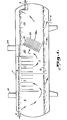
- Fig. 1 discloses a sectioned elevation of a horizontally extended shell 1 in the simplest terms.
- An emulsion of oil and water, as a mixture of polar and non-polar liquids, is introduced into the lefthand end of the shell through conduit 2. Separated by the invention, the oil is removed from shell 1 through upper outlet 3, and water is removed from the shell 1 through lower outlet 4. There may be gas in the emulsion introduced into the shell 1. For the purposes of disclosing the present invention, the gas will be ignored, the invention being directed to the liquid/liquid separation of oil and water.
- the shell 1 is divided into compartments.
- the first compartment 5 indicates that a heat source within this compartment is arranged to be contacted by the well stream flowing through compartment 5.
- the purpose of this arrangement is to elevate the temperature of the well stream as may be required to enhance the liquid/liquid separation carried out by the downstream embodiment of the invention.
- this heat input to the well stream could be supplied by a-heater in conduit 2 established upstream of shell 1.
- Each compartment within shell 1 receives the horizontally flowing liquids.
- the flow of the processed liquids, within each compartment may be directed vertically, but the flow between compartments is significant in its horizontal orientation, .
- some form of substantially horizontal flow space is provided in which a degree of disengagement between the immiscible liquids is expected. Controlled in their horizontal flow, these disengaged liquids have the maximum opportunity to gravitate upward or downward, in separation, without- their flows opposing each other.
- Compartment 6 is downstream of heater compartment 5 and receives the well stream within the temperature range suitable for initiation of the liquid/liquid separation in the electric field of compartment 6.
- the electric field in compartment 6 is disclosed as generated between electrodes 7, the electrodes being charged from a transformer 8.
- the art is replete with the many variations for effective application of electric fields to the resolution of mixtures of relatively polar liquids dispersed in relatively non-polar liquids. This phenomenon has been exhaustively analyzed in the previous Background Art section of this application, including the references incorporated therein.
- the electric field of this compartment 6 may not be required upstream of the embodiment of the present invention.
- the electric field established with the present invention may be adequate to effect coalescence without any preparation by the field within compart- .ment 6.
- the field generated within compartment 6 has the same optional status as the heater of compartment 5.
- the forces generated within these compartments may, or may not, be utilized upstream of the invention.
- both the heat of compartment 5 and the electric field of compartment 6 may be valuable options in a treater as represented within shell 1.
- zone 11 Admittedly, zone 11 is no more than the volume within shell 1 below and downstream of compartment 6. However, this quiescent zone enables a significant amount of coalesced liquids to disengage and gravitate upward, or downward, as a part of the separation goal. By flowing these liquids through compartment 11 horizontally, disengagement of the oil from the water, and the water from the oil, is provided with a minimum of opposing flow which would delay their separation.
- an essential element of the invention is embodied in an inclined plate separator structure 21 having a design for its plates 22 adapted to accept an electric charge from a source 23 which will generate a degrading electric field in the direction of fluid flow through the separator.
- the inclined plates 22 form the array 21 providing parallel passages for the oil/water mixture between the plates. The mixture is first exposed to the full strength of the electric field generated from the source 23, secondly, to the field strength as it degrades, and thirdly, to the surface of the plates upon which the coalescing fluids in the mixture collect and continue their coalescence begun in the electric field.
- a volumetric section lla of the shell 1 is provided for disengagement of the additionally coalesced liquids of the mixture.
- the liquids discharged from the array 21 are given further opportunity to disengage, the oil ascending and the water descending to join their respective collections at the top and bottom of shell 1.
- the disengaging liquids are released essentially horizontally from the array 21 to give as little interference as possible to the ascent of the oil and descent of the water. The remaining arrangements for withdrawal of the oil and water separately from shell 1 become more commentary to the overall process carried out by the disclosed structure.
- Fig. 2 the upper two plates 22, 22' of the array 21 in compartment 20 are shown in sectioned elevation. All the plates of the array are constructed in the same manner. Therefore, to disclose the function of the array as a unit, only two of the plates are disclosed with a.scale large enough to.clearly illustrate their function when formed of selected materials and connected to electrical source 23.
- Each plate is made up of a composite of two sections.
- the first section 24 is formed of electrically conductive material.
- the trailing, or downstream, second section 25 is formed of nonconductive material. Arranged in intimate contact, sections 24 and 25 physically form a single sheet, body, or plate.
- the conductive section 24 is connected to source 23, as will be specifically disclosed in Fig. 3.
- the fluid mixture from disengagement zone 11 flows through the passageway provided plates 22, 22', the plates being uniformly spaced and parallel to each other.
- the parallel plates 22,-22' of array 21 provide a homogeneous electric field of constant strength at the entrance of their passageway, followed by a degrading portion of the field. Note that the degrading of the field is accomplished not by increasing the distance between the plates, as electrodes, with a uniform charge density, but by degrading the potential between the plates in the direction of flow while maintaining the plates at a constant separation distance. In this way, droplet dispersal due to electrical stress is minimized in the low field strength areas of the degrading field.
- the degrading field is achieved by virtue of the insulating properties on the nonconductive section 25 of each plate electrode. Contact with the conductive section 24 at the front of each plate establishes a surface charge on the insulating .section 25 of the same polarity as that imposed upon the conducting material. However, since the insulating material is, by definition, nonconductive, this charge is not distributed equally over its entire surface area. A high density of surface charge is found in that region near the conductive section of the plate, while the density of surface charge decreases in the direction of flow with increasing distance from the conductive: section.
- Zone A is the region between the charged conductive section 24 of the plates.
- Zone B and C are bounded by the insulating, nonconductive sections 25, 25' of plates 22, 22'.
- zone B the electric field is degrading in the direction of flow, while in zone C the electrical field is weak, or non-existent. Therefore, in zones A and B, coalescence is electrically enhanced by the mechanisms already discussed, while zone C functions substantailly as an inclined plate separator with coalescence being mechanically enhanced.
- the relative dimensions of the three zones described in Fig. 2, and the characteristics of the electric fields generated in the zones, are dependent upon a number of design factors. These include, 1) the distance to which the conductive section extends in the direction of flow; 2) the potential applied to the conductive section; 3) the characteristics of the applied potential; 4) the spacing between plates in the array; 5) the charging characteristics of insulating section 25; and 6) the distance to which the insulating section extends in the direction of flow.
- design factors include, 1) the distance to which the conductive section extends in the direction of flow; 2) the potential applied to the conductive section; 3) the characteristics of the applied potential; 4) the spacing between plates in the array; 5) the charging characteristics of insulating section 25; and 6) the distance to which the insulating section extends in the direction of flow.
- design factors include, 1) the distance to which the conductive section extends in the direction of flow; 2) the potential applied to the conductive section; 3) the characteristics of the applied potential; 4) the spacing between plates in the array; 5)
- zones A and B make up a relatively large fraction of the area between adjacent plates and that a high strength electrical field be generated in zone A.
- the dimensions of zone A are, of course, controlled by the dimensions of the conducting section of each plate.
- the dimensions of zone B will be dependent upon the charging characteristics of insulating material. An insulator which readily accepts and retains a surface charge, like fiberglass, is best suited for a gradual decline of surface charge .in the direction of flow.
- the electrical field strength at : the entrance of zone B is dependent upon both the charging characteristics of the insulating material and the potential applied to the conducting section of zone A.
- the electrically enhanced inclined plate separator is to be used as a secondary coalescence device following, for example, a primary device which may, because of the emulsion characteristics, be better suited for coalescing the finer droplets of the dispersed phase, then a relatively large zone B with a relatively weak degrading electrical field may be desirable.
- a relatively small zone A which has been weakly charged and an insulating material, again like fiberglass, which readily accepts and retains a surface charge.
- a weak degrading field may be created in zone B which enhances coalescence through polarization of droplets of the dispersed phase without detrimental hindering of droplet gravitation by the electrophoretic effects.
- Fiberglass may be an acceptable insulating material for the second section of each of the composite plates.
- other insulating materials may be selected in view of the following factors.
- the charging of an insulating material is predominantly a surface phenomenon and not well understood.
- a material with a large charge relaxation time constant may transmit a charge along its surface relatively slowly but is less easily discharged than a material with a smaller charge relaxation time constant.. Therefore, materials with a large charge relaxation time constant are probably best suited for maintaining a relatively stable surface charge gradient.
- Fig. 3 is illustrative of an embodiment of the present invention in which the best features of an electrical coalescing system and an inclined surface separator are combined in one treating device for the purposes of coalescing droplets of a dispersed polar liquid in a non-polar continuous liquid phase.
- a parallel array 21 of plates 22 in which the front section 24 of each plate is an electrical conductor, and the downstream section 25 is formed of an electrically nonconducting material.
- the electrically conductive material on the front of the plate is present along virtually its entire width.
- the electrical circuitry includes a transformer 23 with a primary 23' connected to a source not shown, and a secondary 23" connected on one side to ground and on the other side to section 24 of each plate 22.
- connection of the secondary to the electrodes includes two rectifiers 26 and 27 in parallel.
- Each rectifier is connected to half of the plates 22 in the array 21 in such a way that every other plate is connected to the same rectifier. Connected in this way, every adjacent pair of plates of the array are oppositely charged.
- the rectifiers 26 and 27 may be eliminated from the circuit and one side of the secondary 23" connected to every other plate in the array, while the other side of the secondary 23" is grounded and connected to the remaining plates. Connected in this way, in every adjacent pair of plates in the array, one plate is charged with alternating current, while the other plate is grounded.
- the electrically enhanced inclined plate separator represented by Fig. 3 must be housed in a vessel such as represented by compartment 20 in shell 1.
- the design of this vessel is not indicated in Fig. 3 since the design of the vessel will be dependent upon the application in which the invention is used.
- baffles also not shown, direct the flow of the emulsion in an essentially horizontal fashion into the plate array. Droplets of dispersed phase, here represented by water, which coalesce in the electric fields, are collected in areas of low electric field strength by their gravitation to the surfaces of plates. Further coalescence takes place on these surfaces as droplets travel down the plates to the exit region of the plate array.
- Coalesced droplets of dispersed phase are discharged from the ends of each plate into a ⁇ quiescent disengagement zone 11a and gravitate to the interface between the water and oil. Dry oil, is removed from the top of the quiescent zone while water is removed from a body of water in the bottom of the treating vessel.
- the present invention might be considered closely allied to the invention of U. S. Patent Application, K. L. Sublette, No. 345,963, filed February 5, 1982.
- the inclined plate separator was separate from and located downstream of an electric field.
- the sequential effects of the field and sqparator effectively coalesced relatively polar liquids dispersed in the continuous phase of relatively non-polar liquids.
- the present application goes beyond this concept by establishing an electric field in the passageways of the inclined plates of the separator and degrading this field in the direction of flow.
- the parallel plates of the separator array are referred to as "composite", being made up of a front section of electrically conductive material, and a trailing section of electrically nonconductive material.
- the resulting electric field established in the passageways of the inclined plates is analyzed in its dimensions and strength by designating dividing zones.
- the source of electrical energy connected to the conductive section of the composite plates is preferably arranged to charge adjacent plates with different polarity. However, no specific connection between the electrical source and plates is to be taken as limiting the scope of the invention.
Landscapes
- Chemical & Material Sciences (AREA)
- Chemical Kinetics & Catalysis (AREA)
- Oil, Petroleum & Natural Gas (AREA)
- Physics & Mathematics (AREA)
- Thermal Sciences (AREA)
- Engineering & Computer Science (AREA)
- General Chemical & Material Sciences (AREA)
- Organic Chemistry (AREA)
- Electrostatic Separation (AREA)
- Cell Separators (AREA)
- Production Of Liquid Hydrocarbon Mixture For Refining Petroleum (AREA)
Applications Claiming Priority (2)
| Application Number | Priority Date | Filing Date | Title |
|---|---|---|---|
| US360253 | 1982-03-22 | ||
| US06/360,253 US4469582A (en) | 1982-03-22 | 1982-03-22 | Electrically enhanced inclined plate separator |
Publications (3)
| Publication Number | Publication Date |
|---|---|
| EP0089471A2 true EP0089471A2 (fr) | 1983-09-28 |
| EP0089471A3 EP0089471A3 (en) | 1983-12-14 |
| EP0089471B1 EP0089471B1 (fr) | 1986-11-20 |
Family
ID=23417222
Family Applications (1)
| Application Number | Title | Priority Date | Filing Date |
|---|---|---|---|
| EP83100851A Expired EP0089471B1 (fr) | 1982-03-22 | 1983-01-29 | Séparateur électrique à plaques inclinées |
Country Status (6)
| Country | Link |
|---|---|
| US (1) | US4469582A (fr) |
| EP (1) | EP0089471B1 (fr) |
| JP (1) | JPS58170508A (fr) |
| KR (1) | KR870000334B1 (fr) |
| CA (1) | CA1201412A (fr) |
| MX (1) | MX154574A (fr) |
Cited By (5)
| Publication number | Priority date | Publication date | Assignee | Title |
|---|---|---|---|---|
| AU567048B2 (en) * | 1984-05-30 | 1987-11-05 | Shell Internationale Research Maatschappij B.V. | Separation by electrostatic coalescence |
| EP0175191A3 (en) * | 1984-09-19 | 1987-12-02 | National Tank Company | Method and apparatus for separating oilfield emulsions |
| RU2250127C1 (ru) * | 2003-08-25 | 2005-04-20 | Открытое акционерное общество "Научно-исследовательский и проектный институт по переработке газа" (ОАО "НИПИгазпереработка") | Аппарат для разделения водонефтяной эмульсии |
| WO2014119978A1 (fr) * | 2013-01-29 | 2014-08-07 | González Estrada Pedro Gabriel | Électropurification accélérée de biodiesel |
| CN106110710A (zh) * | 2016-07-04 | 2016-11-16 | 华东理工大学 | 一种对硫酸烷基化反应流出物进行酸烃分离的装置与方法 |
Families Citing this family (48)
| Publication number | Priority date | Publication date | Assignee | Title |
|---|---|---|---|---|
| US4624763A (en) * | 1984-04-17 | 1986-11-25 | Exxon Research And Engineering Company | Separation of dispersed phase from phase mixture |
| US4624765A (en) * | 1984-04-17 | 1986-11-25 | Exxon Research And Engineering Company | Separation of dispersed liquid phase from continuous fluid phase |
| CA1306442C (fr) * | 1984-04-17 | 1992-08-18 | Exxon Research And Engineering Company | Methode d'aspiration d'une phrase dispersee d'une phase continue, et appareil connexe |
| US4661226A (en) * | 1984-04-17 | 1987-04-28 | Exxon Research And Engineering Company | Separation of dispersed phase from phase mixture |
| US4634510A (en) * | 1984-04-17 | 1987-01-06 | Exxon Research And Engineering Company | Clarifying a contaminated fluid |
| CA1289510C (fr) * | 1984-04-17 | 1991-09-24 | Douglas G. Ryan | Separation centrifuge de la phase disperse d'une phase continue a l'aide de charges electrostatiques |
| US4624764A (en) * | 1984-04-17 | 1986-11-25 | Exxon Research And Engineering Company | Separation of dispersed phase from continuous fluid phase |
| US4904367A (en) * | 1985-10-15 | 1990-02-27 | Exxon Research And Engineering Company | Removing haze from dewaxed hydrocarbon oil mixture boiling in the lubricating oil range |
| US4702817A (en) * | 1985-10-21 | 1987-10-27 | Exxon Research And Engineering Company | Removing haze from hydrocarbon oil mixture boiling in the lubricating oil range |
| US4702815A (en) * | 1986-05-05 | 1987-10-27 | National Tank Company | Distributed charge composition electrodes and desalting system |
| US5554301A (en) * | 1995-05-08 | 1996-09-10 | Universal Environmental Technologies, Inc. | Water clarification system |
| US5958213A (en) * | 1996-09-18 | 1999-09-28 | Konica Corporation | Water treatment method and apparatus for water containing oil droplets |
| US5986133A (en) * | 1997-06-30 | 1999-11-16 | The Texas A&M University System | Recovery of fermentation salts from dilute aqueous solutions |
| US5865992A (en) * | 1997-09-29 | 1999-02-02 | Edmondson; Jerry M. | Oil, water and gas separator |
| AU9512398A (en) * | 1997-09-30 | 1999-04-23 | Xonex Corporation | Fluid filtration, recirculation and delivery apparatus and method |
| US6315898B1 (en) * | 2000-04-27 | 2001-11-13 | Hendrix R. Bull | Emulsion treating method and apparatus |
| NO316109B1 (no) * | 2001-11-07 | 2003-12-15 | Aibel As | En coalescer anordning |
| US6673135B2 (en) * | 2002-02-08 | 2004-01-06 | National Tank Company | System and method of separating entrained immiscible liquid component of an inlet stream |
| FI112328B (fi) * | 2002-05-16 | 2003-11-28 | Outokumpu Oy | Menetelmä ja laitteisto neste-nesteuuton dispersion ohjaamiseksi |
| FI112039B (fi) * | 2002-05-16 | 2003-10-31 | Outokumpu Oy | Menetelmä ja laitteisto neste-nesteuuton dispersion tiivistämiseksi |
| FI113244B (fi) * | 2002-05-16 | 2004-03-31 | Outokumpu Oy | Menetelmä ja laitteisto neste-nesteuuton dispersion erottumisen hallitsemiseksi |
| CA2387257C (fr) | 2002-05-23 | 2009-07-28 | Suncor Energy Inc. | Conditionneur fixe de desaeration pour le traitement de la mousse de bitume |
| US6860979B2 (en) * | 2002-08-07 | 2005-03-01 | National Tank Company | Dual frequency electrostatic coalescence |
| US7351320B2 (en) * | 2002-08-07 | 2008-04-01 | National Tank Company | Multiple frequency electrostatic coalescence |
| US7758738B2 (en) | 2002-08-07 | 2010-07-20 | National Tank Company | Separating multiple components of a stream |
| US7736501B2 (en) | 2002-09-19 | 2010-06-15 | Suncor Energy Inc. | System and process for concentrating hydrocarbons in a bitumen feed |
| CA2400258C (fr) | 2002-09-19 | 2005-01-11 | Suncor Energy Inc. | Separateur de mousse bitumineuse a plaques inclinees et methode de traitement d'hydrocarbures a l'aide d'un cyclone separateur |
| CA2455011C (fr) | 2004-01-09 | 2011-04-05 | Suncor Energy Inc. | Traitement de mousse bitumineuse par injection de vapeur en ligne |
| DE202004007039U1 (de) * | 2004-05-03 | 2005-06-30 | Eichenauer Heizelemente Gmbh & Co. Kg | Vorrichtung zum Trennen von Fluidströmen in einer Heizeinrichtung |
| CA2526336C (fr) | 2005-11-09 | 2013-09-17 | Suncor Energy Inc. | Methode et appareil pour extraire du sable bitumineux |
| US8168071B2 (en) | 2005-11-09 | 2012-05-01 | Suncor Energy Inc. | Process and apparatus for treating a heavy hydrocarbon feedstock |
| US8591714B2 (en) * | 2007-04-17 | 2013-11-26 | National Tank Company | High velocity electrostatic coalescing oil/water separator |
| JP5548338B2 (ja) * | 2008-01-31 | 2014-07-16 | 住友化学株式会社 | 沈降型液液分離器 |
| NO330637B1 (no) * | 2009-05-22 | 2011-05-30 | Aker Process Systems As | Emulsjonsbehandlingsanordning |
| WO2011071113A1 (fr) * | 2009-12-10 | 2011-06-16 | 株式会社Ihi | Dispositif de séparation huile-eau et dispositif de raffinage |
| CA2689021C (fr) | 2009-12-23 | 2015-03-03 | Thomas Charles Hann | Appareil et procede de regulation de debit par le truchement d'une caisse aspirante |
| US9095790B2 (en) | 2012-06-08 | 2015-08-04 | Cameron International Corporation | High velocity electrostatic coalescing oil/water separator |
| US9782699B2 (en) | 2015-02-27 | 2017-10-10 | Recovered Energy, Inc. | Liquid refinement |
| US10343088B2 (en) * | 2015-02-27 | 2019-07-09 | Recovered Energy, Inc. | Liquid refinement |
| US10343089B2 (en) | 2015-02-27 | 2019-07-09 | Recovered Energy, Inc. | Liquid refinement |
| US10870592B2 (en) * | 2015-05-15 | 2020-12-22 | Onesubsea Ip Uk Limited | Electrostatic separator |
| US10207202B2 (en) * | 2015-12-04 | 2019-02-19 | Cameron Solutions, Inc. | High flux electrostatic separator for subsea applications |
| US9957447B2 (en) * | 2015-12-22 | 2018-05-01 | Cameron Solutions, Inc. | Electrostatic technology system and process to dehydrate crude oil in a crude oil storage tank of a floating production storage and offloading installation |
| US9914073B2 (en) * | 2015-12-22 | 2018-03-13 | Cameron Solutions, Inc. | Crude oil storage tank with electrostatic internals to dehydrate crude oil within a process train of a floating production storage and offloading installation |
| US11406918B2 (en) * | 2018-04-30 | 2022-08-09 | University Of Houston System | Adjustable particle separator system and method of using same |
| US11491418B2 (en) | 2019-11-27 | 2022-11-08 | Saudi Arabian Oil Company | Floating assembly of inclined channels with an applied electrical field for the accelerated electrostatic separation of water-in-oil dispersions |
| US11560326B2 (en) | 2021-03-08 | 2023-01-24 | Synergy Watercare Solutions Inc. | Fluid treatment system and process |
| CN115367845A (zh) * | 2022-08-25 | 2022-11-22 | 无锡中天固废处置有限公司 | 一种含硅微粉有机废液的处理方法 |
Family Cites Families (8)
| Publication number | Priority date | Publication date | Assignee | Title |
|---|---|---|---|---|
| GB365018A (en) * | 1931-07-29 | 1932-01-14 | Metallgesellschaft Ag | Improvements in or relating to apparatus for the electrical precipitation of suspended particles from gaseous fluids |
| US2092491A (en) * | 1935-09-30 | 1937-09-07 | Socony Vacuum Oil Co Inc | Method and apparatus for electrical demulsification |
| US2478934A (en) * | 1942-03-13 | 1949-08-16 | Eleanor H Morse | Electric apparatus for separating oils from mixtures |
| US2846389A (en) * | 1954-06-09 | 1958-08-05 | Exxon Research Engineering Co | Electrode for electrical coalescence |
| US3476678A (en) * | 1966-06-06 | 1969-11-04 | Forrest L Murdock Sr | Horizontal electric emulsion treater |
| NL141790B (nl) * | 1968-08-23 | 1955-06-15 | Petrolite Corp | Elektrische behandelingsinrichting voor het verwijderen van gedispergeerd materiaal uit minerale olie. |
| US4181591A (en) * | 1976-08-10 | 1980-01-01 | King Arthur S | Electrostatic and electrolytic clarifier apparatus |
| US4354861A (en) * | 1981-03-26 | 1982-10-19 | Kalt Charles G | Particle collector and method of manufacturing same |
-
1982
- 1982-03-22 US US06/360,253 patent/US4469582A/en not_active Expired - Lifetime
-
1983
- 1983-01-29 EP EP83100851A patent/EP0089471B1/fr not_active Expired
- 1983-02-23 CA CA000422265A patent/CA1201412A/fr not_active Expired
- 1983-03-10 MX MX196527A patent/MX154574A/es unknown
- 1983-03-17 KR KR1019830001083A patent/KR870000334B1/ko not_active Expired
- 1983-03-22 JP JP58046084A patent/JPS58170508A/ja active Granted
Cited By (6)
| Publication number | Priority date | Publication date | Assignee | Title |
|---|---|---|---|---|
| AU567048B2 (en) * | 1984-05-30 | 1987-11-05 | Shell Internationale Research Maatschappij B.V. | Separation by electrostatic coalescence |
| EP0175191A3 (en) * | 1984-09-19 | 1987-12-02 | National Tank Company | Method and apparatus for separating oilfield emulsions |
| RU2250127C1 (ru) * | 2003-08-25 | 2005-04-20 | Открытое акционерное общество "Научно-исследовательский и проектный институт по переработке газа" (ОАО "НИПИгазпереработка") | Аппарат для разделения водонефтяной эмульсии |
| WO2014119978A1 (fr) * | 2013-01-29 | 2014-08-07 | González Estrada Pedro Gabriel | Électropurification accélérée de biodiesel |
| CN106110710A (zh) * | 2016-07-04 | 2016-11-16 | 华东理工大学 | 一种对硫酸烷基化反应流出物进行酸烃分离的装置与方法 |
| CN106110710B (zh) * | 2016-07-04 | 2018-08-31 | 华东理工大学 | 一种对硫酸烷基化反应流出物进行酸烃分离的装置与方法 |
Also Published As
| Publication number | Publication date |
|---|---|
| JPS6260927B2 (fr) | 1987-12-18 |
| KR870000334B1 (ko) | 1987-03-04 |
| US4469582A (en) | 1984-09-04 |
| EP0089471B1 (fr) | 1986-11-20 |
| CA1201412A (fr) | 1986-03-04 |
| EP0089471A3 (en) | 1983-12-14 |
| KR840003822A (ko) | 1984-10-04 |
| MX154574A (es) | 1987-09-30 |
| JPS58170508A (ja) | 1983-10-07 |
Similar Documents
| Publication | Publication Date | Title |
|---|---|---|
| EP0089471B1 (fr) | Séparateur électrique à plaques inclinées | |
| US4581120A (en) | Method and apparatus for separating oilfield emulsions | |
| US6860979B2 (en) | Dual frequency electrostatic coalescence | |
| EP0096739B1 (fr) | Rupture d'émulsions à l'aide de champs électriques multiples | |
| US4252631A (en) | Electrostatic coalescence system with independent AC and DC hydrophilic electrodes | |
| US4116790A (en) | Method and apparatus for separation of fluids with an electric field and centrifuge | |
| US10383181B2 (en) | RF heating of a dielectric fluid | |
| US7351320B2 (en) | Multiple frequency electrostatic coalescence | |
| CA1100096A (fr) | Traduction non-disponible | |
| CA1273896A (fr) | Separation d'une phase liquide en dispersion d'une phase continue par recours a la coalescence par voie electrostatique | |
| EP0085847A1 (fr) | Procédé et dispositif pour déshydrater électrostatiquement et mécaniquement des émulsions provenant des gisements pétrolifères | |
| US4224124A (en) | Electrostatic coalescing system | |
| US10786757B2 (en) | Compact electrocoalescer with conical frustum electrodes | |
| Sjoblom et al. | Effect of DC Electric Fields on Liquid-Liquid Settling | |
| Warren et al. | The Electrodynamic Contactor for Extraction |
Legal Events
| Date | Code | Title | Description |
|---|---|---|---|
| PUAI | Public reference made under article 153(3) epc to a published international application that has entered the european phase |
Free format text: ORIGINAL CODE: 0009012 |
|
| AK | Designated contracting states |
Designated state(s): FR GB IT NL |
|
| PUAL | Search report despatched |
Free format text: ORIGINAL CODE: 0009013 |
|
| AK | Designated contracting states |
Designated state(s): FR GB IT NL |
|
| 17P | Request for examination filed |
Effective date: 19840224 |
|
| GRAA | (expected) grant |
Free format text: ORIGINAL CODE: 0009210 |
|
| RAP1 | Party data changed (applicant data changed or rights of an application transferred) |
Owner name: NATIONAL TANK COMPANY |
|
| AK | Designated contracting states |
Kind code of ref document: B1 Designated state(s): FR GB IT NL |
|
| ITF | It: translation for a ep patent filed | ||
| ET | Fr: translation filed | ||
| PLBE | No opposition filed within time limit |
Free format text: ORIGINAL CODE: 0009261 |
|
| STAA | Information on the status of an ep patent application or granted ep patent |
Free format text: STATUS: NO OPPOSITION FILED WITHIN TIME LIMIT |
|
| 26N | No opposition filed | ||
| ITTA | It: last paid annual fee | ||
| REG | Reference to a national code |
Ref country code: GB Ref legal event code: IF02 |
|
| PGFP | Annual fee paid to national office [announced via postgrant information from national office to epo] |
Ref country code: FR Payment date: 20020103 Year of fee payment: 20 |
|
| PGFP | Annual fee paid to national office [announced via postgrant information from national office to epo] |
Ref country code: GB Payment date: 20020104 Year of fee payment: 20 |
|
| PGFP | Annual fee paid to national office [announced via postgrant information from national office to epo] |
Ref country code: NL Payment date: 20020107 Year of fee payment: 20 |
|
| PG25 | Lapsed in a contracting state [announced via postgrant information from national office to epo] |
Ref country code: GB Free format text: LAPSE BECAUSE OF EXPIRATION OF PROTECTION Effective date: 20030128 |
|
| PG25 | Lapsed in a contracting state [announced via postgrant information from national office to epo] |
Ref country code: NL Free format text: LAPSE BECAUSE OF EXPIRATION OF PROTECTION Effective date: 20030129 |
|
| REG | Reference to a national code |
Ref country code: GB Ref legal event code: PE20 Effective date: 20030128 |
|
| NLV7 | Nl: ceased due to reaching the maximum lifetime of a patent |
Effective date: 20030129 |