EP0089595A2 - Verfahren zum Durchschneiden eines vorzugsweise bandförmigen sich bewegenden Gewebes aus reissbarem Material und Mittel zur Durchführung des Verfahrens - Google Patents
Verfahren zum Durchschneiden eines vorzugsweise bandförmigen sich bewegenden Gewebes aus reissbarem Material und Mittel zur Durchführung des Verfahrens Download PDFInfo
- Publication number
- EP0089595A2 EP0089595A2 EP83102509A EP83102509A EP0089595A2 EP 0089595 A2 EP0089595 A2 EP 0089595A2 EP 83102509 A EP83102509 A EP 83102509A EP 83102509 A EP83102509 A EP 83102509A EP 0089595 A2 EP0089595 A2 EP 0089595A2
- Authority
- EP
- European Patent Office
- Prior art keywords
- web
- reel
- cutting
- round
- cut
- Prior art date
- Legal status (The legal status is an assumption and is not a legal conclusion. Google has not performed a legal analysis and makes no representation as to the accuracy of the status listed.)
- Granted
Links
- 239000000463 material Substances 0.000 title claims abstract description 71
- 238000000034 method Methods 0.000 title claims abstract description 13
- 238000004804 winding Methods 0.000 description 4
- 230000006978 adaptation Effects 0.000 description 1
- 239000012530 fluid Substances 0.000 description 1
Images


Classifications
-
- B—PERFORMING OPERATIONS; TRANSPORTING
- B65—CONVEYING; PACKING; STORING; HANDLING THIN OR FILAMENTARY MATERIAL
- B65H—HANDLING THIN OR FILAMENTARY MATERIAL, e.g. SHEETS, WEBS, CABLES
- B65H19/00—Changing the web roll
- B65H19/22—Changing the web roll in winding mechanisms or in connection with winding operations
- B65H19/2238—The web roll being driven by a winding mechanism of the nip or tangential drive type
-
- B—PERFORMING OPERATIONS; TRANSPORTING
- B65—CONVEYING; PACKING; STORING; HANDLING THIN OR FILAMENTARY MATERIAL
- B65H—HANDLING THIN OR FILAMENTARY MATERIAL, e.g. SHEETS, WEBS, CABLES
- B65H19/00—Changing the web roll
- B65H19/22—Changing the web roll in winding mechanisms or in connection with winding operations
- B65H19/26—Cutting-off the web running to the wound web roll
-
- B—PERFORMING OPERATIONS; TRANSPORTING
- B65—CONVEYING; PACKING; STORING; HANDLING THIN OR FILAMENTARY MATERIAL
- B65H—HANDLING THIN OR FILAMENTARY MATERIAL, e.g. SHEETS, WEBS, CABLES
- B65H2301/00—Handling processes for sheets or webs
- B65H2301/30—Orientation, displacement, position of the handled material
- B65H2301/31—Features of transport path
- B65H2301/316—Features of transport path of web roll
- B65H2301/3164—Features of transport path of web roll involving at least two planes containing the roll axis
- B65H2301/31642—L-shaped
-
- B—PERFORMING OPERATIONS; TRANSPORTING
- B65—CONVEYING; PACKING; STORING; HANDLING THIN OR FILAMENTARY MATERIAL
- B65H—HANDLING THIN OR FILAMENTARY MATERIAL, e.g. SHEETS, WEBS, CABLES
- B65H2408/00—Specific machines
- B65H2408/20—Specific machines for handling web(s)
- B65H2408/23—Winding machines
- B65H2408/236—Pope-winders with first winding on an arc of circle and secondary winding along rails
-
- Y—GENERAL TAGGING OF NEW TECHNOLOGICAL DEVELOPMENTS; GENERAL TAGGING OF CROSS-SECTIONAL TECHNOLOGIES SPANNING OVER SEVERAL SECTIONS OF THE IPC; TECHNICAL SUBJECTS COVERED BY FORMER USPC CROSS-REFERENCE ART COLLECTIONS [XRACs] AND DIGESTS
- Y10—TECHNICAL SUBJECTS COVERED BY FORMER USPC
- Y10T—TECHNICAL SUBJECTS COVERED BY FORMER US CLASSIFICATION
- Y10T225/00—Severing by tearing or breaking
- Y10T225/10—Methods
- Y10T225/16—Transversely of continuously fed work
-
- Y—GENERAL TAGGING OF NEW TECHNOLOGICAL DEVELOPMENTS; GENERAL TAGGING OF CROSS-SECTIONAL TECHNOLOGIES SPANNING OVER SEVERAL SECTIONS OF THE IPC; TECHNICAL SUBJECTS COVERED BY FORMER USPC CROSS-REFERENCE ART COLLECTIONS [XRACs] AND DIGESTS
- Y10—TECHNICAL SUBJECTS COVERED BY FORMER USPC
- Y10T—TECHNICAL SUBJECTS COVERED BY FORMER US CLASSIFICATION
- Y10T225/00—Severing by tearing or breaking
- Y10T225/30—Breaking or tearing apparatus
- Y10T225/35—Work-parting pullers [bursters]
-
- Y—GENERAL TAGGING OF NEW TECHNOLOGICAL DEVELOPMENTS; GENERAL TAGGING OF CROSS-SECTIONAL TECHNOLOGIES SPANNING OVER SEVERAL SECTIONS OF THE IPC; TECHNICAL SUBJECTS COVERED BY FORMER USPC CROSS-REFERENCE ART COLLECTIONS [XRACs] AND DIGESTS
- Y10—TECHNICAL SUBJECTS COVERED BY FORMER USPC
- Y10T—TECHNICAL SUBJECTS COVERED BY FORMER US CLASSIFICATION
- Y10T225/00—Severing by tearing or breaking
- Y10T225/30—Breaking or tearing apparatus
- Y10T225/393—Web restrainer
Definitions
- the present invention relates to a method to cut off a preferably band shaped running web of a tearable material and to feed an end of a web of material to a cylinder designed to support the web and round which cylinder the web is wound.
- Said object is obtained by means of a method according to the present invention, which is substantially characterized by a cutting apparatus equipped with a point perforating the web of material at a certain distance from the respective two lateral edges of the web, this preferably taking place at the centre portion of the web, said cutting apparatus in relation to said web performing a movement at a speed, which is lower than the speed of the forward feed of the web, so that the same is torn apart during its continued forward feed from the area of said perforation in direction towards said two edges of the web, and by the free end of the web of material thus cut-off being guided by said cutting apparatus, so that it is introduced between the reel and the portion of the material web, which is running to the reel.
- Said additional object is obtained by means of an arrangement which is substantially characterized by a cutting off means equipped with a point being movably supported in relation to the material web and arranged to move at a speed, which is lower than the feeding speed of the web of material, and moreover being arranged to guide an end of the web of material, so that it is introduced in the pocket formed between the reel and the portion of the web of material running in the direction to the reel.
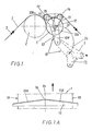
- a web of material which by way of example can comprise a band-shaped paper web fed from a paper making machine, which is not shown on the drawing, is indicated with the digit 1.
- the web 1 is led over a cylinder 2, which is driven by a motor and designed to convey the web 1 in its direction of feed indicated by the arrow 3.
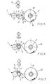
- the empty reels 5 are arranged one by one at a proper moment to be brought in the direction of the arrow 6, as is shown in Fig.
- the reel 5 is suitably brought to rotate in the direction of the arrow 7 in the direction of the web to its position I close to the web 1 and the conveying cylinder 2, as is shown in Fig. 4, which position I is its initial position of readiness to receive the web.
- the web 1 of material extends from the conveying cylinder 2 to an additional reel 5', which is rotatably supported at a certain distance from said empty reel 5 at a winding-up station II, where the web 1 of material is wound up on the reel 5' in a desired degree.
- a cutting-off apparatus which in.the drawings is indicated with the digit 8, can be actuated by means of for example fluid operated pistons, preferably pneumatically operated pistons, preferably being pivoted on a shaft 9 located on the opposite side of the portion 1 of the web of material, as seen in relation to the empty reel 5 and its position I.
- the cutting-off apparatus 8 is formed by a pivoting arm 10, comprising a number of arm elements located on each side of the two lateral edges 1A and 1B respectively of the web of the material, said arm elements for example being connected with each other via the pivoting shaft 9 and via deviating means 11 positioned in the space close to the two free outer ends 10' of the arms of the arm elements.
- Said deviating means 11 suitably comprises a rotatably supported roller 11 extending across the web 1 of material and along the same.
- a pivoting link 12 is suitably supported by said pivoting arm 10 at a distance from the pivoting shaft 9 of the arm, that is chosen in such a manner that the distance suitably coincides with the distance between the pivoting shaft 9 and the centre area of an empty reel 5, which occupies a position at its position I of readiness for the reception of the web, preferably in the area of passage between a straight and an angular portion 10A and 10B respectively of the pivoting arm 10.
- the pivoting link 12 comprises a shaft 12 connected with the respective arm element, suitably via a spring device 12A, said shaft 12 supporting a supporting arm 13 pivoted around said shaft 12, which arm 13 preferably also can be formed by two arm elements located one on each side of the two lateral edges 1A, 1B of the web of the material, said arm elements being connected with each other via a deviation means 14 extending along the web 1 and across the feeding direction of the same, said deviation means also suitably comprising a rotatably supported roller 14.
- a preferably plough-like knife 15 provided with a point forms part of said cutting-off apparatus 8 and is suitably rigidly connected with said supporting arm 13, which is pivoted on the pivot shaft 12, said knife 15 having its point 16 facing in such a direction that it is brought towards the web 1 in the direction of the arrow 17 in counter-clockwise direction in the drawings.
- the point 16 is then suitably arranged to actuate along a plane, that extends through the centre line 18 of the w P b, and the two diverging front sides 15A and 15B respectively of the knife extend across the web 1 of the material outside of said two lateral edges lA, 1B.
- the cutting-off apparatus 8 is subsequently pivoted in the direction of the arrow 20 against the portion 1' of the web, so that the roller 11 of the deviation means is brought to rotate as a consequence of its contact with the web 1, thereby winding up the web 1 round the reel 5 in the direction of the arrow 21 to the end position illustrated, in Fig. 6.
- the supporting arm 13, with which the knife 15 is connected is subsequently actuated by means of for example pneumatic power pistons, so that it pivots round the shaft 12 from the starting position shown in Figs. 1 and 6 in the direction of the arrow 17 towards the roller 11 and the web 1 of the material, which web 1 in said position runs along the outer mantle surface of the reel 5 and is deviated round the deviating means 11.
- the free torn-off forward point portion 1D of the web of the material is guided by the knife 15, forming part of the cutting-off apparatus 8, between the reel 5 and the portion 1 1 of the web of the material, which runs to the reel 5, to a pocket 25, which is formed between the same.
- the cutting-off apparatus 8 is pivoted back to its rest position, which is indicated with broken lines in Fig. 1 in the direction of the arrow 26.
- the new reel 5 is subsequently displaced by means of suitable means, not shown in the drawings, to the position I I, where the previous reel 23 was supported, and which is intended to be the site for the winding-up operation of the new reel.
Landscapes
- Replacement Of Web Rolls (AREA)
- Auxiliary Devices For And Details Of Packaging Control (AREA)
- Control And Other Processes For Unpacking Of Materials (AREA)
- Professional, Industrial, Or Sporting Protective Garments (AREA)
- Solid-Sorbent Or Filter-Aiding Compositions (AREA)
- Materials For Medical Uses (AREA)
Priority Applications (1)
| Application Number | Priority Date | Filing Date | Title |
|---|---|---|---|
| AT83102509T ATE29865T1 (de) | 1982-03-15 | 1983-03-14 | Verfahren zum durchschneiden eines vorzugsweise bandfoermigen sich bewegenden gewebes aus reissbarem material und mittel zur durchfuehrung des verfahrens. |
Applications Claiming Priority (2)
| Application Number | Priority Date | Filing Date | Title |
|---|---|---|---|
| SE8201606 | 1982-03-15 | ||
| SE8201606A SE451833B (sv) | 1982-03-15 | 1982-03-15 | Forfarande och anordning for att kapa en rorlig bandformig materialbana samt tillfora en materialbaneende till en ny upplindningsrulle |
Publications (3)
| Publication Number | Publication Date |
|---|---|
| EP0089595A2 true EP0089595A2 (de) | 1983-09-28 |
| EP0089595A3 EP0089595A3 (en) | 1984-07-04 |
| EP0089595B1 EP0089595B1 (de) | 1987-09-23 |
Family
ID=20346259
Family Applications (1)
| Application Number | Title | Priority Date | Filing Date |
|---|---|---|---|
| EP83102509A Expired EP0089595B1 (de) | 1982-03-15 | 1983-03-14 | Verfahren zum Durchschneiden eines vorzugsweise bandförmigen sich bewegenden Gewebes aus reissbarem Material und Mittel zur Durchführung des Verfahrens |
Country Status (6)
| Country | Link |
|---|---|
| US (1) | US4515321A (de) |
| EP (1) | EP0089595B1 (de) |
| AT (1) | ATE29865T1 (de) |
| DE (1) | DE3373804D1 (de) |
| FI (1) | FI75786C (de) |
| SE (1) | SE451833B (de) |
Cited By (6)
| Publication number | Priority date | Publication date | Assignee | Title |
|---|---|---|---|---|
| EP0395893A1 (de) * | 1989-05-02 | 1990-11-07 | Sulzer-Escher Wyss Gmbh | Vorrichtung zum Auf- oder Umrollen einer Papierbahn |
| US5151077A (en) * | 1991-07-31 | 1992-09-29 | Ark, Inc. | Method and apparatus for perforating material |
| WO1999006313A1 (de) * | 1997-07-30 | 1999-02-11 | Gottlieb Looser | Wickelverfahren, bahntrennvorrichtung und bahnwickler |
| EP0957054A1 (de) * | 1998-03-16 | 1999-11-17 | Voith Sulzer Papiertechnik Patent GmbH | Wickelmaschine und Verfahren zum Aufwickeln einer Materialbahn |
| US6029927A (en) * | 1997-03-13 | 2000-02-29 | Voith Sulzer Papiermaschinen Gmbh | Reeling machine and a process to reel a web |
| EP0997418A1 (de) * | 1998-10-22 | 2000-05-03 | Voith Sulzer Papiertechnik Patent GmbH | Verfahren zum Durchtrennen einer laufenden Materialbahn und Vorrichtung zur Durchführung des Verfahrens |
Families Citing this family (21)
| Publication number | Priority date | Publication date | Assignee | Title |
|---|---|---|---|---|
| DE3914776C2 (de) * | 1989-05-05 | 1994-09-29 | Krantz Textiltechnik Gmbh | Verfahren und Vorrichtung zum Aufwickeln und Querschneiden einer laufenden Warenbahn |
| DE4209630A1 (de) * | 1992-03-25 | 1993-09-30 | Basf Ag | Verfahren und Vorrichtung zum Trennen einer Warenbahn |
| US5427294A (en) * | 1993-11-12 | 1995-06-27 | Reynolds Consumer Products Inc. | Method and apparatus for breaking film perforations |
| WO1996011868A1 (en) * | 1994-10-13 | 1996-04-25 | Valmet Corporation | Method in reeling and change device for use in the method |
| FI100324B (fi) * | 1994-12-13 | 1997-11-14 | Valmet Paper Machinery Inc | Menetelmä ja sovitelma radan katkaisemiseksi |
| DE69814883T2 (de) * | 1997-07-15 | 2004-05-19 | Alcoa Inc. | Hochgeschwindigkeitsstreifenübertragung in einer streifen-verarbeitungsanwendung |
| US7364058B2 (en) | 1997-09-26 | 2008-04-29 | Scientific Games International, Inc. | Ticket dispensing apparatus |
| US6669071B1 (en) | 1997-09-26 | 2003-12-30 | Instant Technologies, Incorporated | Lottery ticket dispensing apparatus |
| US6609644B1 (en) | 1997-09-26 | 2003-08-26 | Instant Technologies, Inc. | Method of dispensing perforated tickets |
| US5950898A (en) * | 1997-09-26 | 1999-09-14 | Instant Technologies, Incorporated | Lottery ticket dispensing apparatus |
| US6467382B2 (en) * | 2000-02-07 | 2002-10-22 | Spartanics | Extractor for extracting cut partially cut parts from a sheet of material |
| FI111356B (fi) * | 2000-06-22 | 2003-07-15 | Metso Paper Inc | Menetelmä ja laite paperirainan kiinnirullauksessa suoritettavassa vaihdossa |
| US7175127B2 (en) * | 2002-09-27 | 2007-02-13 | C.G. Bretting Manufacturing Company, Inc. | Rewinder apparatus and method |
| US6877689B2 (en) * | 2002-09-27 | 2005-04-12 | C.G. Bretting Mfg. Co., Inc. | Rewinder apparatus and method |
| US7756742B2 (en) * | 2003-07-01 | 2010-07-13 | Scientific Games International, Inc. | System and method for dispensing tickets |
| CN101970321B (zh) * | 2007-10-16 | 2014-04-09 | 格罗特斯工程公司 | 索引卷绕机上卷绕芯的设备 |
| US20090163263A1 (en) * | 2007-12-19 | 2009-06-25 | Scientific Games International, Inc. | Method and System for Multiple In-Lane Lottery Ticket Sales at a Retail Establishment |
| DE102013104978B4 (de) * | 2013-05-15 | 2019-03-14 | PSA Technology S.à.r.l. | Maschine zum Aufwickeln von bahnförmigen Materialien |
| US10672234B2 (en) | 2015-07-17 | 2020-06-02 | Scientific Games International, Inc. | Method and system for enhanced lottery ticket accounting and sales with smart bin dispensers at a retail establishment |
| US10229466B2 (en) | 2015-07-17 | 2019-03-12 | Scientific Games International, Inc. | Method and system for enhanced lottery ticket accounting and sales at a retail establishment level |
| US10373443B2 (en) | 2016-06-21 | 2019-08-06 | Scientific Games International, Inc. | Method and system for enhanced lottery ticket activation and sale at a retail establishment with subsequent billing and accountability of sold tickets |
Family Cites Families (11)
| Publication number | Priority date | Publication date | Assignee | Title |
|---|---|---|---|---|
| US3137456A (en) * | 1959-01-23 | 1964-06-16 | Celanese Corp | Rapid roll changer |
| US3764085A (en) * | 1971-08-16 | 1973-10-09 | Du Pont | Method of and apparatus for handling material |
| GB1453933A (en) * | 1972-12-13 | 1976-10-27 | Agfa Gevaert | Automatic winding and cutting apparatus for webs |
| DE2301193C2 (de) * | 1973-01-11 | 1985-09-19 | Maschinenfabrik Stahlkontor Weser Lenze KG, 3258 Aerzen | Vorrichtung zum Wickelrollenwechsel und zum Quertrennen von schnellaufenden Bahnen |
| US3889892A (en) * | 1973-08-09 | 1975-06-17 | Beloit Corp | Center start surface wind reel with automatic cut-off and transfer |
| US3857524A (en) * | 1973-10-05 | 1974-12-31 | Beloit Corp | Surface enveloper transfer winder |
| US3991924A (en) * | 1975-07-30 | 1976-11-16 | American/Durein Company | Burster mechanism |
| DE2534588A1 (de) * | 1975-08-02 | 1977-02-17 | Weser Lenze Stahlkontor | Vorrichtung zum rollenwechsel und zum quertrennen von mit hoher geschwindigkeit laufenden bahnen bei mehrfach-wickelmaschinen |
| DE2705776A1 (de) * | 1977-02-11 | 1978-08-17 | Voith Gmbh J M | Vorrichtung zum kontinuierlichen wickeln von bahnen, insbesondere papierbahnen, auf wickelkerne |
| US4397410A (en) * | 1978-07-07 | 1983-08-09 | Swingline Inc. | Burster |
| JPS56149941A (en) * | 1980-04-21 | 1981-11-20 | Fuji Tekkosho:Kk | Winder with multiple type turret |
-
1982
- 1982-03-15 SE SE8201606A patent/SE451833B/sv not_active IP Right Cessation
-
1983
- 1983-03-10 FI FI830808A patent/FI75786C/fi not_active IP Right Cessation
- 1983-03-14 EP EP83102509A patent/EP0089595B1/de not_active Expired
- 1983-03-14 AT AT83102509T patent/ATE29865T1/de not_active IP Right Cessation
- 1983-03-14 DE DE8383102509T patent/DE3373804D1/de not_active Expired
- 1983-03-15 US US06/475,480 patent/US4515321A/en not_active Expired - Fee Related
Cited By (8)
| Publication number | Priority date | Publication date | Assignee | Title |
|---|---|---|---|---|
| EP0395893A1 (de) * | 1989-05-02 | 1990-11-07 | Sulzer-Escher Wyss Gmbh | Vorrichtung zum Auf- oder Umrollen einer Papierbahn |
| US5151077A (en) * | 1991-07-31 | 1992-09-29 | Ark, Inc. | Method and apparatus for perforating material |
| US6029927A (en) * | 1997-03-13 | 2000-02-29 | Voith Sulzer Papiermaschinen Gmbh | Reeling machine and a process to reel a web |
| WO1999006313A1 (de) * | 1997-07-30 | 1999-02-11 | Gottlieb Looser | Wickelverfahren, bahntrennvorrichtung und bahnwickler |
| US6305635B1 (en) * | 1997-07-30 | 2001-10-23 | Windmoeller & Hoelscher Kg | Continuous web winding method and device with suction-induced winding start of empty core mandrels |
| EP0957054A1 (de) * | 1998-03-16 | 1999-11-17 | Voith Sulzer Papiertechnik Patent GmbH | Wickelmaschine und Verfahren zum Aufwickeln einer Materialbahn |
| EP0997418A1 (de) * | 1998-10-22 | 2000-05-03 | Voith Sulzer Papiertechnik Patent GmbH | Verfahren zum Durchtrennen einer laufenden Materialbahn und Vorrichtung zur Durchführung des Verfahrens |
| US6464161B1 (en) | 1998-10-22 | 2002-10-15 | Voith Sulzer Papiertechnik Patent Gmbh | Process for severing a traveling material web and device for performing the process |
Also Published As
| Publication number | Publication date |
|---|---|
| DE3373804D1 (en) | 1987-10-29 |
| US4515321A (en) | 1985-05-07 |
| EP0089595B1 (de) | 1987-09-23 |
| FI830808L (fi) | 1983-09-16 |
| SE451833B (sv) | 1987-11-02 |
| SE8201606L (sv) | 1983-09-16 |
| ATE29865T1 (de) | 1987-10-15 |
| FI75786C (fi) | 1988-08-08 |
| EP0089595A3 (en) | 1984-07-04 |
| FI75786B (fi) | 1988-04-29 |
| FI830808A0 (fi) | 1983-03-10 |
Similar Documents
| Publication | Publication Date | Title |
|---|---|---|
| US4515321A (en) | Method to cut off a preferably band shaped running web of tearable material and means to carry out the method | |
| EP0118384A1 (de) | Papierwickelmaschine mit Trennmesser | |
| EP0827483B1 (de) | Umwickler mit befestiger für das wickelende | |
| FI91054C (fi) | Menetelmä ja laite tuoteradan automaattista katkaisua ja rullausta varten | |
| US4516735A (en) | Method and apparatus for winding webs | |
| US4988052A (en) | Device for winding longitudinally separated webs and method of changing finished reels and empty cores | |
| US4932599A (en) | Core loading mechanism for web cutting machines | |
| US4485979A (en) | Device for shaftless winding machines | |
| CA1229547A (en) | Automatic roll change | |
| EP0820946B1 (de) | Verfahren zum Einfädeln einer Papierbahn oder ähnlichem bandförmigem Material in eine Wickelvorrichtung, insbesondere in eine Längsschneide-Wickler, und Vorrichtung zur Durchführung des Verfahrens | |
| FI76390B (fi) | Foerfarande och anordning foer spetsdragning av en bana. | |
| US4157794A (en) | Device and method for rolling up continuous sheets | |
| JPH0158098B2 (de) | ||
| US4951900A (en) | Core loading device for web-slitting machines | |
| US4528794A (en) | Apparatus for temporary storage of paper sheets | |
| EP0042619B1 (de) | Verfahren und Vorrichtung zum Verbinden bahnförmiger Papierbogen, insbesondere für die kontinuierliche Zufuhr an Schnelldruckern | |
| JPH0154256B2 (de) | ||
| EP1615754B1 (de) | Vorrichtung zum halten von strangförmigem gut in schneidmaschinen | |
| US4575016A (en) | Continuous ribbon feed method and system | |
| CN221295564U (zh) | 一种分切机旋转转换式分卷切断机构 | |
| EP0820944A1 (de) | Zuführeinheit für Verpackungsmaterial | |
| US7419117B2 (en) | Apparatus for winding up a web in rolls and a method for cutting off a length of the web | |
| JPH092710A (ja) | シート巻取方法 | |
| JPS60148422A (ja) | 円筒体の表面胴巻装置 | |
| HK1014919A (en) | Rewinder incorporating a tail sealer |
Legal Events
| Date | Code | Title | Description |
|---|---|---|---|
| PUAI | Public reference made under article 153(3) epc to a published international application that has entered the european phase |
Free format text: ORIGINAL CODE: 0009012 |
|
| AK | Designated contracting states |
Designated state(s): AT DE FR GB IT |
|
| PUAL | Search report despatched |
Free format text: ORIGINAL CODE: 0009013 |
|
| 17P | Request for examination filed |
Effective date: 19840323 |
|
| RHK1 | Main classification (correction) |
Ipc: B65H 19/26 |
|
| AK | Designated contracting states |
Designated state(s): AT DE FR GB IT |
|
| GRAA | (expected) grant |
Free format text: ORIGINAL CODE: 0009210 |
|
| AK | Designated contracting states |
Kind code of ref document: B1 Designated state(s): AT DE FR GB IT |
|
| PG25 | Lapsed in a contracting state [announced via postgrant information from national office to epo] |
Ref country code: IT Free format text: LAPSE BECAUSE OF FAILURE TO SUBMIT A TRANSLATION OF THE DESCRIPTION OR TO PAY THE FEE WITHIN THE PRESCRIBED TIME-LIMIT;WARNING: LAPSES OF ITALIAN PATENTS WITH EFFECTIVE DATE BEFORE 2007 MAY HAVE OCCURRED AT ANY TIME BEFORE 2007. THE CORRECT EFFECTIVE DATE MAY BE DIFFERENT FROM THE ONE RECORDED. Effective date: 19870923 Ref country code: FR Free format text: THE PATENT HAS BEEN ANNULLED BY A DECISION OF A NATIONAL AUTHORITY Effective date: 19870923 Ref country code: AT Effective date: 19870923 |
|
| REF | Corresponds to: |
Ref document number: 29865 Country of ref document: AT Date of ref document: 19871015 Kind code of ref document: T |
|
| REF | Corresponds to: |
Ref document number: 3373804 Country of ref document: DE Date of ref document: 19871029 |
|
| EN | Fr: translation not filed | ||
| PLBE | No opposition filed within time limit |
Free format text: ORIGINAL CODE: 0009261 |
|
| STAA | Information on the status of an ep patent application or granted ep patent |
Free format text: STATUS: NO OPPOSITION FILED WITHIN TIME LIMIT |
|
| 26N | No opposition filed | ||
| PGFP | Annual fee paid to national office [announced via postgrant information from national office to epo] |
Ref country code: GB Payment date: 19920316 Year of fee payment: 10 |
|
| PGFP | Annual fee paid to national office [announced via postgrant information from national office to epo] |
Ref country code: DE Payment date: 19920430 Year of fee payment: 10 |
|
| PG25 | Lapsed in a contracting state [announced via postgrant information from national office to epo] |
Ref country code: GB Effective date: 19930314 |
|
| GBPC | Gb: european patent ceased through non-payment of renewal fee |
Effective date: 19930314 |
|
| PG25 | Lapsed in a contracting state [announced via postgrant information from national office to epo] |
Ref country code: DE Effective date: 19931201 |