EP0089644A1 - Mikrotom - Google Patents
Mikrotom Download PDFInfo
- Publication number
- EP0089644A1 EP0089644A1 EP83102708A EP83102708A EP0089644A1 EP 0089644 A1 EP0089644 A1 EP 0089644A1 EP 83102708 A EP83102708 A EP 83102708A EP 83102708 A EP83102708 A EP 83102708A EP 0089644 A1 EP0089644 A1 EP 0089644A1
- Authority
- EP
- European Patent Office
- Prior art keywords
- pivot
- balls
- socket
- misalignment
- axis
- Prior art date
- Legal status (The legal status is an assumption and is not a legal conclusion. Google has not performed a legal analysis and makes no representation as to the accuracy of the status listed.)
- Granted
Links
- 230000033001 locomotion Effects 0.000 claims abstract description 22
- 238000000926 separation method Methods 0.000 claims description 4
- 238000005520 cutting process Methods 0.000 description 15
- 230000000153 supplemental effect Effects 0.000 description 4
- 230000000712 assembly Effects 0.000 description 2
- 238000000429 assembly Methods 0.000 description 2
- 239000004568 cement Substances 0.000 description 2
- 239000007788 liquid Substances 0.000 description 2
- 239000000463 material Substances 0.000 description 2
- 238000000034 method Methods 0.000 description 2
- 238000012986 modification Methods 0.000 description 2
- 230000004048 modification Effects 0.000 description 2
- 238000006073 displacement reaction Methods 0.000 description 1
- 230000000694 effects Effects 0.000 description 1
- 230000008030 elimination Effects 0.000 description 1
- 238000003379 elimination reaction Methods 0.000 description 1
- 239000003292 glue Substances 0.000 description 1
- 230000035939 shock Effects 0.000 description 1
Images

Classifications
-
- G—PHYSICS
- G01—MEASURING; TESTING
- G01N—INVESTIGATING OR ANALYSING MATERIALS BY DETERMINING THEIR CHEMICAL OR PHYSICAL PROPERTIES
- G01N1/00—Sampling; Preparing specimens for investigation
- G01N1/02—Devices for withdrawing samples
- G01N1/04—Devices for withdrawing samples in the solid state, e.g. by cutting
- G01N1/06—Devices for withdrawing samples in the solid state, e.g. by cutting providing a thin slice, e.g. microtome
-
- G—PHYSICS
- G01—MEASURING; TESTING
- G01N—INVESTIGATING OR ANALYSING MATERIALS BY DETERMINING THEIR CHEMICAL OR PHYSICAL PROPERTIES
- G01N1/00—Sampling; Preparing specimens for investigation
- G01N1/02—Devices for withdrawing samples
- G01N1/04—Devices for withdrawing samples in the solid state, e.g. by cutting
- G01N1/06—Devices for withdrawing samples in the solid state, e.g. by cutting providing a thin slice, e.g. microtome
- G01N2001/065—Drive details
Definitions
- This invention relates to a pivot system for a microtome and, in particular, to a supplementary misalignment pivot arrangement for accommodating misalignment of elements in the main pivot system.
- a microtome is a device adapted to provide extremely thin slices of a material for microscopic examination.
- the material to be sliced is mounted to the forward end of an articulable specimen holding arm which is itself pivotally mounted at its opposite end within a yoke.
- the yoke is itself pivotally mounted to the microtome frame and connected to an advance member, as a lead screw.
- the specimen is drawn downwardly over the edge of a knife thereby slicing an extremely thin slice of specimen.
- the slice is collected on the surface of a liquid reservoir.
- the holding arm articulates thus permitting the specimen to be raised above the cutting edge of the knife in anticipation of the next downward cutting stroke.
- United States Patent 4,221,438 discloses an alternative technique.
- one of the balls is introduced into a socket containing molten cement and permitted to situate itself such that when the cement sets up there is an exact matching of the distance between the balls and the sockets.
- one of the sockets is fixed to one of the members while the other of the bearing sockets is mounted on a leaf spring for flexural movement with respect to that member. In this manner deviations in the distances between the balls and the sockets may be accommmodated so that exact matching of the bearing elements may be facilitated.
- This invention relates to a misalignment pivot system for a microtome, and particularly for an ultramicrotome in which a pair of main pivot balls is secured to a first member and corresponding main pivot sockets are provided for mounting onto a second member relatively pivotal with respect to the first member.
- One of the main pivot sockets is itself pivotal with respect to the second member on the supplemental misalignment pivot system.
- the misalignment pivot system includes a fixed.socket and a groove formed on either of the main pivot socket or the first member and a pair of fixed sockets on the other of the main pivot socket or the first member. Corresponding fixed sockets and the socket and groove capture misalignment'pivot balls on which pivotal movement of the main pivot socket with respect to the first member may occur.
- misalignments along the axis of the main pivot balls may be accommodated without the generation of a restoring force which may disrupt precise slicing of the specimen.
- FIG. 1 shown is a highly stylized pictorial representation of a microtome generally indicated by reference numeral 10.
- the misalignment pivot system in accordance with this invention may be used with any microtome apparatus, it is believed to have particular utility when used with an ultramicrotome.
- An ultramicrotome is a device adapted to produce specimen slices with thicknesses on the order of nanometers.
- the microtome 10 includes a frame 12 mounted within an outer casing 14 by any suitable means of attachment, such as the shock mounts 16.
- the frame 12 is a relatively massive member which supports a microtome superstructure indicated by reference character 20 on three contact pads (not shown).
- the superstructure 20 is that portion of the microtome which supports those components important to the cutting process (e.g., the knife and specimen holding arm).
- a stage 24 is adjustably mounted on the superstructure 20 by any suitable attachment mechanism.
- the stage 24 carries a suitable specimen cutting element, such as the knife 26.
- the knife 26 serves to produce a series of thin slices of a specimen 27 as the specimen 27 is drawn over the cutting edge 28 of the knife.
- the slices of the specimen are most commonly collected on the surface of a liquid contained in a boat 30 formed in the knife 24 forwardly of the cutting edge 28.
- the specimen.27 from which slices are cut is supported at the outboard end of a specimen holding arm 34.
- the specimen holding arm 34 is pivotally mounted for articulated movement with respect to a housing member 36 on a retract pivot assembly generally indicated by reference character 40.
- the housing 36 is itself pivotally mounted with respect to a yoke 44 on a cutting pivot assembly 46.
- the yoke 44 is pivotally mounted with respect to the superstructure 20 on an advance.pivot assembly 48.
- the advance pivot assembly 48 is mounted a predetermined distance 50 (exaggerated for clarity of illustration in Figure 1) above the cutting pivot assembly 46 for purposes understood by those in the art.
- the free end of the yoke 44 is secured a predetermined distance 52 below the pivot assembly 48 to an advance mechanism, such as a lead screw 54.
- the advance mechanism is suitably supported for movement with respect to the superstructure 20.
- the operation of the microtome 10 shown in Figure 1 is readily understandable from the foregoing by those skilled in the art.
- the specimen holding arm 34 and the housing 36 pivot with respect to the yoke 44 on the cutting pivot assembly 46 to move the specimen 27 in the direction of the arrow 58 over the cutting edge 28 of the knife 26.
- the specimen holding arm 34 articulates on the retract pivot assembly 40 to permit the specimen 27 to be returned. to a position above the cutting edge 28 preparatory to the next cut.
- the yoke 44 is pivoted with respect to the superstructure 20 on the advance pivot assembly 48 to thereby advance the specimen holding arm 34 in the direction of the arrow 60 prior to the next cut of the specimen 27.
- the magnitude of the advance of the specimen 27 in the direction 60 with respect to the superstructure 20 is functionally related to the ratio of the distances 50 and 52. It is to be understood that suitable cams and actuators for the motions discussed are provided, but that these elements are omitted from the Figures for clarity of illutration.
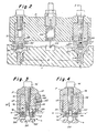
- FIG. 2 and 3 shown is a front section and a side section view of a generalized pivot assembly indicated by the reference character G with which may be used a misalignment pivot system in accordance with this invention and generally indicated by the reference character 64.
- a first member P is mounted for pivotal movement on a pair of mean pivot balls 81 and B2 with respect to a second relatively fixed member F.
- the main pivot balls Bl and B2 are spaced a predetermined distance D apart as measured in a direction parallel to the axis Q-Q' extending through the centers of the balls. Each of the main pivot balls Bl and B2 is respectively received between corresponding pairs of main sockets S1, S3 and S2, S4.
- the socket Sl is secured to the first, pivotable, member P while the sockets S3 and 54'are mounted to the second, relatively fixed, member F.
- the socket S2 is mounted by the supplemental misalignment pivot system 64 for pivotal movement with respect to the first member P.
- the main balls B be secured, as by glue or the like, into the main sockets which are carried on the member with respect to which pivotal motion is to occur. For example, if the first member P is pivotally movable with respect to the second member F, the balls B are glued or otherwise secured into the sockets S3 and.S4.
- the movable socket (S2 in Figures 2 and 3) would therefore be mounted for pivotal movement on the supplemental misalignment pivot system 64 with respect to the pivoting member, i.e., the first member P in the example. It should be understood, however, that the mounting location of the movable socket S2 and its corresponding socket S4 may be reversed. That is, the socket S2 may be mounted on the supplementary pivot system 64 for movement with respect to the relatively fixed member F, while the socket S4 is secured to the pivotable member P.
- the misalignment pivot system 64 includes a pivot support member 68 mounted in a recess 70 provided in the pivotable member P if the socket S2 is to be pivotable with respect to the member P. Of course, if the socket S2 is to pivot with respect to the member F, that member would receive the support 68.
- the misalignment pivot system 64 further includes first and second misalignment pivot balls 72A and 728 respectively.
- the pivot balls 72A and 72B are disposed intermediate fixed sockets 74A and 74B (preferably formed in the pivot socket S2) and a corresponding fixed socket 76 and a V-groove 78 (preferably formed in the pivot support member 68.
- the pivot support member 68 may be arranged to carry only fixed sockets (i.e., a pair of sockets similar to the sockets 74) while the main pivot socket 52 may carry both a fixed socket similar to the socket 76) and a V-groove (similar to the groove 78). Any adjustments in the direction along the axis W-W between the misalignment pivot balls 72A and 72B is accommodated by displacement of the pivot ball 72B to an appropriate position in the groove 78.
- the axis W-W' extends substantially perpendicular to the axis Q-Q' of the main pivot system.
- the pivot support member 68 has a central bore 80 extending therethrough which is counterbored, as at 82, to accommodate a threaded screw 84.
- the screw 84 captures a spring 86 which acts in a direction 88 between the underside of the head of the screw 84 and the bottom of the shoulder formed by the counterbore 82.
- the screw 84 is threaded into the main pivot socket S2 to thereby hold the components of the misalignment pivot system in place while the support 68 is inserted into the recess 70.
- the support 68 is held in place with respect to the member P by a bolt 94.
- a holding spring 100 is provided between the members F and P. It should be noted that the point 102 at which the spring 100 bears against the member F lies on the axis Q-Q'. Thus, the force exerted by the spring 100 is the same through the full pivotal movement of the member P.
- the pivot support 68 includes a recess 106 which registers with a bore 108 provided in the member P.
- a set screw 112 when inserted through the bore 108 and into the recess 106, serves to dispose the axis W-W' extending through the misalignment pivot balls 72 in a substantially perpendicular relationship to the axis Q-Q' extending through the main pivot balls Bl and 82.
- the substantially perpendicular relationship between the axes of the misalignment pivot balls 72 and the main pivot balls may be achieved in an alternate manner.
- a pin 116 is press fit or otherwise secured into some portion of the member P.
- the pivot support 68 is provided with a bore 118 located at a predetermined location with respect to the axis W-W' such that when the pin 116 is received within the bore 118 the axis W-W' is substantially perpendicular to the axis Q-Q'.
- the socket Sl and the support member 68 for the socket S2 may be provided with an adjustment assembly, such as exterior threads 122 and a lock nut 124, whereby the position of the centers of each of the main pivot balls Bl and B2 may be varied with respect to a reference datum.
- the threads 122 and lock nut 124 may be provided on the support member 68.
- the adjustment feature just discussed permits the setting of the offset distance 50 between axis Q-Q' through the main pivot balls provided in the advance pivot assembly 48 with respect to the axis W-W' extending through the supplemental pivot balls provided in the advance pivot assembly.
- any adjustment of one of the main pivot sockets or one of the main pivot balls with respect to the first member P and/or the second member F in the direction of the axis Q-Q' to match the exact separation between the main pivot sockets or the main pivot balls is accommodated by deflection of the pivoting socket S2 in the directions of arrows 128 on the bearing surfaces provided by the misalignment pivot balls 72.
- the pivoting movement of the main pivot socket S2 in the direction of the arrows 128 exact matching of the distances between the main pivot balls and their associated sockets can be accommodated without the imposition of a restoring force generated in flexural pivot systems.
- this invention provides a system whereby exact matching of the distances between the centers of the main pivot balls and their associated sockets is accommodated without flexure of any member and the generation of a concommitant restorative force.
- This restorative force is believed to engender inaccuracies in the uniformity of slices produced and the elimination of the restorative force is therefore believed to be advantageous.
- utilization of the misalignment pivot system hereinabove disclosed provides a structure whereby the main pivot socket may displace in one plane (i.e., the plane of Figure 2) while remaining stiff in a transverse plane.
- the misalignment pivot system of the present invention may be used in any of the pivot assemblies in a microtome wherein relative pivoting motion between members is desired.
- the misalignment pivot system may be used in the retract pivot assembly, in the cutting pivot assembly, in the advance pivot assembly and/or wherever else relative pivotal motion between two members occurs.
- the specimen holding arm 34 and the housing 36 may be respectively construed as the first member P and the second member F.
- the housing 36 and the yoke 44 may be respectively construed as the first member P and the second member F.
- the yoke 44 and the superstructure 20 may be construed as the first member P and the second member F.
- the ability to adjust the main pivot balls relative to a reference datum (the axis W-W of the misalignment pivot balls) through the agency of the threads 122 and lock nut 124 finds especial utility in assisting to define the predetermined distance 50 between the cutting pivot assembly 46 and the advance pivot assembly 48.
Landscapes
- Physics & Mathematics (AREA)
- Health & Medical Sciences (AREA)
- Life Sciences & Earth Sciences (AREA)
- Chemical & Material Sciences (AREA)
- Analytical Chemistry (AREA)
- Biochemistry (AREA)
- General Health & Medical Sciences (AREA)
- General Physics & Mathematics (AREA)
- Immunology (AREA)
- Pathology (AREA)
- Sampling And Sample Adjustment (AREA)
- Crystals, And After-Treatments Of Crystals (AREA)
Priority Applications (1)
| Application Number | Priority Date | Filing Date | Title |
|---|---|---|---|
| AT83102708T ATE25877T1 (de) | 1982-03-24 | 1983-03-18 | Mikrotom. |
Applications Claiming Priority (2)
| Application Number | Priority Date | Filing Date | Title |
|---|---|---|---|
| US06/361,262 US4395075A (en) | 1982-03-24 | 1982-03-24 | Misalignment system for a microtome |
| US361262 | 1982-03-24 |
Publications (2)
| Publication Number | Publication Date |
|---|---|
| EP0089644A1 true EP0089644A1 (de) | 1983-09-28 |
| EP0089644B1 EP0089644B1 (de) | 1987-03-11 |
Family
ID=23421317
Family Applications (1)
| Application Number | Title | Priority Date | Filing Date |
|---|---|---|---|
| EP83102708A Expired EP0089644B1 (de) | 1982-03-24 | 1983-03-18 | Mikrotom |
Country Status (6)
| Country | Link |
|---|---|
| US (1) | US4395075A (de) |
| EP (1) | EP0089644B1 (de) |
| JP (1) | JPS58173449A (de) |
| AT (1) | ATE25877T1 (de) |
| CA (1) | CA1184466A (de) |
| DE (1) | DE3370184D1 (de) |
Families Citing this family (6)
| Publication number | Priority date | Publication date | Assignee | Title |
|---|---|---|---|---|
| DE3410831A1 (de) * | 1984-03-23 | 1985-09-26 | C. Reichert Optische Werke Ag, Wien | Praezisionslager fuer mikrotome, insbesondere ultramikrotome, mit kugeln und/oder kugelkalotten aus geschliffenen amorphen werkstoffen |
| JPH08438B2 (ja) * | 1992-08-12 | 1996-01-10 | 東北ムネカタ株式会社 | プラスチック成形品およびその製造方法と成形用金型 |
| US6799352B2 (en) * | 2002-08-01 | 2004-10-05 | Boeckler Instruments | Zero backlash assembly |
| DE10258553B8 (de) * | 2002-12-14 | 2005-12-08 | Leica Mikrosysteme Gmbh | Verfahren zum automatischen Annähern eines Präparates an ein Messer eines Mikrotoms oder Ultramikrotoms |
| US7437984B2 (en) * | 2004-12-10 | 2008-10-21 | Boeckeler Instruments Inc. | Microtome and ultramicrotome with improved carrier arm |
| WO2015133979A1 (en) * | 2014-03-07 | 2015-09-11 | Kaya Cemalettin | Moving mechanism minimizing the destructive impacts of an earthquake |
Citations (4)
| Publication number | Priority date | Publication date | Assignee | Title |
|---|---|---|---|---|
| GB837413A (en) * | 1955-07-13 | 1960-06-15 | Benjamin Cook | Improvements in or relating to universal pivots |
| AT238963B (de) * | 1963-07-29 | 1965-03-10 | Reichert Optische Werke Ag | Mikrotom, insbesondere Ultramikrotom, mit gelenkig, spielfrei und kraftschlüssig miteinander verbundenen Lagerelementen |
| DE6810260U (de) * | 1968-12-06 | 1969-04-10 | Reichert Optische Werke Ag | Lagereinrichtung fuer mikrotome, insbesondere ultramikrotome |
| US4221438A (en) * | 1978-09-25 | 1980-09-09 | C. Reichert Optische Werke, Ag | Bearing system for the pivot bar of microtomes particularly ultramicrotomes |
Family Cites Families (29)
| Publication number | Priority date | Publication date | Assignee | Title |
|---|---|---|---|---|
| US664118A (en) * | 1899-08-25 | 1900-12-18 | Spencer Lens Co | Microtome. |
| FR398186A (fr) | 1908-12-24 | 1909-05-28 | Henry M De Daillens | Articulations à billes, sans axe et à rattrapage de jeu |
| US1529834A (en) * | 1922-07-21 | 1925-03-17 | Green William Stanley | Apparatus for lining bearings |
| US1638747A (en) * | 1923-06-26 | 1927-08-09 | Skayef Ball Bearing Company | Hanger box |
| US2014643A (en) * | 1933-08-31 | 1935-09-17 | Jacob F J Bakker | Balance block for buildings |
| US2312250A (en) * | 1941-08-22 | 1943-02-23 | Fairbanks Morse & Co | Bearing means |
| US2375322A (en) * | 1944-06-02 | 1945-05-08 | Miniature Prec Bearings | Precision pivot bearing |
| US2636757A (en) * | 1951-04-30 | 1953-04-28 | Bakane Anthony | Ball and socket joint |
| US2901944A (en) * | 1957-08-22 | 1959-09-01 | American Optical Corp | Knife holder clamp for microtome |
| GB921405A (en) | 1961-07-03 | 1963-03-20 | David Danon | Improvements in and relating to microtomes |
| US3184197A (en) * | 1962-08-31 | 1965-05-18 | Sheffield Corp | Supporting device |
| GB975795A (en) * | 1962-10-15 | 1964-11-18 | Reichert Optische Werke Ag | Microtome |
| US3214224A (en) * | 1963-04-17 | 1965-10-26 | Trw Inc | Bearing assembly |
| US3245707A (en) * | 1963-11-06 | 1966-04-12 | Taylor Instrument Co | Pivotal coupling for instrument linkage |
| US3385510A (en) * | 1966-07-29 | 1968-05-28 | Litton Prec Products Inc | Miniature motor driven air blower |
| US3601234A (en) * | 1969-08-04 | 1971-08-24 | American Optical Corp | Microtome electric drive |
| US3628411A (en) * | 1970-01-26 | 1971-12-21 | American Optical Corp | Retractable specimen holder for a microtome |
| GB1352683A (en) | 1970-04-21 | 1974-05-08 | Salter S H | Pivotal assemblies |
| DE2246852A1 (de) * | 1971-11-12 | 1973-05-30 | Reichert Optische Werke Ag | Einrichtung zum einstellen der hoehenlage eines praeparates bei mikrotomen, insbesondere ultramikrotomen |
| US3746129A (en) * | 1972-02-24 | 1973-07-17 | Mount Hope Machinery Ltd | Liquid-lubricated roll |
| AT330480B (de) * | 1972-09-06 | 1976-07-12 | Reichert Optische Werke Ag | Kuhlkammer fur ultramikrotome |
| US3771405A (en) * | 1972-09-08 | 1973-11-13 | Sorvall Inc Ivan | Microtome |
| DE2459218C3 (de) * | 1974-03-29 | 1978-09-07 | C. Reichert Optische Werke Ag, Wien | Vorrichtung zum Transferieren eines tiefgekühlten Präparatschnittes von einem Mikrotom o.dgl. zu einem Mikroskop, insbesondere Elektronenmikroskop |
| US3926085A (en) * | 1974-12-02 | 1975-12-16 | American Optical Corp | Specimen feed for a microtome |
| US4024779A (en) * | 1975-02-14 | 1977-05-24 | C. Reichert Optische Werke | Anti-roll device for ultramicrotomes |
| US3986754A (en) * | 1975-08-18 | 1976-10-19 | The Torrington Company | Bearing with axial fit-up ring |
| US4054999A (en) * | 1975-11-03 | 1977-10-25 | The Timken Company | Adjusting process for bearings |
| US4150593A (en) * | 1978-04-21 | 1979-04-24 | Butler James K | Retractable specimen holder for a rotary microtome |
| SE414384B (sv) * | 1978-11-02 | 1980-07-28 | Sab Ind Ab | Anordning vid en bromsaktuator |
-
1982
- 1982-03-24 US US06/361,262 patent/US4395075A/en not_active Expired - Fee Related
-
1983
- 1983-03-18 DE DE8383102708T patent/DE3370184D1/de not_active Expired
- 1983-03-18 EP EP83102708A patent/EP0089644B1/de not_active Expired
- 1983-03-18 AT AT83102708T patent/ATE25877T1/de not_active IP Right Cessation
- 1983-03-23 JP JP58047329A patent/JPS58173449A/ja active Granted
- 1983-03-24 CA CA000424350A patent/CA1184466A/en not_active Expired
Patent Citations (4)
| Publication number | Priority date | Publication date | Assignee | Title |
|---|---|---|---|---|
| GB837413A (en) * | 1955-07-13 | 1960-06-15 | Benjamin Cook | Improvements in or relating to universal pivots |
| AT238963B (de) * | 1963-07-29 | 1965-03-10 | Reichert Optische Werke Ag | Mikrotom, insbesondere Ultramikrotom, mit gelenkig, spielfrei und kraftschlüssig miteinander verbundenen Lagerelementen |
| DE6810260U (de) * | 1968-12-06 | 1969-04-10 | Reichert Optische Werke Ag | Lagereinrichtung fuer mikrotome, insbesondere ultramikrotome |
| US4221438A (en) * | 1978-09-25 | 1980-09-09 | C. Reichert Optische Werke, Ag | Bearing system for the pivot bar of microtomes particularly ultramicrotomes |
Also Published As
| Publication number | Publication date |
|---|---|
| US4395075A (en) | 1983-07-26 |
| ATE25877T1 (de) | 1987-03-15 |
| CA1184466A (en) | 1985-03-26 |
| JPS58173449A (ja) | 1983-10-12 |
| JPS62448B2 (de) | 1987-01-08 |
| EP0089644B1 (de) | 1987-03-11 |
| DE3370184D1 (en) | 1987-04-16 |
Similar Documents
| Publication | Publication Date | Title |
|---|---|---|
| DE69800550T2 (de) | Ritzwerkzeug | |
| US4561814A (en) | Mechanical tool manipulating method and apparatus | |
| EP0461064A1 (de) | Vorrichtung zum Einrichten und Spannen von Werkstücken | |
| US4395075A (en) | Misalignment system for a microtome | |
| EP0184821B1 (de) | Genaue Positioniervorrichtung | |
| EP0203421A2 (de) | Zoom-Mikroskop mit Kurbel und Gestängemechanismus | |
| DE69004385T2 (de) | Gerät zum Befestigen eines Halteteils auf optischen Linsen. | |
| DE102017114802B4 (de) | Kurzklemmhalter für hochgenaues bohren und justiereinrichtung hierzu | |
| US4495844A (en) | Rotary microtome drive | |
| DE102020104708B4 (de) | Schnelles Messmodul | |
| JPH11502155A (ja) | シートメタル片にインサートを打ち込む機械及び方法 | |
| US4709607A (en) | Rotary cutter blade clamp | |
| JP2991944B2 (ja) | マシンバイス | |
| CN216912266U (zh) | 可调节刀具位置的夹头组件及切削装置 | |
| EP0204958B1 (de) | Vorrichtung zum Schleifen und Läppen von Dichtflächen in Schiebern und dergleichen in situ oder in der Werkstatt | |
| DE2342720C2 (de) | Meßvorrichtung zum Ausmessen von an einem gehäusefesten Halter abgestützten Werkstücken | |
| CN217045588U (zh) | 气压盘式制动器中推力座的工装夹具 | |
| CN114425909A (zh) | 一种用于异型平面承印物的网印夹持定位平台 | |
| WO2008151985A1 (en) | Device for holding and positioning of an object or a workpiece | |
| WO2006089742A2 (de) | Antriebseinheit für ein bewegbares funktionselement | |
| DE102021107928A1 (de) | Anbindung einer verfahrbaren Zusatzsensorik an einer Vorrichtung zum Messen von Form, Lage und Dimensionsmerkmalen an Maschinenelementen | |
| CN222912614U (zh) | 一种轴类零件角度检具 | |
| CN220398922U (zh) | 一种纸板边压粘合取样器 | |
| CN223776621U (zh) | 定位夹具 | |
| DE4120497A1 (de) | Koinzidenzmanipulator |
Legal Events
| Date | Code | Title | Description |
|---|---|---|---|
| PUAI | Public reference made under article 153(3) epc to a published international application that has entered the european phase |
Free format text: ORIGINAL CODE: 0009012 |
|
| 17P | Request for examination filed |
Effective date: 19830318 |
|
| AK | Designated contracting states |
Designated state(s): AT DE FR GB SE |
|
| RAP1 | Party data changed (applicant data changed or rights of an application transferred) |
Owner name: RMC INC. |
|
| GRAA | (expected) grant |
Free format text: ORIGINAL CODE: 0009210 |
|
| AK | Designated contracting states |
Kind code of ref document: B1 Designated state(s): AT DE FR GB SE |
|
| PG25 | Lapsed in a contracting state [announced via postgrant information from national office to epo] |
Ref country code: FR Free format text: THE PATENT HAS BEEN ANNULLED BY A DECISION OF A NATIONAL AUTHORITY Effective date: 19870311 Ref country code: AT Effective date: 19870311 |
|
| REF | Corresponds to: |
Ref document number: 25877 Country of ref document: AT Date of ref document: 19870315 Kind code of ref document: T |
|
| PG25 | Lapsed in a contracting state [announced via postgrant information from national office to epo] |
Ref country code: SE Effective date: 19870319 |
|
| REF | Corresponds to: |
Ref document number: 3370184 Country of ref document: DE Date of ref document: 19870416 |
|
| EN | Fr: translation not filed | ||
| PG25 | Lapsed in a contracting state [announced via postgrant information from national office to epo] |
Ref country code: DE Effective date: 19871201 |
|
| PLBE | No opposition filed within time limit |
Free format text: ORIGINAL CODE: 0009261 |
|
| STAA | Information on the status of an ep patent application or granted ep patent |
Free format text: STATUS: NO OPPOSITION FILED WITHIN TIME LIMIT |
|
| GBPC | Gb: european patent ceased through non-payment of renewal fee | ||
| 26N | No opposition filed | ||
| PG25 | Lapsed in a contracting state [announced via postgrant information from national office to epo] |
Ref country code: GB Free format text: LAPSE BECAUSE OF NON-PAYMENT OF DUE FEES Effective date: 19881122 |
|
| EUG | Se: european patent has lapsed |
Ref document number: 83102708.1 Effective date: 19880616 |