EP0089660A2 - Dispositif d'impression à couleurs multiples pour surfaces d'objets rotatifs - Google Patents
Dispositif d'impression à couleurs multiples pour surfaces d'objets rotatifs Download PDFInfo
- Publication number
- EP0089660A2 EP0089660A2 EP83102778A EP83102778A EP0089660A2 EP 0089660 A2 EP0089660 A2 EP 0089660A2 EP 83102778 A EP83102778 A EP 83102778A EP 83102778 A EP83102778 A EP 83102778A EP 0089660 A2 EP0089660 A2 EP 0089660A2
- Authority
- EP
- European Patent Office
- Prior art keywords
- articles
- article
- holding jigs
- index table
- holding
- Prior art date
- Legal status (The legal status is an assumption and is not a legal conclusion. Google has not performed a legal analysis and makes no representation as to the accuracy of the status listed.)
- Granted
Links
Images


Classifications
-
- B—PERFORMING OPERATIONS; TRANSPORTING
- B41—PRINTING; LINING MACHINES; TYPEWRITERS; STAMPS
- B41F—PRINTING MACHINES OR PRESSES
- B41F17/00—Printing apparatus or machines of special types or for particular purposes, not otherwise provided for
- B41F17/08—Printing apparatus or machines of special types or for particular purposes, not otherwise provided for for printing on filamentary or elongated articles, or on articles with cylindrical surfaces
- B41F17/14—Printing apparatus or machines of special types or for particular purposes, not otherwise provided for for printing on filamentary or elongated articles, or on articles with cylindrical surfaces on articles of finite length
- B41F17/20—Printing apparatus or machines of special types or for particular purposes, not otherwise provided for for printing on filamentary or elongated articles, or on articles with cylindrical surfaces on articles of finite length on articles of uniform cross-section, e.g. pencils, rulers, resistors
- B41F17/22—Printing apparatus or machines of special types or for particular purposes, not otherwise provided for for printing on filamentary or elongated articles, or on articles with cylindrical surfaces on articles of finite length on articles of uniform cross-section, e.g. pencils, rulers, resistors by rolling contact
-
- B—PERFORMING OPERATIONS; TRANSPORTING
- B41—PRINTING; LINING MACHINES; TYPEWRITERS; STAMPS
- B41F—PRINTING MACHINES OR PRESSES
- B41F17/00—Printing apparatus or machines of special types or for particular purposes, not otherwise provided for
- B41F17/28—Printing apparatus or machines of special types or for particular purposes, not otherwise provided for for printing on curved surfaces of conical or frusto-conical articles
Definitions
- the present invention relates to an apparatus for' multi-color printing the surfaces of bodies of rotation and, more particularly, to a multi-color printing apparatus for multi-color printing the surfaces of cylindrical articles such as containers or tubes made of synthetic resins by applying desired colors of ink of ultraviolet-ray set type one by one to their surfaces while being set after each of the ink applications.
- the branket is blotted with a portion of the ink having been applied to the surface of the article so that the mixture of the ink cannot be completely prevented.
- Still another object of the present invention is to ensure a more precise printing registration.
- the present invention has been conceived so as to eliminate the defects, disadvantages and dissatisfactions concomitant with the prior art thus far described, and is featured by the construction that ink in each color is set and dried, immediately after its printing step has been ended, so that subsequent ink in a different color can be applied in an overlapped manner to the ink which has already been applied.
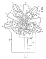
- the multi-color printing apparatus is constructed to comprise: a table mechanism 4 including an index table 44, which supports at positions of an equal center angle (e.g., 18 degrees in the shown embodiment, as shown in Fig. 6) on the circumferential edge portion thereof a plurality of such holding jigs 53 in rotatable manners and in upright positions as are made operative to hold thereon cylindrical articles S made of a synthetic resin and which is made intermittently rotatable or adapted to be indexed at the above-specified equal center angle,- and an article rotating cylinder 46 and a printing rotary ring 50 both of which are coaxially assembled in that index table 44; a plurality of printers 6 which are arranged to face the articles S held on the aforementioned holding jigs 53 without any slippage and stopped at predetermined positions so that they may print the outer circumferences of the articles S in desired colors of ink of ultraviolet-ray set type with desired patterns; a plurality of setting mechanism 3 which are arranged along the transferred passages of the articles
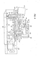
- first and second gear boxes 13 and 14 to which the constant speed rotating force is transmitted through the index unit 12, are equipped with first and second upright shafts 15 and 16, which are made operative to rotate at constant speeds, respectively.
- a rotary shaft which is fixed upright on the mounting platform 102, there is rotatably attached an assembly which is integrally constructed of an intermediate gear 22 meshing with the aforementioned transmission gear 21 and a second drive gear 23 meshing with the second toothed portion 48 of the article rotating cylinder 46 of the table mechanism 4.
- a follower gear 24 which meshes with the second toothed portion 48 of the article rotating cylinder 46 similarly to the aforementioned second drive gear 23.
- a drive roller 26 is fixed to the upper end of the second upright shaft 16 which protrudes upwardfrom the aforementioned mounting platform 102.
- both the loading shaft 28 and the unloading shaft 30 are rotationally driven.
- the holding jigs 53 for holding the articles S without any slippage as are equal to the center angle for the intermittent rotations of that index table 44.
- a rotary gear 54 which is in meshing engagement with the first first toothed portion of the aforementioned article rotating cylinder 46.
- On the upper surface of the aforementioned stationary center portion 40 there are fixed upright a center column 42 for providing the mounting base of the article clamping mechanism 8 and a mounting column 43 for holding holding a rocking arm 81 and the clamping shaft 84 both belonging to that clamping mechanism 8.
- the printing rotary ring 50 which is rotatably mounted on the stationary frame 41 through the bearing 52, has .its toothed portion 51 formed in the outer circumference thereof and meshing with the toothed portion 68 of a drum gear 67 of the corresponding printer 6 so that the drum gear 67 of each printer 6 is rotated at an equal speed by the rotational drive of that first drive gear 20 of the aforementioned rotation transmitting mechanism 2, which is in meshing engagement with the toothed portion 51 of that printing rotary ring 50.
- the printers 6 prints the outer circumferences of the articles S, which are so held by the holding jigs 53 that they are being continuously rotated at a. constant speed, with desired patterns in desired colors of ultraviolet-ray set type ink.
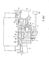
- a printer base plate 73 On a printer base plate 73, there are mounted an inking . roller unit 60, a printing drum 61 formed with the pattern to be printed, and the branket 62 for transferring the desired color of ultraviolet-ray set type ink to the outer circumference of the article S.
- a drum gear 63 is fixed to that lower end of a drum shaft 64 fixing the printing drum 61 in a rotatable manner to that printer base plate 73, which protrudes downward from this base plate 73.
- a branket gear 65 to mesh with the aforementioned drum gear 63 is fixed to that lower end of a branket shaft 66 fixing the branket 62 in a rotatable manner to the printer base plate 73, which protrudes downward from this base plate 73.
- the construction'that the rotating force of the printing rotary ring 50 is to be transmitted to the branket shaft 66 through the drum gear 67 having the equal-speed joints 70 and the rotary shaft 71 is intended to ensure the accurate transmission of the constant rotating speed, even if the branket shaft 66 takes the inclined position as in the shown embodiment, because the branket shaft 66 is inclined in accordance with the shape of the article S to be printed with respect to the printing rotary ring 50 rotating in a predetermined position at all times.
- the branket 62 has its outer circumference divided, as shown in Fig. 8, into a land surface portion 62a, which is used to transfer the ink from the printing drum 61 to the surface of the article S, and a recessed surface portion 62b which is so stepwise recessed inward from that land surface portion 62a that it may not abut against the outer circumference of the article S.
- the circumferential length of the printing land surface portion 62a is set to be twice as large as that of the outer circumferential portion of the article S having a circumferential speed equal to that of the branket 62 so that the smooth and reliable print of the article S may be achieved.
- This limitation is intended to ensure the unloading operation of the articles S from the holding jigs 53 at the stop position T 18 , i.e., at the unloading position.
- the rotating force thus transmitted to the first upright shaft 15 is transmitted to the printing rotary ring 50, which is in meshing engagement with the first drive gear 20 fixed to the upper end of that first upright shaft 15, thereby to rotate those drum gears 67 of the respective printers 6, which are in meshing engagement with that printing rotary ring 50, until it rotationally drives the printing drums 61 and brankets 62 of the respective printers 6 at the predetermined speed in the same direction.
- the transmission gear 21 is mounted on the upper end of the first upright shaft 15 separately of the first drive gear 20, and the second drive gear 23, which is coaxially fixed to the intermediate gear 22 meshing with that transmission gear 21, is in meshing engagement with the second toothed portion 48 of the article rotating cylinder 46.
- This article rotating cylinder 46 is rotationally driven at a speed determined by the number of the teeth of the intermediate gear 22 thereby to rotate the holding jigs 53, which have their rotary gears 54 meshing with that first toothed portion 47, at the desired rotational speed, i.e., at the desired r.p.m.
- the holding jigs 53 are driven at such an r.p.m.,that the circumferential speed of the outer circumferences of the articles S held thereon becomes identical to that of the brankets 62, and the clamping shafts 84 are rotationally driven at the same speed as the aforementioned holding jigs 53.
- the corresponding branket 62 rotating at the constant speed has its rotational position set such that its recessed surface portion 62b faces the article S under consideration.
- the article S having intermittently revolved is not subjected to the printing process simultaneously as it stops at that printing position.
- the article S having been subjected at the stop position T 6 to the setting treatment is indexed to the stop position T 8 , i.e., the second printing position, in which it is additionally printed with the ink in the second color similarly to the aforementioned printing process at the first printing position.
- each holding jig 53 and the brankets 62 are coupled by the meshing engagement between the first upright shaft 15 and the gears, the circumferential position of each holding jig 53 at the instant when the indexed revolution is interrupted at each stop position T is always made identical.
- the branket 62 of each printer 6 is rotating at the constant speed, its circumferential position when the index table 44 is stopped at each time interval is always made identical.
- the circumferential position of the article S having its revolutions interrupted does not fail to face that of the corresponding braket 62 always in a predetermined positional relationship.
- the printing registration B 1 of the branket 62 is set to correspond to the printing registration A 1 of the corresponding article S. However, it is not before the actual run of the printing apparatus which position of the land surface portion 62a the printing position A 1 of the article S faces.
- the branket 62 abuts against the circumference of the article at a position where its contact starting position 62a' (which should be referred to Fig. 8) slightly passes over the printing registration A 1 of the article S.
- the branket 62 it is necessary to make the circumferential length of the land surface portion 62a of the branket 62 twice as long as that of the article S.
- the article clamping mechanism 8 is disposed to face each of the printers 6.
- clamping shaft 84 is rotating at the same speed as that of the holding jigs 53, as has been described hereinbefore, the holding jig 53 holding that article S is stopped just below the clamping shaft 84 because it is during the stop period of the index table 44. As a result, the clamping shaft 84 has its lower end urged by the aforementioned elastic force of the spring 85 onto the article S being held on the holding jig 53 so that the article S is firmly clamped between the holding jig 53 and the clamping shaft 84.
- the article S is firmly held on the holding jig 53 during its printing period so that it is prevented from idly shifting with respect to the holding jig 53.
- the article S which is transferred, while intermittently revolving, by the indexed intermitting rotations of the index table 44, is multi-color printed, while being repeatedly printed and set in the consecutive manner, until it reaches the stop position T 18 .
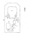
- the last setting mechanism 3 is disposed in the vicinity of the side of the carry-out belt conveyor 9.
- the article S since the article S is conveyed, while rotating in its inverted position, by the action of the carry-out belt conveyor 9, it has its whole circumference irradiated reliably with the ultraviolet ray which is emitted from the setting mechanism 3 disposed in the vicinity of the side of that belt conveyor 9.
- the outer circumferences of cylindrical articles having cylindrical circumferential walls can be multi-printed in precise registration with multiple colors. Since the ink applied is set before the subsequent printing process, the apparatus according to the present invention can completely exclude the disadvantage that the branket of the printer for the subsequent printing process is blotted with that ink in a different color, which has already been applied to the article S.
- ink in a different color can be additiona applied to the ink having already been applied, a completely composed color is enabled to appear thereby to freely exhibit a color of half tone and to remarkably reduce the number of the colors of ink to be used.
- the articles S are printed with these four colors in the order of the higher brightness, i.e., first the yellow ink, next the red ink, next the blue ink and finally the black ink.
- the present invention can enjoy the following many excellent advantages: that the multi-color printing processes can be accomplished smoothly without any mixing of the different colors of ink in the respective printers; that the printing registrations can be attained remarkably precisely and reliably with ease.; that the numerous articles S can be printed continuousl and uniformly; that the number of the colors to be used may be limited_notwithstanding that not only a color of half tone but also most colors are enabled to appear by the printing processes so that the number of the printers can be four at most to simplify the whole construction of the printing apparatus and to provide this apparatus at a reasonable price; and that the printing registrations are invariable, once they are set, setthat the subsequent printing processes can be automatically accomplished while ensuring the reliable registrations..
Landscapes
- Specific Conveyance Elements (AREA)
- Screen Printers (AREA)
- Printing Methods (AREA)
- Manufacture Or Reproduction Of Printing Formes (AREA)
- Inks, Pencil-Leads, Or Crayons (AREA)
Applications Claiming Priority (2)
| Application Number | Priority Date | Filing Date | Title |
|---|---|---|---|
| US06/360,838 US4479429A (en) | 1982-03-22 | 1982-03-22 | Multi-color printing apparatus of surfaces of bodies of rotation |
| US360838 | 1999-07-26 |
Publications (3)
| Publication Number | Publication Date |
|---|---|
| EP0089660A2 true EP0089660A2 (fr) | 1983-09-28 |
| EP0089660A3 EP0089660A3 (en) | 1985-05-22 |
| EP0089660B1 EP0089660B1 (fr) | 1988-06-08 |
Family
ID=23419602
Family Applications (1)
| Application Number | Title | Priority Date | Filing Date |
|---|---|---|---|
| EP83102778A Expired EP0089660B1 (fr) | 1982-03-22 | 1983-03-21 | Dispositif d'impression à couleurs multiples pour surfaces d'objets rotatifs |
Country Status (6)
| Country | Link |
|---|---|
| US (1) | US4479429A (fr) |
| EP (1) | EP0089660B1 (fr) |
| JP (1) | JPS58217358A (fr) |
| AU (1) | AU558916B2 (fr) |
| CA (1) | CA1188924A (fr) |
| DE (1) | DE3376967D1 (fr) |
Families Citing this family (16)
| Publication number | Priority date | Publication date | Assignee | Title |
|---|---|---|---|---|
| US4592276A (en) * | 1985-08-21 | 1986-06-03 | Dubuit Jean Louis M | Printing machine with curing system |
| JPH0363166A (ja) * | 1989-08-01 | 1991-03-19 | Hokoku Jushi Kogyo Kk | 印刷装置 |
| WO1997016075A1 (fr) | 1995-11-01 | 1997-05-09 | Wm. Wrigley Jr. Company | Procede et appareil d'impression sur des produits de confiserie |
| US6310957B1 (en) * | 1996-12-23 | 2001-10-30 | At&T Corp. | Method and apparatus for interdicting cable television channels |
| US6314876B1 (en) | 1999-06-07 | 2001-11-13 | Ackley Machine Corporation | Method and apparatus for transporting and processing a plurality of articles, and shaped article having serially registered component images |
| US6367384B1 (en) | 2000-02-29 | 2002-04-09 | Illusion Lures, Inc. | Process for applying 4 color image to a fishing lure |
| KR20030045524A (ko) * | 2001-12-04 | 2003-06-11 | 정승태 | 자동실크인쇄시스템 |
| JP5954791B2 (ja) * | 2010-01-22 | 2016-07-20 | サン ケミカル コーポレーション | エネルギー硬化型フレキソ印刷インク又は塗料のウェットトラッピング |
| BR102012016393A2 (pt) | 2012-07-02 | 2015-04-07 | Rexam Beverage Can South America S A | Dispositivo de impressão em latas, processo de impressão em latas, lata impressa e blanqueta |
| US9555616B2 (en) | 2013-06-11 | 2017-01-31 | Ball Corporation | Variable printing process using soft secondary plates and specialty inks |
| US10086602B2 (en) | 2014-11-10 | 2018-10-02 | Rexam Beverage Can South America | Method and apparatus for printing metallic beverage container bodies |
| PL3028856T3 (pl) | 2014-12-04 | 2019-10-31 | Ball Beverage Packaging Europe Ltd | Urządzenie drukujące |
| US10549921B2 (en) | 2016-05-19 | 2020-02-04 | Rexam Beverage Can Company | Beverage container body decorator inspection apparatus |
| US10976263B2 (en) | 2016-07-20 | 2021-04-13 | Ball Corporation | System and method for aligning an inker of a decorator |
| US11034145B2 (en) | 2016-07-20 | 2021-06-15 | Ball Corporation | System and method for monitoring and adjusting a decorator for containers |
| CN107915070A (zh) * | 2017-12-22 | 2018-04-17 | 深圳怡化电脑股份有限公司 | 一种介质打印设备 |
Family Cites Families (10)
| Publication number | Priority date | Publication date | Assignee | Title |
|---|---|---|---|---|
| US2484671A (en) * | 1944-05-02 | 1949-10-11 | Owens Illinois Glass Co | Silk screen stencil decorating machine |
| US3276356A (en) * | 1964-10-02 | 1966-10-04 | Monsanto Co | Methods and apparatus for handling and forming indicia on articles |
| FR1513389A (fr) * | 1966-11-30 | 1968-02-16 | Verreries Mecaniques | Machine à décorer en plusieurs couleurs |
| GB1316271A (en) * | 1969-05-13 | 1973-05-09 | Jackson Developments Ltd Max | Multi-colour printing machine for cylindrical and frusto-conical objects |
| GB1489746A (en) * | 1973-12-21 | 1977-10-26 | Chromax Ltd | Machine for printing on cylindrical or frusto-conical containers with ultra-violet-light-setting ink |
| US3960073A (en) * | 1975-03-10 | 1976-06-01 | American Can Company | Machine for decorating two-piece cans |
| US4035214A (en) * | 1975-07-21 | 1977-07-12 | American Can Company | Total image transfer process |
| DE2552171A1 (de) * | 1975-11-21 | 1977-06-02 | Kurt G Hinterkopf | Maschine zum insbesondere mehrfarbigen bedrucken von hohlkoerperartigen werkstuecken |
| JPS5677187A (en) * | 1979-11-29 | 1981-06-25 | Daiwa Can Co Ltd | Multicolor printing method of can barrel |
| JPS56120350A (en) * | 1980-02-28 | 1981-09-21 | Yakult Honsha Co Ltd | Continuous multicolor printer for tapered section circular body |
-
1982
- 1982-03-22 US US06/360,838 patent/US4479429A/en not_active Expired - Lifetime
-
1983
- 1983-03-09 AU AU12313/83A patent/AU558916B2/en not_active Ceased
- 1983-03-18 CA CA000423957A patent/CA1188924A/fr not_active Expired
- 1983-03-21 EP EP83102778A patent/EP0089660B1/fr not_active Expired
- 1983-03-21 DE DE8383102778T patent/DE3376967D1/de not_active Expired
- 1983-03-22 JP JP58047810A patent/JPS58217358A/ja active Granted
Also Published As
| Publication number | Publication date |
|---|---|
| JPS58217358A (ja) | 1983-12-17 |
| EP0089660A3 (en) | 1985-05-22 |
| JPH048227B2 (fr) | 1992-02-14 |
| EP0089660B1 (fr) | 1988-06-08 |
| CA1188924A (fr) | 1985-06-18 |
| AU558916B2 (en) | 1987-02-12 |
| US4479429A (en) | 1984-10-30 |
| AU1231383A (en) | 1983-09-29 |
| DE3376967D1 (en) | 1988-07-14 |
Similar Documents
| Publication | Publication Date | Title |
|---|---|---|
| EP0089660A2 (fr) | Dispositif d'impression à couleurs multiples pour surfaces d'objets rotatifs | |
| US5970865A (en) | Apparatus and method for printing multi-color images onto cylindrical body | |
| JP4435337B2 (ja) | 回動自在な被印刷体キャリヤ支持体を備えた印刷機 | |
| US3294016A (en) | Apparatus for printing on cylindrical containers | |
| US3960073A (en) | Machine for decorating two-piece cans | |
| JP4056561B2 (ja) | 瓶もしくは同等の物品に装飾を施すための方法及び装置 | |
| KR960012752B1 (ko) | 용기 이송 장치 및 그 방법 | |
| US3645201A (en) | Multicolor printing machine cylindrical and frustoconical objects | |
| WO1994000299A1 (fr) | Appareil de transport et de serrage pour presses offset a plusieurs couleurs | |
| US4455934A (en) | Color head for offset press | |
| US2009098A (en) | Apparatus for stenciling ware | |
| JPH07237745A (ja) | 異径容器用容器保持具 | |
| JPH0460022B2 (fr) | ||
| ATE172405T1 (de) | Mehrfarben-siebdruckmaschine für behälter mit gekrümmter oberfläche | |
| US3385209A (en) | Printing apparatus for cylindrical objects | |
| US7100507B1 (en) | Flexographic rotary platen printing press | |
| US6834588B2 (en) | Flexographic rotary platen printing press | |
| GB2203695A (en) | Turret machine for screen printing onto articles | |
| US3139817A (en) | Apparatus for marking articles | |
| US3103877A (en) | Printing machine | |
| US1033824A (en) | Multiple-color tube-printing machine. | |
| CA1113781A (fr) | Appareil a decorer | |
| JPH02175252A (ja) | 多色印刷機 | |
| JPH0640007A (ja) | 円筒体の多色連続印刷装置 | |
| JP2014201006A (ja) | 駆動伝達機構 |
Legal Events
| Date | Code | Title | Description |
|---|---|---|---|
| PUAI | Public reference made under article 153(3) epc to a published international application that has entered the european phase |
Free format text: ORIGINAL CODE: 0009012 |
|
| AK | Designated contracting states |
Designated state(s): CH DE FR GB IT LI NL |
|
| 17P | Request for examination filed |
Effective date: 19830927 |
|
| PUAL | Search report despatched |
Free format text: ORIGINAL CODE: 0009013 |
|
| AK | Designated contracting states |
Designated state(s): CH DE FR GB IT LI NL |
|
| RHK1 | Main classification (correction) |
Ipc: B41F 17/22 |
|
| 17Q | First examination report despatched |
Effective date: 19860526 |
|
| ITF | It: translation for a ep patent filed | ||
| GRAA | (expected) grant |
Free format text: ORIGINAL CODE: 0009210 |
|
| AK | Designated contracting states |
Kind code of ref document: B1 Designated state(s): CH DE FR GB IT LI NL |
|
| REF | Corresponds to: |
Ref document number: 3376967 Country of ref document: DE Date of ref document: 19880714 |
|
| ET | Fr: translation filed | ||
| PLBE | No opposition filed within time limit |
Free format text: ORIGINAL CODE: 0009261 |
|
| STAA | Information on the status of an ep patent application or granted ep patent |
Free format text: STATUS: NO OPPOSITION FILED WITHIN TIME LIMIT |
|
| 26N | No opposition filed | ||
| ITTA | It: last paid annual fee | ||
| PGFP | Annual fee paid to national office [announced via postgrant information from national office to epo] |
Ref country code: GB Payment date: 19970311 Year of fee payment: 15 |
|
| PGFP | Annual fee paid to national office [announced via postgrant information from national office to epo] |
Ref country code: FR Payment date: 19970319 Year of fee payment: 15 |
|
| PGFP | Annual fee paid to national office [announced via postgrant information from national office to epo] |
Ref country code: CH Payment date: 19970324 Year of fee payment: 15 |
|
| PGFP | Annual fee paid to national office [announced via postgrant information from national office to epo] |
Ref country code: NL Payment date: 19970331 Year of fee payment: 15 |
|
| PGFP | Annual fee paid to national office [announced via postgrant information from national office to epo] |
Ref country code: DE Payment date: 19970428 Year of fee payment: 15 |
|
| PG25 | Lapsed in a contracting state [announced via postgrant information from national office to epo] |
Ref country code: GB Free format text: LAPSE BECAUSE OF NON-PAYMENT OF DUE FEES Effective date: 19980321 |
|
| PG25 | Lapsed in a contracting state [announced via postgrant information from national office to epo] |
Ref country code: LI Free format text: LAPSE BECAUSE OF NON-PAYMENT OF DUE FEES Effective date: 19980331 Ref country code: FR Free format text: THE PATENT HAS BEEN ANNULLED BY A DECISION OF A NATIONAL AUTHORITY Effective date: 19980331 Ref country code: CH Free format text: LAPSE BECAUSE OF NON-PAYMENT OF DUE FEES Effective date: 19980331 |
|
| PG25 | Lapsed in a contracting state [announced via postgrant information from national office to epo] |
Ref country code: NL Free format text: LAPSE BECAUSE OF NON-PAYMENT OF DUE FEES Effective date: 19981001 |
|
| GBPC | Gb: european patent ceased through non-payment of renewal fee |
Effective date: 19980321 |
|
| REG | Reference to a national code |
Ref country code: CH Ref legal event code: PL |
|
| NLV4 | Nl: lapsed or anulled due to non-payment of the annual fee |
Effective date: 19981001 |
|
| PG25 | Lapsed in a contracting state [announced via postgrant information from national office to epo] |
Ref country code: DE Free format text: LAPSE BECAUSE OF NON-PAYMENT OF DUE FEES Effective date: 19981201 |
|
| REG | Reference to a national code |
Ref country code: FR Ref legal event code: ST |