EP0089677A1 - Kassenschalter - Google Patents
Kassenschalter Download PDFInfo
- Publication number
- EP0089677A1 EP0089677A1 EP83102832A EP83102832A EP0089677A1 EP 0089677 A1 EP0089677 A1 EP 0089677A1 EP 83102832 A EP83102832 A EP 83102832A EP 83102832 A EP83102832 A EP 83102832A EP 0089677 A1 EP0089677 A1 EP 0089677A1
- Authority
- EP
- European Patent Office
- Prior art keywords
- section
- passage
- cart
- receiving section
- counter
- Prior art date
- Legal status (The legal status is an assumption and is not a legal conclusion. Google has not performed a legal analysis and makes no representation as to the accuracy of the status listed.)
- Granted
Links
Images



Classifications
-
- A—HUMAN NECESSITIES
- A47—FURNITURE; DOMESTIC ARTICLES OR APPLIANCES; COFFEE MILLS; SPICE MILLS; SUCTION CLEANERS IN GENERAL
- A47F—SPECIAL FURNITURE, FITTINGS, OR ACCESSORIES FOR SHOPS, STOREHOUSES, BARS, RESTAURANTS OR THE LIKE; PAYING COUNTERS
- A47F9/00—Shop, bar, bank or like counters
- A47F9/02—Paying counters
- A47F9/04—Check-out counters, e.g. for self-service stores
- A47F9/045—Handling of baskets or shopping trolleys at check-out counters, e.g. unloading, checking
Definitions
- the invention relates to a counter system comprising at least one counter and a plurality of shopping carts, and wherein the counter includes a cashier's section as well as a conveyor band advancing the articles to said section, said counter co-operating in defining a passage, through which the carts are moved past the cashier's section.
- a counter system of this type is known, which is made of a plurality of parallel counters at regular intervals, whereby a passage is formed between each pair of counters.
- Each counter includes a cashier's section, and when moving along the passage with his shopping cart each customer can pay at the cashier's section in said passage.
- the object of the present invention is to provide a counter system of the above type, which in a very reliable manner prevents customers from passing the system with their articles without having paid for all said articles at the cashier's section.
- the counter system according to the invention is characterised in that the counter comprises a bracket-shaped receiving section, the distance of which from the floor on which the system is situated is only slightly greater, preferably a few millimetres such as 4 millimetres, than the distance from the surface of the freely accessible loading surface of the cart to the floor, and that the passage is of a width slightly smaller than the width of the shopping cart in such a manner that the shopping carts can only be pushed forward manually in said passage when they are positioned perpendicular to the receiving section and their loading surface simultaneously extends below said section, whereby the receiving section removes the articles, if any, present on the loading surface of the cart when said cart passes the system.
- the counter system is particularly suitable for great voluminous articles because the loading surface of the shopping cart may comprise a great low loading surface for the transport of the articles.
- the system requires no extra employees compared to the known systems.
- the access end of the receiving section may according to the invention be positioned perpendicular to the longitudinal direction of the passage, whereby the receiving section in a particularly efficient manner is capable of brushing off the articles from the loading surface of the cart, when said cart is pushed below the receiving section.
- the access end of the receiving section may be rectilinear and form an obtuse angle with the longitudinal direction of the passage.
- the conveyor may be in two parts. This embodiment of the system is particularly advantageous when the access end of the receiving section as previously mentioned forms an abtuse angle with the longitudinal direction of the passage.
- the receiving section projects a distance greater than or equal to half the length of each shopping cart, said distance being measured in a direction perpendicular to the longitudinal direction of the passage, and a preferably adjustable auxiliary section is provided on the receiving section adjacent or on the access end thereof, said auxiliary section narrowing the passage locally and projecting transversely into said passage, whereby the auxiliary section is positioned a short distance above the surface of the loading surface of the cart and projecting so far into the passage that the receiving section plus the auxiliary section are capable of brushing off substantially the entire loading surface of the cart when said cart is transversely positioned and pushed forward in the passage.
- a preferably adjustable auxiliary section is provided on the receiving section adjacent or on the access end thereof, said auxiliary section narrowing the passage locally and projecting transversely into said passage, whereby the auxiliary section is positioned a short distance above the surface of the loading surface of the cart and projecting so far into the passage that the receiving section plus the auxiliary section are capable of brushing off substantially the entire loading surface of the cart when said cart is
- the access end of the receiving section may according to the invention be provided with a preferably adjustable brushing off means such as a brushing off plate or hoop, which is optionally slightly resilient and optionally extends so far that it can brush off the loading surface of the cart.
- a preferably adjustable brushing off means such as a brushing off plate or hoop, which is optionally slightly resilient and optionally extends so far that it can brush off the loading surface of the cart.
- the receiving section may along the passage be provided with a removable strip such as a metal strip.
- a removable strip such as a metal strip.
- a brushing off member such as a strip or a brush may be provided inside or below the receiving section opposite the cashier's section, said member optionally being obliquely mounted and preferably of the rotating type for brushing off thin articles from the loading surface of the cart and for carrying said articles to the cashier's section.
- very thin articles e.g. of paper or fabric
- the cashier can settle these particular articles too.
- the conveyor band can extend obliquely upwards on the receiving section from the access end thereof,and that the conveyor band is optionally angularly adjustable.
- the customer need only move the article a short distance at the brushing off of the article from the loading surface of the cart, viz. from said loading surface of the cart and a few centimetres upwards to the beginning of the conveyor band.
- the conveyor band advances the article obliquely upwards to the cashier's section. It is an advantage when the angle of inclination of the conveyor band is adjustable, since the conveyor band then is adjustable to the articles to be paid for. When it for instance is a question of very heavy articles, the angle of inclination is made relatively small.
- the conveyor band may be defined by preferably high guide walls situated laterally, the side walls for instance being solid or shaped as hoops, whereby the articles advanced on the conveyor band do not fall off said band easily.
- a guide or catching means preferably a rail, may be provided in the spacing below the receiving section, said rail ensuring that each cart is maintained substantially perpendicular to the longitudinal direction of the passage during their movement past the cashier's section.
- the guide or catching means may comprise a carting-in section preferably of a small radius of curvature adjacent the access end of the receiving section, said carting-in section guiding or catching the end or wheel of the shopping carts at the initial moving of the loading surface of the cart below the receiving section.
- the cart slides into the correct position relative to the receiving section as soon as the customer reaches the access end of the receiving section.
- the cart maintains this correct position, i.e. perpendicular to the receiving section, during the entire passing through the passage.
- the guide or catching means may on or adjacent the place of the shopping cart is to be removed from the counter comprise a carting-out section, which for instance may be rectilinear and form an obtuse angle with the remaining portion of the guide or catching means or be curved, preferably along a circular arc of a great radius of curvature.
- the receiving section may opposite the cashier's section or slightly spaced therefrom include an end area optionally provided with plastic rollers collecting the articles to be cashed as well as optionally a second collecting end area for articles already cashed (seen in the advancing direction of the conveyor band).
- an end area optionally provided with plastic rollers collecting the articles to be cashed as well as optionally a second collecting end area for articles already cashed (seen in the advancing direction of the conveyor band).
- a sufficient room is provided for the articles to be paid for or which have already been paid for.
- the articles already paid for and present at the part of the counter opposite the receiving section balance the counter in such a manner that they balance relative to the articles present on the projecting receiving section.
- each cart may according to a sectional longitudinal view be substantially L-shaped and at the upper end of the L optionally provided with a relatively small shopping basket, a handle being provided at said upper end of the L, whereby each shopping cart is easy to handle.
- the passage may be defined to one side by the projecting side of the receiving section of a counter and to the other side by the back of a neighboring counter and/or a a substantially planar defining portion such as a wall or a rail immediately associated therewith.
- the passage is provided in a particularly simple manner.
- the auxiliary section narrowing the passage may be shaped as a hoop section extending from one of the guide walls along the conveyor band, said hoop section preferably projecting such a length that it permits exactly passage of the upper part of the shopping cart when the cart is positioned perpendicular to the long side of the receiving section.
- anchoring means for securing the counter to the floor are provided at the end of said counter which is farthest from the receiving section. In this manner the receiving section cannot be pressed downwards against the floor even at transport and settling of very heavy articles on the counter since the counter tilts.
- a mirror for an additional control by the cashier of the loading surface of a passing cart is provided in the passage in a position opposite the cashier's section to allow the cashier to ensure that the loading surface is empty.
- the cashier can watch the part of the loading surface that projects outside the receiving section, whereby the cashier discovers quickly the articles, if any, that are tried to be smuggled out on the cart.
- the passage may according to the invention be defined to one side by the projecting side surface of the receiving section and to the other side by a vertical wall portion or railing extending parallel to the receiving section.
- This embodiment of the system is particularly simple.
- a dividing member substantially as high as the hips such as a wall portion or a rail is mounted longitudinally in the passage, said dividing member guiding the carts at the end of the carts where said carts are provided with a handle.
- the counter system illustrated in Fig. 9 comprises two counters 1 and a plurality of shopping carts 2.
- Each counter 1 includes a cashier's section 3, where an employee can sit at his cash register and cash the articles of the customers as said articles pass.
- Each counter 1 comprises a conveyor band 5 advancing the articles from the access end 7 of the counter to the cashier's section.
- a spacing is present between the two counters 1, said spacing forming a passage 9 permitting a forward passing of the carts.
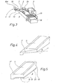
- Each counter is as illustrated in Figs. 2 and 3 provided with a bracket-shaped receiving section 10, the distance a of which from the floor on which the system is positioned is only slightly greater than the distance b from the surface 12a of the loading surface 12 of the cart to the floor.
- the passage 9 is of a width c smaller than the width d of each shopping cart, cf. Fig. 1. Therefore each shopping cart can only be pushed forward manually in the passage 9 when they are positioned perpendicular to the receiving section 3 and their loading surfaces 12 simultaneously project below said receiving section. However, during such a pushing forward, the receiving section 3 brushes off the article(s) 15, if any, present on the loading surface 12. During this brushing off, the customer must catch the-article and place it on the conveyor band in such a manner that it is advanced to the cashier's section for payment.
- the loading surface of the cart is freely accessible, i.e. at three edges it is free of side-restricting parts.
- Figs. 1 and 2 illustrate how the access end 7 forms a surface perpendicular to the longitudinal direction of the passage 9, as indicated at the arrow A.
- the access end of the receiving section of the counter may be obliquely cut and thereby form an obtuse angle a with the longitudinal direction of the passage, cf. the arrow B.
- the conveyor band 5 may optionally be in two parts, e.g. in such a manner that the two conveyor parts form an angle with each other. This embodiment is, however, not illustrated in the drawing.
- the receiving section 10 projects a distance greater than half the length of each shopping cart, said distance being measured in a direction perpendicular to the longitudinal direction of the passage, i.e. greater than half the length of the loading surface 12.
- the re- ceivin g section 10 is adjacent its access end 7" provided with a preferably adjustable auxiliary section 16 projecting transversely into the passage and narrowing said passage locally.
- This auxiliary section is preferably adjustable in height and is positioned slightly higher than the surface 12a of the loading surface of the cart.
- this auxiliary section projects so far into the passage that the receiving section 10 plus the auxiliary section 16 may brush off substantially the entire loading surface 12 of the cart when the transversely positioned cart as shown is pushed forward in the passage.
- the narrowed portion is of a width of about 50 centimetres. Then the customer realizes quickly that he cannot pass with a filled cart and that the cart must be turned for further advancing.
- Fig. 5 illustrates a particular embodiment of the receiving section 10'.
- the access end 7"' of this embodiment is provided with a brushing off means 18 in the form of a brushing off plate.
- This plate may optionally be slightly resilient and optionally extend so far that it can scrape across the surface 12a of the loading surface 12 of the cart, cf. Fig. 2.
- the plate may project a short distance downwards as indicated to the left at 7a of Fig. 9.
- the brushing off plate 18 When the brushing off plate 18 is resilient, it may be provided with a row of notches 19 in such a manner that a sort of tongues are formed.
- Fig. 5 illustrates how the receiving section 10' along the passage 9 may comprise a removable strip 20, e.g. of metal.
- This strip permits a quick ex- trication of the loading surface of the cart, if said cart should be squeezed below the receiving section because a thin article is clamped between the loading surface and the receiving section.
- Fig. 7 illustrates how a brushing off member for instance in the form of a strip or a brush may be mounted within the receiving section 10', seen from the back, viz. the cashier's section.
- the member is a brush 22 of the rotating type.
- the brush or strip may optionally be inclined.
- the strip or brush serve to brush off thin articles, if any, present on the loading surface 12 of the cart in spite of the brushing off procedure at the access end 7"" of the receiving section.
- Fig. 7 illustrates clearly how the conveyor band 5 may extend obliquely upwards on the receiving section 10' from the access end 7"" of the latter.
- the conveyor band 5 may optionally be adapted in such a manner that its angle with the horizontal plane is adjustable.
- Fig. 3 illustrates how the conveyor band 5 may be defined by preferably high guide walls 24 situated aside and for instance being solid or shaped as hoops.
- F ig. 3 illustrates hoop-shaped guide walls, and the spacings inside the hoops may optionally be filled with a plastic material so that great rigid walls are formed.
- the side walls 24 serve to support the articles to be transported from the access end 7 of the receiving section 10 to the cashier's section.
- the guide walls 24 are of particular importance when the article to be transported upwards by the conveyor band 5 is of a width greater than the width of the conveyor so that the article must be transported upwards in an angular position, one end of the article supporting on the band 5 and the opposite end of said article sliding on one of the guide walls 24.
- FIG. 8 illustrates a further embodiment of a counter according to the invention.
- a guide or catching means is as indicated by the dotted lines 25 mounted in the spacing between the receiving section 10 of this counter and the floor, and this guide or catching means may be formed as a rail.
- This rail forms a contact surface at the end of each loading surface 12 of the cart in such a manner that the cart can be maintained in a substantially perpendicular position relative to the longitudinal direction of the passage, cf. the arrow A, during the passing of the cart past the cashier's section 3.
- the rail 25 may either be suspended from the receiving section 10 or project from the floor below the receiving section.
- the guide and catching means 25 is formed by a longitudinal groove in the floor below the receiving section, and then the wheels of each cart 2 follows the groove. Two parallel grooves are preferably provided corresponding to the two pairs of wheels of the cart.
- the guide and catching means 25 may at the access end 7a of the receiving section 10 be provided with a carting-in section 26 guiding or catching the end or wheels of the shopping cart at the entering of the loading surface 12 of the cart below the receiving section 10.
- the carting-in section 26 is also a rail optionally of a small radius of curvature.
- the guide or catching means 25 may comprise a carting-out section 27, which is curved, cf. Fig. 8. It may optionally be circularly curved, the radius of curvature being relatively great.
- the carting-out section may, however, also be rectilinear, cf. the dotted line at 27 in Fig. 1, and then it forms an ahtuse angle with the remaining part of the guide or catching means.
- Figs. 3 and 8 illustrate how an end area 29 may be provided on the receiving section 10 opposite the cashier's section 3 or slightly spaced therefrom.
- This end area 29 is optionally provided with plastic rollers and serve to collect the articles to be paid for at the cashier.
- a second collecting end area 30 collecting articles already paid for may be provided immediately adjacent the above collecting end area 29.
- the articles on the end area 30 co-operate in balancing the counter, said articles often being relatively heavy. This is due to the fact that these articles prevent the projecting receiving section 10 from tilting downwards towards the floor when it is subjected to a very great vertical load for instance deriving from very heavy articles.
- Fig. 2 is a longitudinal sectional view of each cart showing that each cart is substantially L-shaped. At the upper end of the L, a handle 42 is present and adjacent this handle, a relatively small shopping basket optionally demountable is mounted.
- Fig. 10 illustrates how the passage 9 may be defined to one side by the projecting side 10a of the receiving section 10 of one counter and to the other side by the back of a neighboring counter and/or by a substantially planar defining portion 32 in the form of for instance a wall or a railing immediately associated therewith.
- the connection is usually carried out at the wall in the cashier's section 3". Bargain articles and the like may, if desired, be displayed in the areas indicated by the crosses 34 in Figs. 1 and 10, which, however, is irrelevant in connection with the present invention.
- the auxiliary section narrowing the passage 9 may be shaped as a hoop member 16a projecting from the guide wall 24 adjacent the passage 9.
- the hoop member 16a projects preferably so far into the passage 9 that it permits exactly passing of the upper part of the shopping cart into the passage when the cart is positioned perpendicular to the long side of the receiving section 10'.
- anchoring means 40 securing the counter to the floor may be mounted at the end of the counter which is farthest from the receiving section 10, i.e. at the outermost right end of the counter. In this manner a great security of the counter not tilting is obtained when the receiving section 10 is loaded by very heavy articles.
- a mirror 45 may be mounted in the passage 9 opposite the cashier's section 3. This mirror provides the employee with an extra control that the loading surface of a passing cart is in fact empty, since the employee can watch the part of the loading surface of the cart not covered by the receiving section 10 by means of said mirror.
- Fig. 12 illustrates a system including only one counter 1".
- the passage 9 of the system is defined to one side by the projecting side l0a" of the receiving section 10" and to the other side by a vertical wall portion 32" which is parallel to the receiving section 10".
- Fig. 13 illustrates a system corresponding to the system of Fig. 12. However, in Fig. 13 the passage is divided into two halves 9a and 9b by means of a longitudinal dividing member 36 preferably as high as the hips.
- This dividing member may be formed by a wall portion or a railing and serves to guide the carts 2 at the end where they are provided with a handle while the carts are pushed through the system.
- the invention may be varied in many ways without deviating from the scope of the invention.
- the system may include a very high number of counters, e. g . 10-12 counters.
- An advantage of all the embodiments of the system is that the customers must pay for all the articles on the carts before they leave the system and consequently the shop having installed the system.
Landscapes
- Handcart (AREA)
- Exchange Systems With Centralized Control (AREA)
- Selective Calling Equipment (AREA)
- Preparation Of Compounds By Using Micro-Organisms (AREA)
- Channel Selection Circuits, Automatic Tuning Circuits (AREA)
- Control Of Multiple Motors (AREA)
Priority Applications (1)
| Application Number | Priority Date | Filing Date | Title |
|---|---|---|---|
| AT83102832T ATE16974T1 (de) | 1982-03-22 | 1983-03-22 | Kassenschalter. |
Applications Claiming Priority (2)
| Application Number | Priority Date | Filing Date | Title |
|---|---|---|---|
| DK1285/82 | 1982-03-22 | ||
| DK128582A DK148465C (da) | 1982-03-22 | 1982-03-22 | Kassedisk-anlaeg |
Publications (2)
| Publication Number | Publication Date |
|---|---|
| EP0089677A1 true EP0089677A1 (de) | 1983-09-28 |
| EP0089677B1 EP0089677B1 (de) | 1985-12-18 |
Family
ID=8103121
Family Applications (1)
| Application Number | Title | Priority Date | Filing Date |
|---|---|---|---|
| EP83102832A Expired EP0089677B1 (de) | 1982-03-22 | 1983-03-22 | Kassenschalter |
Country Status (6)
| Country | Link |
|---|---|
| US (1) | US4548295A (de) |
| EP (1) | EP0089677B1 (de) |
| AT (1) | ATE16974T1 (de) |
| CA (1) | CA1228567A (de) |
| DE (1) | DE3361530D1 (de) |
| DK (1) | DK148465C (de) |
Cited By (1)
| Publication number | Priority date | Publication date | Assignee | Title |
|---|---|---|---|---|
| EP0136525A3 (en) * | 1983-09-06 | 1987-01-14 | Sb-Handels Ag Metro | Paying counter for self-service stores |
Families Citing this family (3)
| Publication number | Priority date | Publication date | Assignee | Title |
|---|---|---|---|---|
| US6201473B1 (en) | 1999-04-23 | 2001-03-13 | Sensormatic Electronics Corporation | Surveillance system for observing shopping carts |
| US20050183402A1 (en) * | 2004-02-25 | 2005-08-25 | Ball James A. | Grocery bagging and transfer apparatus |
| USD976626S1 (en) * | 2020-02-06 | 2023-01-31 | Hanwha Techwin Co., Ltd. | Checkout stand |
Citations (2)
| Publication number | Priority date | Publication date | Assignee | Title |
|---|---|---|---|---|
| FR1394756A (fr) * | 1962-11-13 | 1965-04-09 | Dispositif pour poste de facturation dans les magasins du type <libre-service> ou autres du même genre | |
| US3739878A (en) * | 1971-05-18 | 1973-06-19 | W Jay | Grocery cart and checkout counter combination |
Family Cites Families (5)
| Publication number | Priority date | Publication date | Assignee | Title |
|---|---|---|---|---|
| US2368986A (en) * | 1942-07-10 | 1945-02-06 | Toledo Scale Co | Weighing scale |
| US3517773A (en) * | 1968-06-18 | 1970-06-30 | Russell K Swanson | Check-out system and counter for use with cantilever shopping cart |
| US4007809A (en) * | 1975-08-27 | 1977-02-15 | Bag System Ab | System for handling goods in selfservice shops |
| US4298099A (en) * | 1978-05-12 | 1981-11-03 | Harold Isaacs | Merchandise order picking system and work table |
| US4327819A (en) * | 1980-08-01 | 1982-05-04 | Coutta John M | Object detection system for a shopping cart |
-
1982
- 1982-03-22 DK DK128582A patent/DK148465C/da not_active IP Right Cessation
-
1983
- 1983-03-21 US US06/477,075 patent/US4548295A/en not_active Expired - Lifetime
- 1983-03-21 CA CA000424070A patent/CA1228567A/en not_active Expired
- 1983-03-22 EP EP83102832A patent/EP0089677B1/de not_active Expired
- 1983-03-22 AT AT83102832T patent/ATE16974T1/de active
- 1983-03-22 DE DE8383102832T patent/DE3361530D1/de not_active Expired
Patent Citations (2)
| Publication number | Priority date | Publication date | Assignee | Title |
|---|---|---|---|---|
| FR1394756A (fr) * | 1962-11-13 | 1965-04-09 | Dispositif pour poste de facturation dans les magasins du type <libre-service> ou autres du même genre | |
| US3739878A (en) * | 1971-05-18 | 1973-06-19 | W Jay | Grocery cart and checkout counter combination |
Cited By (1)
| Publication number | Priority date | Publication date | Assignee | Title |
|---|---|---|---|---|
| EP0136525A3 (en) * | 1983-09-06 | 1987-01-14 | Sb-Handels Ag Metro | Paying counter for self-service stores |
Also Published As
| Publication number | Publication date |
|---|---|
| CA1228567A (en) | 1987-10-27 |
| ATE16974T1 (de) | 1986-01-15 |
| DK148465C (da) | 1985-12-16 |
| DE3361530D1 (en) | 1986-01-30 |
| US4548295A (en) | 1985-10-22 |
| DK148465B (da) | 1985-07-15 |
| EP0089677B1 (de) | 1985-12-18 |
| DK128582A (da) | 1983-09-23 |
Similar Documents
| Publication | Publication Date | Title |
|---|---|---|
| CA1308134C (en) | Shopping trolley provided with a pivoting basket | |
| US4450968A (en) | Nestable cart anti-reversing apparatus | |
| US4373611A (en) | Conveyor to interfit with a loaded shopping cart and to move portions of the load, on demand of a checker, to the front of the cart, for removal, price scanning, and bagging, by the checker at a checkout stand | |
| EP0776308A1 (de) | Verfahren und einrichtung zum kommissionieren | |
| EP0089677B1 (de) | Kassenschalter | |
| DE2028144A1 (de) | Abfertigungstischsystem für Selbstbedienungsladen | |
| US5360094A (en) | Collection, storage and dispensing system for shopping carts | |
| US5027924A (en) | Cashier check-out station with package-catching shopping cart | |
| US4465313A (en) | Installation for storing and transporting elongated objects | |
| US5529163A (en) | Collection, storage and dispensing system and vertical lift for shopping carts | |
| JPH0455694B2 (de) | ||
| SE8202598L (sv) | Sett att underletta hantering och transport av artiklar i snabbkopsvagnar, samt anordning och vagn for utovande av settet | |
| US3739878A (en) | Grocery cart and checkout counter combination | |
| EP1693318B1 (de) | Einkaufswagen und Behältersystem | |
| US3083978A (en) | Cart having a removable load carrier | |
| DE9007133U1 (de) | Einkaufskorbset | |
| US2766049A (en) | Nesting shopping cart | |
| CH401704A (de) | Einrichtung mit fahrbaren, stapelbaren Warenkörben und mit Kassentisch für Selbstbedienungsläden | |
| GB1595691A (en) | Trolley | |
| DE69900759T2 (de) | Handhabungssystem für artikel im einzelhandel des kaufhauses | |
| EP0449248A1 (de) | Verfahren zum Einkaufen von Ware in Selbstbedienungsgeschäften | |
| US2603315A (en) | Self-service system for salesrooms of stores | |
| DE2015148C3 (de) | Warenabrechnungseinrichtung für Selbstbedienungsläden | |
| JP2717351B2 (ja) | 物品仕分機における仕分シュート装置 | |
| JPS6135272Y2 (de) |
Legal Events
| Date | Code | Title | Description |
|---|---|---|---|
| PUAI | Public reference made under article 153(3) epc to a published international application that has entered the european phase |
Free format text: ORIGINAL CODE: 0009012 |
|
| AK | Designated contracting states |
Designated state(s): AT CH DE FR GB LI SE |
|
| 17P | Request for examination filed |
Effective date: 19840213 |
|
| GRAA | (expected) grant |
Free format text: ORIGINAL CODE: 0009210 |
|
| AK | Designated contracting states |
Designated state(s): AT CH DE FR GB LI SE |
|
| REF | Corresponds to: |
Ref document number: 16974 Country of ref document: AT Date of ref document: 19860115 Kind code of ref document: T |
|
| REF | Corresponds to: |
Ref document number: 3361530 Country of ref document: DE Date of ref document: 19860130 |
|
| ET | Fr: translation filed | ||
| PLBE | No opposition filed within time limit |
Free format text: ORIGINAL CODE: 0009261 |
|
| STAA | Information on the status of an ep patent application or granted ep patent |
Free format text: STATUS: NO OPPOSITION FILED WITHIN TIME LIMIT |
|
| 26N | No opposition filed | ||
| REG | Reference to a national code |
Ref country code: CH Ref legal event code: PUE Owner name: INTER IKEA SYSTEMS B.V. |
|
| REG | Reference to a national code |
Ref country code: GB Ref legal event code: 732 |
|
| REG | Reference to a national code |
Ref country code: FR Ref legal event code: TP |
|
| REG | Reference to a national code |
Ref country code: FR Ref legal event code: ST |
|
| EAL | Se: european patent in force in sweden |
Ref document number: 83102832.9 |
|
| PGFP | Annual fee paid to national office [announced via postgrant information from national office to epo] |
Ref country code: SE Payment date: 19970312 Year of fee payment: 15 |
|
| PGFP | Annual fee paid to national office [announced via postgrant information from national office to epo] |
Ref country code: GB Payment date: 19970313 Year of fee payment: 15 |
|
| PGFP | Annual fee paid to national office [announced via postgrant information from national office to epo] |
Ref country code: FR Payment date: 19970320 Year of fee payment: 15 Ref country code: CH Payment date: 19970320 Year of fee payment: 15 |
|
| PGFP | Annual fee paid to national office [announced via postgrant information from national office to epo] |
Ref country code: AT Payment date: 19970326 Year of fee payment: 15 |
|
| PGFP | Annual fee paid to national office [announced via postgrant information from national office to epo] |
Ref country code: DE Payment date: 19970411 Year of fee payment: 15 |
|
| PG25 | Lapsed in a contracting state [announced via postgrant information from national office to epo] |
Ref country code: GB Free format text: LAPSE BECAUSE OF NON-PAYMENT OF DUE FEES Effective date: 19980322 Ref country code: AT Free format text: LAPSE BECAUSE OF NON-PAYMENT OF DUE FEES Effective date: 19980322 |
|
| PG25 | Lapsed in a contracting state [announced via postgrant information from national office to epo] |
Ref country code: SE Free format text: LAPSE BECAUSE OF NON-PAYMENT OF DUE FEES Effective date: 19980323 |
|
| PG25 | Lapsed in a contracting state [announced via postgrant information from national office to epo] |
Ref country code: LI Free format text: LAPSE BECAUSE OF NON-PAYMENT OF DUE FEES Effective date: 19980331 Ref country code: FR Free format text: THE PATENT HAS BEEN ANNULLED BY A DECISION OF A NATIONAL AUTHORITY Effective date: 19980331 Ref country code: CH Free format text: LAPSE BECAUSE OF NON-PAYMENT OF DUE FEES Effective date: 19980331 |
|
| GBPC | Gb: european patent ceased through non-payment of renewal fee |
Effective date: 19980322 |
|
| REG | Reference to a national code |
Ref country code: CH Ref legal event code: PL |
|
| PG25 | Lapsed in a contracting state [announced via postgrant information from national office to epo] |
Ref country code: DE Free format text: LAPSE BECAUSE OF NON-PAYMENT OF DUE FEES Effective date: 19981201 |
|
| EUG | Se: european patent has lapsed |
Ref document number: 83102832.9 |
|
| REG | Reference to a national code |
Ref country code: FR Ref legal event code: ST |