EP0089729A2 - Ancre à bras repliables - Google Patents
Ancre à bras repliables Download PDFInfo
- Publication number
- EP0089729A2 EP0089729A2 EP83200387A EP83200387A EP0089729A2 EP 0089729 A2 EP0089729 A2 EP 0089729A2 EP 83200387 A EP83200387 A EP 83200387A EP 83200387 A EP83200387 A EP 83200387A EP 0089729 A2 EP0089729 A2 EP 0089729A2
- Authority
- EP
- European Patent Office
- Prior art keywords
- anchor
- stem
- self
- arm
- forward end
- Prior art date
- Legal status (The legal status is an assumption and is not a legal conclusion. Google has not performed a legal analysis and makes no representation as to the accuracy of the status listed.)
- Granted
Links
Images


Classifications
-
- B—PERFORMING OPERATIONS; TRANSPORTING
- B63—SHIPS OR OTHER WATERBORNE VESSELS; RELATED EQUIPMENT
- B63B—SHIPS OR OTHER WATERBORNE VESSELS; EQUIPMENT FOR SHIPPING
- B63B21/00—Tying-up; Shifting, towing, or pushing equipment; Anchoring
- B63B21/24—Anchors
- B63B21/243—Anchors foldable or capable of being disassembled
Definitions
- This invention relates to a novel anchor having collapsible arms, for ships, boats and other watercraft.
- the present invention relates to a self-clearing anchor having arms which are movable relative to the stock and pivoted at the stock end or top and adapted to be collapsed whenever subjected to a sufficient stress, beyond the anchor top.
- the most common anchors are composed of a stock equipped at either end with fixed arms bent towards said stock and each fitted endwise with a fluke which holds at the sea bed and serves to moor the ship.
- Anchors are also known which have arms hingedly connected to the stock and which are collapsed when not in use so as to reduce the stowage bulk.
- said anchors exhibit outstretched spokes, like an umbrella, and these spokes are latched in their outstretched positions by a latching ring which is slipped about the anchor stock and can slide therealong.
- Seamen and sea sportsmen are right well aware of the difficulties which are often met with when heaving a foul anehor, especially when an anchor is caught by a rocky sea bed or by seaweed banks.
- an anchor buoy consisting of a buoy rope and a buoy at the rope end which is tied to the anchor top or the anchor crown so as to trip a foul anchor easily.
- An objective of the present invention is to provide an anchor which is susceptible to being easily cleared of the sea bottom irrespective of any kind of sea bed and without requiring manipulations or time waste.
- Another objective of the present invention is to provide an anchor having a self-clearing action which can be adjusted consistently with the size of the watercraft concerned, the kind of sea bed and the conditions of the sea, wind or marine currents obtaining in the mooring place.
- An advantage of the present invention is to have eliminated the hazard of losing an anchor when fouled.
- Another advantage of the present invention is the rapidity in heaving a foul anchor.
- the present invention is embodied by a self-clearing anchor which is character ized in that it exhibits one or more arms hinged to the stock in the vicinity of the anchor crown and cooperating with biassing means to counteract the rotation of said arms, the latter being capable of being collapsed beyond the anchor crown when subjected to a determined stress.
- said biassing means are adjustable and are fitted with appropriate regulation means.
- an anchor 10, according to the invention, displays a hollow stem 11 having at its forward end 111 an anchor ring 12 for connection to an anchor rope or an anchor chain, and one or more swingable arms 13 hinged each at 14 into a fork 15 which projects outside the stem 11 in the vicinity of the front end or crown 112.
- the hollow stem 11 has, at the end 112 and beneath and centrally relative to the prongs of the fork 15, a longitudinal slot 16 having a width wider that the width of the arm 13.
- the slot 16 is terminated by an abutment surface 116.
- the length of the slot 16 can be selected so that the abutment surface 116 offers always an abutment stop for the front end 113 of the arm 13, the latter being swingable about the pin 14, when in the position shown in phantom in Figure 1.
- biassing means 17 are provided to counteract the swing of the arms 13.
- said biassing means 17 for counteracting the swinging motion of the arms 13 consist of a helical compression spring 117.
- the compression spring 117 cooperates with a -body 18 slidably mounted internally of the stem 11 in correspondence with the slots 16 and partially jutting out of the front end 112 of the stem.
- An internal ledge 101 provided in the front end l12 of the stem prevents the slidable body 18 from being slipped outwards.
- the slidable body 18 cooperates with the front ends 113 of the arms 13.
- the end 113 of the arms 13 are shaped and have, with advantage, a spherical outline and are received in a seating 218 formed in the front section of the slidable body 18.
- the rear ends 213 of the arms 13 carry the anchor flukes.
- the seats 218 prevent the ends 113 of the arms 13 from being separated from the slidable body 18: as a matter of fact, by virtue of the abutting surfaces 318 and 418 of the seat 218, the end 113 of the arm 13 concerned is urged, without exiting the seating, in either direction consistently with the direction of motion of the slidable body 18.
- the arms 13 can always lie in the equilibrium position which is determined by the foremost position of the slidable body 18.
- the bias of the spring 117 In order for the arms 13 to be collapsed so as to clear the anchor when the latter is foul, the bias of the spring 117 must be overcome by pulling the anchor rope either by hand or with the aid of the boat or the ship engines, the engines being run ahead or astern as the case may be.
- the preload of the biassing means 17 for counteracting the swinging motion of the arms 13, that is to say, the spring 117, is adjusted by appropriate regulation means 19.
- These means 19 consist, in the example shown herein, of an externally screw-threaded ferrule 119 which is screwably engaged by the partially tapped interior of the rear section 111 of the stem 11.
- Ferrule 119 has, advantageously, an external nut 219 which serves for rotating the ferrule with the aid of a socket wrench or any appropriate equivalent means.
- the slidable body 18 may have an external flange 20 shown in Figure lA, having a stalk 120 which is external ly screw-threaded and is adapted to be screwed into a longitudinal tapped hole 118 formed through the slidable body 18.
- the flange 20 may have a projection 220 to be seized by an appropriate tool to have the flange rotated.
- the internal surface of the flange 20, indicated at 318, cooperates with the forward ends 113 of the arms 13, thus causing the ends 113 to cooperate with the sliding body 18 at any time, because, in this case, the seat 218, whereby the forward ends 113 of the arms 13 are restrained, is length adjustable so as to make possible a certain adjustment of the radial orientation of the arms 13. If the flange 20 is totally removed, the anchor can be stowed with its arms wholly collapsed.
- the flange 20 can be tied to the anchor by a chain so as to prevent the flange from going astray during stowage.
- the anchor according to this invention can be fitted with latching means 21 shown by way of example in Figure 1.
- Such latching means 21 consist of a latching pin 121 which can be slipped transversally of the stem 11, so as to be passed through the wall of the stem 11 and through the slidable body 18: the latter has, formed therethrough, a transversal bore 221 formed in registry with a bore 321 drilled through the stem 11.
- the latching pin 121 can be attached to the anchor by a chain connected to the ring 421 so as to prevent the pin from being lost.
- Figures 1B and 1C swhow an alternative embodiment of the slidable body 18, in which the ends 113 of the arms 13 are positively connected to said body 18.
- the slidable body 18 has on its forward section a stepped portion 22 having, in correspondence with each slot 16 formed on the stem, a fork 23 which cooperates with the forward spherical or rounded end 113 of its attendant arm 13 swingable about its own pin 14.
- the fork 23 has a guiding groove 123 which is transversally oriented.
- each arm 13 is provided, at least on a side in the vicinity of the edge, with a side projection 223 which is extended into said groove 123.
- the size and the shape of the groove 123 are so selected as not to disturb the collapse of the relative arm 13.
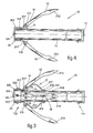
- the stem 11 is not necessarily hollowed out, but is equally fitted with forks 15 to which are pivoted, at 14, the arms 13 having their front ends 113 radiussed or spherically shaped.
- said forward ends 113 coact with biassing means 17 to counter act the rotation movements, said means consisting, each, in the example shown herein, of a leaf spring 217 having an end 317 secured and 319 to the outer surface of the stem 11'and rearwardly relative to the forks 15, and to the forward end 417 freely slidable longitudinally of the st,em in a guideway 517 which has been previously formed before the forks 15.
- the guideway 517 has an annular outline and is extended longitudinally towards the forks 15.
- Such guideway 517 might also be dispensed with: if so, the front ends 417 of the springs can be fastened to the stem 11 by set screws 321.
- the leaf spring forms a bend having its peak arranged past the pins 14 of the arms 13.
- the spherical ends 113 and a portion of the lower edges 313 of the arms always coact with the planar surface of the leaf spring 217 so that the arms 13 are compelled to take an always open equilibrium position as a result of the outline of the leaf spring 217.
- the longitudinal guideways 517 can be provided by securing to the forward end of the stem 11, for example, a cup shaped sleeve 21 having an inside diameter wider than the outside diameter of the stem 11.
- Such sleeve 21 is secured to the stem in an appropriate manner, for example by a bolt 121.
- Figure 3 shows, moreover, the means 19 for regulating the preloads for the individual leaf springs 217.
- the means 19 for adjusting the spring preload consist, each, of a longitudinal slot 419 formed through the rearward section 317 of the relevant leaf spring 217 and, through said slot, the set screw 319 for securing the spring to the stem is screwed.
- the set screws 319 are first released, the ends 317 of the leaf springs 217 are shifted towards the anchor crown 112 whereafter the screws 319 are tightened so as to latch the spring ends aforesaid in the desired location.
- the reverse sequence of steps is adopted for reducing the spring preload: however, the ends 317 of the leaf springs 217 should be shifted towards the anchor ring 12.
- the modified embodiment of Figure 4 is a simplification, in practice, of the alternative embodiment of Figure 3 and exhibits substantially the same component parts with the exception of the presetting of the biassing means 17, that is to say, the leaf spring 217.
- the leaf springs 217 show their rear ends 317 secured to the forward ends 113 of the relative arm 13, the forward end 417 of the leaf spring being, of necessity, free to be moved along the stem 11 and along same and preferably within the guideway 517 fitted with the abutment surface 221 which provides the end of stroke towards the anchor crown for the free end 317 of said springs.
- cup shaped sleeve 21 serves to prevent the springs 217 from being separated from the stem when the anchor arms are in the normal mooring position as depicted in Figure 4, but also to protect the users from possible accidents during the manipulation of the anchor.
- the invention can be embodied with one or more arms and can be manufactured according to the stocked anchor pattern, the umbrella-like pattern, the plough pattern and otherwise, and the cross-sectional shapes can be round or polygonal.
Landscapes
- Chemical & Material Sciences (AREA)
- Engineering & Computer Science (AREA)
- Combustion & Propulsion (AREA)
- Mechanical Engineering (AREA)
- Ocean & Marine Engineering (AREA)
- Piles And Underground Anchors (AREA)
- Prostheses (AREA)
- Automotive Seat Belt Assembly (AREA)
- Massaging Devices (AREA)
- Footwear And Its Accessory, Manufacturing Method And Apparatuses (AREA)
- Dowels (AREA)
- Joining Of Building Structures In Genera (AREA)
- Toys (AREA)
- Walking Sticks, Umbrellas, And Fans (AREA)
- Table Devices Or Equipment (AREA)
Applications Claiming Priority (2)
| Application Number | Priority Date | Filing Date | Title |
|---|---|---|---|
| IT8334682 | 1982-03-24 | ||
| IT83346/82A IT1193042B (it) | 1982-03-24 | 1982-03-24 | Ancora con bracci ribaltabili |
Publications (3)
| Publication Number | Publication Date |
|---|---|
| EP0089729A2 true EP0089729A2 (fr) | 1983-09-28 |
| EP0089729A3 EP0089729A3 (en) | 1984-08-22 |
| EP0089729B1 EP0089729B1 (fr) | 1986-10-08 |
Family
ID=11320487
Family Applications (1)
| Application Number | Title | Priority Date | Filing Date |
|---|---|---|---|
| EP83200387A Expired EP0089729B1 (fr) | 1982-03-24 | 1983-03-22 | Ancre à bras repliables |
Country Status (7)
| Country | Link |
|---|---|
| US (1) | US4543904A (fr) |
| EP (1) | EP0089729B1 (fr) |
| AT (1) | ATE22678T1 (fr) |
| CA (1) | CA1204967A (fr) |
| DE (1) | DE3366673D1 (fr) |
| GR (1) | GR77977B (fr) |
| IT (1) | IT1193042B (fr) |
Cited By (2)
| Publication number | Priority date | Publication date | Assignee | Title |
|---|---|---|---|---|
| DE19635688C1 (de) * | 1996-09-03 | 1998-04-09 | Wilhelm Roesch | Anker mit Festhalten von Wasserfahrzeugen |
| CN103111053A (zh) * | 2013-01-29 | 2013-05-22 | 胡正涛 | 一种可远处控制收回的抓钩 |
Families Citing this family (13)
| Publication number | Priority date | Publication date | Assignee | Title |
|---|---|---|---|---|
| GB2163200B (en) * | 1984-08-16 | 1988-01-13 | Baj Vickers Ltd | Marine units |
| US5203860A (en) * | 1992-04-07 | 1993-04-20 | Bollant Patrick J | Water mattress and anchor apparatus |
| US5619947A (en) * | 1995-07-07 | 1997-04-15 | Lewis; J. Douglas | Releasable anchor |
| US7065918B2 (en) * | 2004-06-23 | 2006-06-27 | Leone Ernest | Weighted fishing leader drag apparatus |
| US7596901B1 (en) * | 2005-09-10 | 2009-10-06 | Joe Johnson | Fishing rig drogue apparatus |
| RU2335425C1 (ru) * | 2007-06-13 | 2008-10-10 | Государственное образовательное учреждение высшего профессионального образования Марийский государственный технический университет | Складной якорь |
| RU2363609C1 (ru) * | 2008-02-08 | 2009-08-10 | Государственное образовательное учреждение высшего профессионального образования Марийский государственный технический университет | Складной якорь |
| RU2370402C1 (ru) * | 2008-07-07 | 2009-10-20 | Государственное образовательное учреждение высшего профессионального образования Марийский государственный технический университет | Складной якорь |
| RU2370405C1 (ru) * | 2008-07-14 | 2009-10-20 | Государственное образовательное учреждение высшего профессионального образования Марийский государственный технический университет | Складной якорь |
| US8556313B2 (en) * | 2011-09-16 | 2013-10-15 | Force Multiplier, Llc | Multi-configuration grappling hook system |
| CN103316457B (zh) * | 2013-06-28 | 2017-10-27 | 王永志 | 一种可回收的抓钩 |
| JP6654606B2 (ja) * | 2017-07-10 | 2020-02-26 | 三菱造船株式会社 | 船舶 |
| KR102129993B1 (ko) * | 2018-02-20 | 2020-08-05 | (주)피에스코리아 | 절첩 구조를 갖는 선박용 닻 |
Family Cites Families (12)
| Publication number | Priority date | Publication date | Assignee | Title |
|---|---|---|---|---|
| US3123037A (en) * | 1964-03-03 | jensen | ||
| GB190912058A (en) * | 1909-05-21 | 1909-09-30 | Heinrich Fuchs | Improvements in Ground Anchors. |
| US2084233A (en) * | 1936-03-30 | 1937-06-15 | Bruno R Zepa | Anchor |
| US2511286A (en) * | 1947-01-29 | 1950-06-13 | Lincoln H Millen | Anchor with releasable pivoted flukes |
| US2709980A (en) * | 1953-03-05 | 1955-06-07 | Davie A Harrison | Anti-fouling anchor with fluke revolving and locking means |
| US2887980A (en) * | 1957-05-08 | 1959-05-26 | David W Madden | Boat anchor |
| US2985132A (en) * | 1958-01-21 | 1961-05-23 | Chester M Detrick | Self-releasing boat anchor |
| AT231634B (de) * | 1962-02-09 | 1964-02-10 | Viktor Dr Gorlitzer | Spreizenloser Schirm |
| US3593682A (en) * | 1969-08-18 | 1971-07-20 | Ewald L Zitzow | Collapsible grapnel anchor |
| US4057024A (en) * | 1974-12-23 | 1977-11-08 | Indianapolis Center For Advanced Research | Releasable anchor |
| US4038934A (en) * | 1975-11-24 | 1977-08-02 | Columbian Rope Company | Anchor having releasable flukes |
| US4005671A (en) * | 1976-06-21 | 1977-02-01 | The Raymond Lee Organization, Inc. | Adjustable strength anchor |
-
1982
- 1982-03-24 IT IT83346/82A patent/IT1193042B/it active
-
1983
- 1983-03-22 DE DE8383200387T patent/DE3366673D1/de not_active Expired
- 1983-03-22 EP EP83200387A patent/EP0089729B1/fr not_active Expired
- 1983-03-22 AT AT83200387T patent/ATE22678T1/de active
- 1983-03-23 CA CA000424322A patent/CA1204967A/fr not_active Expired
- 1983-03-23 GR GR70872A patent/GR77977B/el unknown
- 1983-03-23 US US06/477,912 patent/US4543904A/en not_active Expired - Fee Related
Cited By (2)
| Publication number | Priority date | Publication date | Assignee | Title |
|---|---|---|---|---|
| DE19635688C1 (de) * | 1996-09-03 | 1998-04-09 | Wilhelm Roesch | Anker mit Festhalten von Wasserfahrzeugen |
| CN103111053A (zh) * | 2013-01-29 | 2013-05-22 | 胡正涛 | 一种可远处控制收回的抓钩 |
Also Published As
| Publication number | Publication date |
|---|---|
| CA1204967A (fr) | 1986-05-27 |
| ATE22678T1 (de) | 1986-10-15 |
| GR77977B (fr) | 1984-09-25 |
| US4543904A (en) | 1985-10-01 |
| EP0089729B1 (fr) | 1986-10-08 |
| IT1193042B (it) | 1988-06-02 |
| DE3366673D1 (en) | 1986-11-13 |
| IT8283346A0 (it) | 1982-03-24 |
| EP0089729A3 (en) | 1984-08-22 |
Similar Documents
| Publication | Publication Date | Title |
|---|---|---|
| US4543904A (en) | Collapsible arm anchor | |
| US5921196A (en) | Sport fishing outrigger apparatus | |
| US7430976B2 (en) | Twist and stow rudder | |
| CN109927848B (zh) | 具有折叠结构的船舶用锚 | |
| AU2007205796B2 (en) | Surfboard fin | |
| DK158400B (da) | Vantskrue | |
| US4008677A (en) | Retractible rudder | |
| US5450808A (en) | Device to secure a vessel at a fixed distance from a dock | |
| US3809001A (en) | Device for freeing a fouled anchor | |
| US4579077A (en) | Collapsible anchor having releasable flukes | |
| US4188904A (en) | Tiller minder | |
| US2320966A (en) | Twin fluke anchor | |
| US9682748B2 (en) | Anchoring, maneuvering, docking and stabalizing apparatus for water vessel | |
| US4231309A (en) | Rudders for boats, particularly for pleasure boats | |
| US9211939B2 (en) | Anchor for boats | |
| US3685476A (en) | Dinghy securing and stowing means | |
| US4479452A (en) | Anchor handling and storage device | |
| US3111106A (en) | Boat anchor | |
| US5579712A (en) | Releasable anchor | |
| US20090314194A1 (en) | Wake tower | |
| US8667919B2 (en) | Boat anchor | |
| WO1988009744A1 (fr) | Planche aquatique pourvue d'ailerons mobiles commandes a distance | |
| US4528929A (en) | Anchor handling and storage device | |
| US11834142B1 (en) | Oarlock | |
| GB2174055A (en) | Anchor chaser |
Legal Events
| Date | Code | Title | Description |
|---|---|---|---|
| PUAI | Public reference made under article 153(3) epc to a published international application that has entered the european phase |
Free format text: ORIGINAL CODE: 0009012 |
|
| AK | Designated contracting states |
Designated state(s): AT BE CH DE FR GB LI LU NL SE |
|
| 17P | Request for examination filed |
Effective date: 19831201 |
|
| PUAL | Search report despatched |
Free format text: ORIGINAL CODE: 0009013 |
|
| AK | Designated contracting states |
Designated state(s): AT BE CH DE FR GB LI LU NL SE |
|
| GRAA | (expected) grant |
Free format text: ORIGINAL CODE: 0009210 |
|
| AK | Designated contracting states |
Kind code of ref document: B1 Designated state(s): AT BE CH DE FR GB LI LU NL SE |
|
| PG25 | Lapsed in a contracting state [announced via postgrant information from national office to epo] |
Ref country code: NL Effective date: 19861008 Ref country code: LI Effective date: 19861008 Ref country code: FR Free format text: THE PATENT HAS BEEN ANNULLED BY A DECISION OF A NATIONAL AUTHORITY Effective date: 19861008 Ref country code: CH Effective date: 19861008 Ref country code: BE Effective date: 19861008 Ref country code: AT Effective date: 19861008 |
|
| REF | Corresponds to: |
Ref document number: 22678 Country of ref document: AT Date of ref document: 19861015 Kind code of ref document: T |
|
| PG25 | Lapsed in a contracting state [announced via postgrant information from national office to epo] |
Ref country code: SE Effective date: 19861031 |
|
| REF | Corresponds to: |
Ref document number: 3366673 Country of ref document: DE Date of ref document: 19861113 |
|
| REG | Reference to a national code |
Ref country code: CH Ref legal event code: PL |
|
| EN | Fr: translation not filed | ||
| NLV1 | Nl: lapsed or annulled due to failure to fulfill the requirements of art. 29p and 29m of the patents act | ||
| PG25 | Lapsed in a contracting state [announced via postgrant information from national office to epo] |
Ref country code: LU Free format text: LAPSE BECAUSE OF NON-PAYMENT OF DUE FEES Effective date: 19870331 |
|
| PLBE | No opposition filed within time limit |
Free format text: ORIGINAL CODE: 0009261 |
|
| STAA | Information on the status of an ep patent application or granted ep patent |
Free format text: STATUS: NO OPPOSITION FILED WITHIN TIME LIMIT |
|
| 26N | No opposition filed | ||
| GBPC | Gb: european patent ceased through non-payment of renewal fee | ||
| PG25 | Lapsed in a contracting state [announced via postgrant information from national office to epo] |
Ref country code: DE Effective date: 19871201 |
|
| PG25 | Lapsed in a contracting state [announced via postgrant information from national office to epo] |
Ref country code: GB Effective date: 19881122 |