EP0089996B1 - Mecanisme d'alimentation en papier - Google Patents
Mecanisme d'alimentation en papier Download PDFInfo
- Publication number
- EP0089996B1 EP0089996B1 EP82902997A EP82902997A EP0089996B1 EP 0089996 B1 EP0089996 B1 EP 0089996B1 EP 82902997 A EP82902997 A EP 82902997A EP 82902997 A EP82902997 A EP 82902997A EP 0089996 B1 EP0089996 B1 EP 0089996B1
- Authority
- EP
- European Patent Office
- Prior art keywords
- feed
- shaft
- mechanism according
- feed mechanism
- friction
- Prior art date
- Legal status (The legal status is an assumption and is not a legal conclusion. Google has not performed a legal analysis and makes no representation as to the accuracy of the status listed.)
- Expired
Links
- 230000005540 biological transmission Effects 0.000 claims 1
- 230000001360 synchronised effect Effects 0.000 claims 1
- 230000008878 coupling Effects 0.000 description 3
- 238000010168 coupling process Methods 0.000 description 3
- 238000005859 coupling reaction Methods 0.000 description 3
- 238000005452 bending Methods 0.000 description 1
- 230000002779 inactivation Effects 0.000 description 1
- 230000000153 supplemental effect Effects 0.000 description 1
Images

Classifications
-
- B—PERFORMING OPERATIONS; TRANSPORTING
- B41—PRINTING; LINING MACHINES; TYPEWRITERS; STAMPS
- B41J—TYPEWRITERS; SELECTIVE PRINTING MECHANISMS, i.e. MECHANISMS PRINTING OTHERWISE THAN FROM A FORME; CORRECTION OF TYPOGRAPHICAL ERRORS
- B41J11/00—Devices or arrangements of selective printing mechanisms, e.g. ink-jet printers or thermal printers, for supporting or handling copy material in sheet or web form
- B41J11/26—Pin feeds
- B41J11/28—Pin wheels
Definitions
- the present invention relates to a feed mechanism for webs according to the preamble of the appending Claim 1.
- printers and typewriters are designed for printing on sheets of paper, usually of the format A4, said sheets being placed in the machine so as to present either the short or the long edge in the direction of feed.
- the machines are equipped with friction drive means including rollers or belts which co-operate with a platen or with idle rollers of a different kind for feeding of a sheet of paper.
- Such machines are used also together with continuous forms which have rows of holes along their side edges as seen in the direction of feed and in which engage pin wheels provided for driving of the said forms.
- the pin wheel drive means are included in a separate unit connected to the machine, preferably in a way involving the inactivation of the friction drive means.
- the pin wheel drive means may include a separate drive motor or may be connected to the drive motor for the friction drive means (for example US-A-3.747.820 from I.B.M. and US-A-3.421.612 from Sperry Rand Corp.)
- a primary object of the invention is to remedy the drawback indicated and to provide a feed mechanism for paper sheets or continuous forms, the use of which in a printer or a typewriter allowing the use of paper sheets or continuous forms without the need for any supplemental device.
- Figure 1 is a perspective view of a paper feed mechanism according to the invention and intended to be included in a printer, not shown.
- Figure 1 a is a detail view of parts of Figure 1.
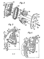
- FIG 2 is an exploded view of a feeding unit included in the feed mechanism of Figure 1.
- Figure 3 is a section along the line A-A in Figure 1 wherein certain parts have been excluded and wherein a tractor cover with idle rollers has been shown in two different positions corresponding to friction feeding of paper sheets and pin wheel feeding of continuous forms, respectively.
- Figure 4 is a section as in Figure 3, however showing the tractor cover with the idle rollers in a continuous-form loading position.
- a paper feed unit has been built up on a frame comprising an elongate frame portion 10 forming the bottom and back parts of the frame and two end walls 11, 12 secured to the frame portion 10 by means of screws 13, 14, 15.
- Two feed units 16, 17 for frictional feeding of paper sheets are journalled on shafts 18, 19 along which the units can be displaced to be set for different sheet widths.
- FIG 2 shows the structure of a friction feed unit.
- the unit comprises a casing 20 covered by a cover 21 which is secured to the casing by screws 22. Holes 23 in the cover co-operate in pairs with holes 24 in the casing to journal two gears 25, 26 which are supported on the shafts 18 and 19, respectively, in the frame.
- the gears have cogs 27 which mesh with a cog belt 28 interconnecting the two gears 25, 26 and transmitting movement from the gear 26 to the gear 25.
- the casing 20 has an opening 29 which exposes the smooth outer surface of the cog belt 28.
- the smooth surface is intended to be pressed against a sheet of paper, not shown, by idle rollers 30, see Figure 3.
- the idle rollers are arranged in tractor covers 31 of which one is provided for each feed unit.
- rollers 30 in pairs are journal- nailed on arms 32 which in turn are pivotally journalled on pins 33 in the cover.
- the two tractor covers 31 are swingably journalled on a shaft 34, the ends of which engage with grooves 35 in the two end walls 11, 12.
- the shaft 34 is supported by arms 36 which by pins 37 are swingably journalled in the respective end wall 11, 12.
- Springs 38 pull the shaft 34 in a direction towards the bottom of the grooves 35 and determine the force by which the idle rollers will press a sheet of paper against the cog belts 28.
- the cog belts 28 are driven via a shaft 19 which is connected to a driving wheel 39 driven by an electric motor, not shown.
- the shaft 19 has a square section as has also a corresponding hole 40 in the gear 26.
- Via the cog belt 28 motion is transmitted to the gear 25, which is journalled to rotate freely on the shaft 18.
- an extended driving surface will be provided which acts upon the paper sheet causing a very even feed of the said sheet to be achieved.
- pin wheels 41 are displaceably journalled on the shaft 19, one wheel to the left of the feed unit 16 and another to the right of the unit 17 in Figure 1.
- the wheels 41 are provided with feed pins 42 as well as with a flange 43, the function of which will appear more in detail below.
- the wheels 41 are connectible to the gears 26 in the respective feed unit 16, 17 and for this purpose each wheel has an axial hole 44 in which a coupling part 45 on the gear 26 can engage.
- a dog 46 on the coupling part 45 co-operates with the edge of the hole 44 to lock the two wheels 26, 41 in their position of interconnection.
- a guide plate 50 is provided having a shape conforming with the bending of the web as caused by the cog belt 28 and the idle rollers 30 in the respective feed unit.
- the guide plate 50 co-operates with a holder-on plate 51 secured to the shaft 34 and having rectangular wire loops 52 which are directed upwards and downwards and have a shape corresponding to the shape of the guide plate 50.
- the respective feed unit 16, 17 can be displaced to be set in the desired position. Locking of the respective feed unit in the set position is obtained by turning of a square shaft 53 which is journalled in the end walls 11, 12 and which extends through an oval hole 54 provided in the feed unit.
- Each feed unit 16, 17 can be set also in preprogrammed positions determined by grooves 59 in the shaft 53, compare Figure 1 a.
- a ball 61 can be caused to fall into the grooves under the biassing action of a spring 60, the ball being provided in a recess in the casing 20 of the feed unit.
- the tractor covers 31 are displaceable on the shaft 34 into positions connected with the positions of the feed units.
- these have been provided with a groove 62 intended to co-operate with the flange 43 on the pin wheel 49.
- the cover In positioning the right-hand cover 31 in Figure 1 over the feed unit 17 the cover is pivoted towards the wheel 49 and when the cover has taken the correct position the flange 43 falls into the groove 62.
- the flange 43 and the groove 62 co-operate only during the positioning of the tractor cover and, normally, they are positioned apart.
- the tractor cover can be designed such that during feeding by means of the pin wheels, the flange 43 rotates in the groove 62 preventing the tractor cover from being laterally displaced.
- Grooves 63 in the shaft 34 correspond to the preprogrammed positions determined by the grooves 59 in the shaft 53.
- a ball 65 biassed by a spring 64 and being provided in a recess in the cover 31 co-operates with the grooves 63. Accordingly, when any of the feed units 16, 17 has been set in a preprogrammed position determined by a groove 59 in the shaft 53 the corresponding tractor cover 31 can be set in the corresponding position on the shaft 34 by being displaced until the ball 65 falls into the groove 63 provided for this position.
- the sheet magazin comprises a shaft 66 which can be inserted into grooves 67 provided in the end walls 11, 12.
- the shaft 66 is locked in the groove 67 by a hook-shaped locking part 68 on an actuating lever 69 turnably journalled on the shaft 18.
- Such an actuating lever is provided close to the groove 67 in the respective end wall 11 12.
- the actuating lever 69 has a downward part 70, the free end of which is connected to the spring 38. As indicated above, at the respective end wall 11, 12 the opposite end of the spring 38 is secured to the arm 36 supporting the shaft 34. Hence, the position taken by the part 70 of the actuating lever determines the pressure exerted by the idle rollers 30 in the tractor covers 31. In the friction feed mode this pressure shall be of a predetermined magnitude which is achieved when the actuating lever 69 has taken the position shown in Figure 3.
- the friction feed mode is connected with the presence of a sheet magazin, and therefore the shaft 66 in the grooves 67 in the end walls determines the corresponding turning position of the actuating lever.
- the actuating lever In order to release the shaft 66 from the locking part 68 the actuating lever is provided with an operating arm 71, which when being pushed down turns the actuating lever anticlockwise and, accordingly, the locking part 68 away from the groove 67 in the respective end wall 11, 12. Then, the shaft 66 together with the sheet magazin can be removed.
- the shaft 34 with the tractor covers 31 can be moved into a loading position, shown in Figure 4 by dashed lines.
- the shaft can be locked in the loading position by a bent-over edge 72 on the arm 36 engaging an edge 73 on the actuating lever 69.
- By pushing-down of the operating arm 71 the shaft 34 can be released for return movement to the position shown in Figure 3.
- the paper feed mechanism according to the invention by the use of simple change-over measures can be used for either friction feed of sheets of paper from a sheet magazin or for pin- wheel feed of continuous forms at which the friction feed remains at a reduced pressure.
- This is of great importance in precise feed of continuous forms.
- Tolerances in the feed holes of the forms as well as of the feed pins of the pin wheels involve a small play between the holes and the pins, as seen in the direction of feed, and the influence of this play can be reduced if the friction feed remains in function.
- the pin wheel drive means In the friction feed mode the pin wheel drive means can be moved sideways into positions completely outside the paper sheet area.
Landscapes
- Handling Of Sheets (AREA)
- Advancing Webs (AREA)
Claims (12)
Applications Claiming Priority (2)
| Application Number | Priority Date | Filing Date | Title |
|---|---|---|---|
| SE8106001A SE440766B (sv) | 1981-10-09 | 1981-10-09 | Pappersmatningsanordning |
| SE8106001 | 1981-10-09 |
Publications (2)
| Publication Number | Publication Date |
|---|---|
| EP0089996A1 EP0089996A1 (fr) | 1983-10-05 |
| EP0089996B1 true EP0089996B1 (fr) | 1985-03-20 |
Family
ID=20344754
Family Applications (1)
| Application Number | Title | Priority Date | Filing Date |
|---|---|---|---|
| EP82902997A Expired EP0089996B1 (fr) | 1981-10-09 | 1982-09-27 | Mecanisme d'alimentation en papier |
Country Status (7)
| Country | Link |
|---|---|
| US (1) | US4501510A (fr) |
| EP (1) | EP0089996B1 (fr) |
| JP (1) | JPS58501668A (fr) |
| DE (1) | DE3262691D1 (fr) |
| IT (1) | IT1203643B (fr) |
| SE (1) | SE440766B (fr) |
| WO (1) | WO1983001227A1 (fr) |
Families Citing this family (4)
| Publication number | Priority date | Publication date | Assignee | Title |
|---|---|---|---|---|
| JPS60162U (ja) * | 1983-06-17 | 1985-01-05 | 蛇の目ミシン工業株式会社 | プリンタの印刷用紙装置 |
| JPS60191948A (ja) * | 1984-03-09 | 1985-09-30 | Tokyo Electric Co Ltd | 自動給紙装置 |
| US4815879A (en) * | 1984-11-20 | 1989-03-28 | Brother Kogyo Kabushiki Kaisha | Combined printer and sheet feeding apparatus |
| US4794429A (en) * | 1987-03-23 | 1988-12-27 | Xerox Corporation | Automatic dual mode sheet and web document transport for copiers |
Family Cites Families (12)
| Publication number | Priority date | Publication date | Assignee | Title |
|---|---|---|---|---|
| US830480A (en) * | 1905-06-07 | 1906-09-04 | Harvey A Moyer | Type-writing machine. |
| US2131152A (en) * | 1935-05-14 | 1938-09-27 | Underwood Elliott Fisher Co | Typewriting machine |
| US2280095A (en) * | 1940-08-08 | 1942-04-21 | Standard Register Co | Imprinting apparatus |
| US2426333A (en) * | 1941-04-24 | 1947-08-26 | Autographic Register Co | Paper feeding device for writing machines |
| US3421612A (en) * | 1965-08-30 | 1969-01-14 | Sperry Rand Corp | Lister attachment for high speed web printers |
| US3747820A (en) * | 1971-11-17 | 1973-07-24 | Ibm | Forms feeding device |
| US3838804A (en) * | 1973-05-10 | 1974-10-01 | Ibm | Non-shingling forms feed tractor |
| US3880016A (en) * | 1974-03-07 | 1975-04-29 | Qume Corp | Variable displacement apparatus for platen and tractor feed |
| CH591190A5 (fr) * | 1975-04-25 | 1977-09-15 | Hasler Ag | |
| US4368994A (en) * | 1976-07-14 | 1983-01-18 | The Singer Company | Single servo driven printer |
| US4307446A (en) * | 1979-05-02 | 1981-12-22 | Burroughs Corporation | Digital communication networks employing speed independent switches |
| IT1135127B (it) * | 1981-01-22 | 1986-08-20 | Honeywell Inf Systems | Meccanismo di trasporto carta per stampante |
-
1981
- 1981-10-09 SE SE8106001A patent/SE440766B/sv unknown
-
1982
- 1982-09-27 EP EP82902997A patent/EP0089996B1/fr not_active Expired
- 1982-09-27 JP JP57503039A patent/JPS58501668A/ja active Pending
- 1982-09-27 US US06/503,368 patent/US4501510A/en not_active Expired - Fee Related
- 1982-09-27 DE DE8282902997T patent/DE3262691D1/de not_active Expired
- 1982-09-27 WO PCT/SE1982/000298 patent/WO1983001227A1/fr not_active Ceased
- 1982-10-07 IT IT49224/82A patent/IT1203643B/it active
Also Published As
| Publication number | Publication date |
|---|---|
| IT1203643B (it) | 1989-02-15 |
| SE8106001L (sv) | 1983-04-10 |
| EP0089996A1 (fr) | 1983-10-05 |
| IT8249224A0 (it) | 1982-10-07 |
| DE3262691D1 (en) | 1985-04-25 |
| JPS58501668A (ja) | 1983-10-06 |
| US4501510A (en) | 1985-02-26 |
| WO1983001227A1 (fr) | 1983-04-14 |
| SE440766B (sv) | 1985-08-19 |
Similar Documents
| Publication | Publication Date | Title |
|---|---|---|
| JPH03244569A (ja) | プリンタ | |
| US4269522A (en) | Bi-directional record material feed apparatus | |
| EP0295172B1 (fr) | Dispositif d'alimentation en papier pour imprimante | |
| GB2073154A (en) | Detachable web feeder for printer | |
| US4501510A (en) | Apparatus for feeding sheets of material and continuous webs in printers and typewriters | |
| CA1324027C (fr) | Dispositif d'impression thermique | |
| EP0368685A2 (fr) | Dispositif d'avance et de réception de feuilles utilisé avec une imprimante | |
| EP0443444B1 (fr) | Imprimante avec plusieurs configurations pour le montage de tracteur | |
| GB2034673A (en) | Record webs pin feed devices with threading means | |
| US5123583A (en) | Paper feeder for printers | |
| US4235360A (en) | Bi-directional pin feed apparatus | |
| JPS6110996Y2 (fr) | ||
| JP2576471B2 (ja) | プリンタの紙押さえ装置 | |
| US4859098A (en) | Paper feeder for a printer | |
| JPH028781Y2 (fr) | ||
| JPH062986Y2 (ja) | プリンタの用紙供給装置 | |
| US5181641A (en) | Tractor feed for perforated webs | |
| KR960001970B1 (ko) | 프린터의 용지 자동 이송장치 | |
| JPS5931404Y2 (ja) | 輪転式印刷機の切断制御装置 | |
| JPS6299171A (ja) | フオ−ムトラクタ内蔵型プリンタ | |
| JPH0145433B2 (fr) | ||
| JPH0577992A (ja) | プリンタの紙送り装置 | |
| JPH0320124Y2 (fr) | ||
| JPS63282040A (ja) | プリンタの紙送り装置 | |
| JPS61283579A (ja) | 単票ガイド付トラクタ装置 |
Legal Events
| Date | Code | Title | Description |
|---|---|---|---|
| PUAI | Public reference made under article 153(3) epc to a published international application that has entered the european phase |
Free format text: ORIGINAL CODE: 0009012 |
|
| 17P | Request for examination filed |
Effective date: 19830426 |
|
| AK | Designated contracting states |
Designated state(s): DE FR GB NL |
|
| GRAA | (expected) grant |
Free format text: ORIGINAL CODE: 0009210 |
|
| AK | Designated contracting states |
Designated state(s): DE FR GB NL |
|
| REF | Corresponds to: |
Ref document number: 3262691 Country of ref document: DE Date of ref document: 19850425 |
|
| ET | Fr: translation filed | ||
| PLBE | No opposition filed within time limit |
Free format text: ORIGINAL CODE: 0009261 |
|
| STAA | Information on the status of an ep patent application or granted ep patent |
Free format text: STATUS: NO OPPOSITION FILED WITHIN TIME LIMIT |
|
| PG25 | Lapsed in a contracting state [announced via postgrant information from national office to epo] |
Ref country code: NL Effective date: 19860401 |
|
| 26N | No opposition filed | ||
| NLV4 | Nl: lapsed or anulled due to non-payment of the annual fee | ||
| PG25 | Lapsed in a contracting state [announced via postgrant information from national office to epo] |
Ref country code: FR Free format text: LAPSE BECAUSE OF NON-PAYMENT OF DUE FEES Effective date: 19860530 |
|
| PG25 | Lapsed in a contracting state [announced via postgrant information from national office to epo] |
Ref country code: DE Effective date: 19860603 |
|
| REG | Reference to a national code |
Ref country code: FR Ref legal event code: ST |
|
| GBPC | Gb: european patent ceased through non-payment of renewal fee | ||
| PG25 | Lapsed in a contracting state [announced via postgrant information from national office to epo] |
Ref country code: GB Effective date: 19881122 |
|
| REG | Reference to a national code |
Ref country code: FR Ref legal event code: ST |