EP0090252A1 - Verfahren und Öfen zur Herstellung von Siliziumcarbid - Google Patents
Verfahren und Öfen zur Herstellung von Siliziumcarbid Download PDFInfo
- Publication number
- EP0090252A1 EP0090252A1 EP83102511A EP83102511A EP0090252A1 EP 0090252 A1 EP0090252 A1 EP 0090252A1 EP 83102511 A EP83102511 A EP 83102511A EP 83102511 A EP83102511 A EP 83102511A EP 0090252 A1 EP0090252 A1 EP 0090252A1
- Authority
- EP
- European Patent Office
- Prior art keywords
- silicon carbide
- slabs
- gates
- temperature
- mix
- Prior art date
- Legal status (The legal status is an assumption and is not a legal conclusion. Google has not performed a legal analysis and makes no representation as to the accuracy of the status listed.)
- Granted
Links
- HBMJWWWQQXIZIP-UHFFFAOYSA-N silicon carbide Chemical compound [Si+]#[C-] HBMJWWWQQXIZIP-UHFFFAOYSA-N 0.000 title claims abstract description 46
- 229910010271 silicon carbide Inorganic materials 0.000 title claims abstract description 31
- 238000000034 method Methods 0.000 title claims description 7
- VYPSYNLAJGMNEJ-UHFFFAOYSA-N Silicium dioxide Chemical compound O=[Si]=O VYPSYNLAJGMNEJ-UHFFFAOYSA-N 0.000 claims abstract description 33
- 239000000203 mixture Substances 0.000 claims abstract description 30
- 239000000571 coke Substances 0.000 claims abstract description 17
- 229910021419 crystalline silicon Inorganic materials 0.000 claims abstract description 15
- 238000004519 manufacturing process Methods 0.000 claims abstract description 13
- 239000013078 crystal Substances 0.000 claims abstract description 11
- 239000004615 ingredient Substances 0.000 claims abstract description 6
- 239000011541 reaction mixture Substances 0.000 claims abstract description 5
- 239000000377 silicon dioxide Substances 0.000 claims abstract description 5
- 238000012856 packing Methods 0.000 claims abstract 2
- 238000006243 chemical reaction Methods 0.000 claims description 37
- OKTJSMMVPCPJKN-UHFFFAOYSA-N Carbon Chemical compound [C] OKTJSMMVPCPJKN-UHFFFAOYSA-N 0.000 claims description 23
- 239000004576 sand Substances 0.000 claims description 22
- 229910002804 graphite Inorganic materials 0.000 claims description 18
- 239000010439 graphite Substances 0.000 claims description 18
- 239000011449 brick Substances 0.000 claims description 7
- 239000006229 carbon black Substances 0.000 claims description 7
- 238000009413 insulation Methods 0.000 claims description 5
- 229910052799 carbon Inorganic materials 0.000 claims description 4
- 239000010425 asbestos Substances 0.000 claims description 2
- 238000002844 melting Methods 0.000 claims description 2
- 230000008018 melting Effects 0.000 claims description 2
- 229910052895 riebeckite Inorganic materials 0.000 claims description 2
- 239000000463 material Substances 0.000 description 5
- 239000000047 product Substances 0.000 description 4
- 239000012535 impurity Substances 0.000 description 3
- 238000001953 recrystallisation Methods 0.000 description 3
- PNEYBMLMFCGWSK-UHFFFAOYSA-N aluminium oxide Inorganic materials [O-2].[O-2].[O-2].[Al+3].[Al+3] PNEYBMLMFCGWSK-UHFFFAOYSA-N 0.000 description 2
- 239000007795 chemical reaction product Substances 0.000 description 2
- 239000002131 composite material Substances 0.000 description 2
- 238000010438 heat treatment Methods 0.000 description 2
- 238000010521 absorption reaction Methods 0.000 description 1
- 230000015572 biosynthetic process Effects 0.000 description 1
- 238000009529 body temperature measurement Methods 0.000 description 1
- 238000010276 construction Methods 0.000 description 1
- 239000002178 crystalline material Substances 0.000 description 1
- 230000006698 induction Effects 0.000 description 1
- 238000012544 monitoring process Methods 0.000 description 1
- 230000003287 optical effect Effects 0.000 description 1
- 230000003647 oxidation Effects 0.000 description 1
- 238000007254 oxidation reaction Methods 0.000 description 1
- 239000000843 powder Substances 0.000 description 1
- 238000004064 recycling Methods 0.000 description 1
- 238000012958 reprocessing Methods 0.000 description 1
- 238000003786 synthesis reaction Methods 0.000 description 1
- 239000002699 waste material Substances 0.000 description 1
Images
Classifications
-
- H—ELECTRICITY
- H05—ELECTRIC TECHNIQUES NOT OTHERWISE PROVIDED FOR
- H05B—ELECTRIC HEATING; ELECTRIC LIGHT SOURCES NOT OTHERWISE PROVIDED FOR; CIRCUIT ARRANGEMENTS FOR ELECTRIC LIGHT SOURCES, IN GENERAL
- H05B3/00—Ohmic-resistance heating
- H05B3/60—Heating arrangements wherein the heating current flows through granular powdered or fluid material, e.g. for salt-bath furnace, electrolytic heating
-
- C—CHEMISTRY; METALLURGY
- C01—INORGANIC CHEMISTRY
- C01B—NON-METALLIC ELEMENTS; COMPOUNDS THEREOF; METALLOIDS OR COMPOUNDS THEREOF NOT COVERED BY SUBCLASS C01C
- C01B32/00—Carbon; Compounds thereof
- C01B32/90—Carbides
- C01B32/914—Carbides of single elements
- C01B32/956—Silicon carbide
- C01B32/963—Preparation from compounds containing silicon
- C01B32/97—Preparation from SiO or SiO2
-
- C—CHEMISTRY; METALLURGY
- C01—INORGANIC CHEMISTRY
- C01P—INDEXING SCHEME RELATING TO STRUCTURAL AND PHYSICAL ASPECTS OF SOLID INORGANIC COMPOUNDS
- C01P2006/00—Physical properties of inorganic compounds
- C01P2006/80—Compositional purity
Definitions
- This invention relates to an Acheson type silicon carbide production furnace.
- a description of an Acheson type silicon carbide furnace is included in U.S. Reissue Patent 11,473 to Acheson re-issued February 26, 1895.
- a carbon core resistor element is used and when the reaction has been completed, silicon carbide crystals surround the carbon rod in a zone that remains embedded in a more or less unreacted mix.
- the Acheson furnace may be operated on a "green run” basis with a charge composed of fresh sand and coke that is heated to reaction temperatures to produce silicon carbide. During a green run about 50% of the mass is reacted to form silicon carbide crystals with impurities migrating from the reaction zone into a surrounding partially reacted mix that also contains some silicon carbide crystals, the partially reacted mix being called fire sand.
- the fire sand is mixed with additional sand and coke for making a "black run" in which the reacting mixture includes the small proportion of silicon carbide formed in the fire sand of the previous run, the impurities from that run, and the newly added sand and coke.
- this increase in production efficiency is accomplished with a new gate or wall structure for containing the mass of ingredients to be reacted which permits the performance of a method of reacting the mass under more controlled temperature conditions to increase the proportionate yield of the desired coarsely grained silicon carbide product.
- the wall for the Acheson furnace made in accordance with this invention includes a basic wall slab made of a material having a melting point above 2400°C., which has a low vapor-pressure at such an elevated temperature and is also inert to silicon carbide at this temperature.
- the preferred wall is basically a composite structure making use of a plurality of graphite slabs with a layer of carbon black heat insulation between the graphite elements and a support backing. The graphite is exposed directly to the reaction mix during performance of the process without detriment to the composite wall structure so that it is possible to construct the body of the furnace in a size adapted to contain a reacting mass that may be more completely converted to silicon carbide at temperatures within the range that are known to produce the desired more coarsely crystalline silicon carbide product.
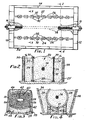
- the furnace shown in Fi g . 1 includes end walls 10 and 12 following the pattern of the known Acheson type furnace shown in the patented prior art references cited above.
- the furnace is provided with the usual carbon or graphite resistor 14 made up of coke and/or graphite from previous runs disposed centrally through the reaction chamber in a trough formed in the mixture of sand and coke.
- the resistor is connected to electrodes 16 and 18 for passing the required current through the resistor to drive the reaction for producing silicon carbide.
- a suitable stoichiometric mix of silica and coke together with fire sand, if there is such material available, is positioned within the reaction chamber 20, to the level of the electrodes 16 and 18.
- the furnace is completely filled with the mixture of coke and sand, as known in the art.
- the furnace chamber is defined by the end walls 10 and 12, side walls 22 and 24 and the floor 25 shown in Figs. 2 and 3.
- the walls 22 and 24 are each formed of a series of substantially identical graphite blocks 26 standing in spaced apart vertical positions, the inner faces of which blocks define the sides of the reaction chamber 20.
- the graphite blocks or slabs which in this example of a small furnace are in the range of about 2.5 cm or 1" thick, 30 cm or about one foot wide and about 1 meter or approximately 3 1 high, may be held positioned at the floor level in grooved alumina bricks 28 to have their inner faces disposed generally parallel to the center-line of resistor 14.
- the upper ends of slabs 26 may be fixed with similarly grooved alumina bricks 30 that bridge the spaces left between the individual slabs.
- the spaces are in the order of about 2.5 cm or 1" to avoid making a good electrical contact between the plates which might otherwise provide a path for a short circuit between the resistor bar and the ground.
- the spaces between the adjacent edges of the slabs are each filled with a graphite felt strip 32,
- a space is provided behind the back sides of the slabs that face away from chamber 20 and the fire brick support walls 34 on the opposite sides of the furnace which spaces are about 15 to 30 cms or 6" to 12" wide, that are each adapted to be filled with carbon black powder 36.
- the graphite felt strips prevent the carbon black from flowing through the space provided between the slabs 26 and the wide masses of carbon black behind the graphite slabs 26 provide heat insulation to protect the refractory brick walls 34 from the reaction temperatures generated within the reacting mass held in the reaction chamber 20.
- the inside surfaces of walls 34 may be lined with a layer of asbestos paper.
- the reaction chamber 20 that is defined by the end walls 10 and 12, inner faces of the vertically disposed graphite slabs 26 and the floor 25 is designed to be loaded and unloaded either from above or from the ends of the furnace by removal of the portions of end walls 10 and 12, without removal of or disturbing the position of the respective insulated graphite slabs 26 forming walls 22 and 24.
- the reaction chamber is loaded with a stoichiometric mixture of fresh sand and coke together with reclaimed fire sand from an earlier run as in a normal Acheson furnacing operation.
- the reaction mix is packed around the resistor 14 and then electrical power is fed to the resistor at the required voltages to generate the temperatures within the reacting mass needed to produce silicon carbide.
- Temperature measurements are made throughout the mass being reacted during the run and by means of an optical pyrometer means within graphite tubes disposed at several points along the walls, the temperatures developed within the reacting mass and next to the inner faces of the graphite slabs 26 are monitored.
- the run is continued until the temperature at the inner faces of slabs 26 reaches a range of at least 2000°C. to 2500°C. and preferably between 2000° C . to 2240°C. for at least one hour.
- the reaction to produce silicon carbide requires sufficient temperature for the volatilization of the Si0 2 and requires about 2.6 KWH of energy per pound of fine crystalline silicon carbide initially converted from the reaction of sand and coke in the mix, at about 1800°C. Further energy is required to heat this finely crystalline silicon carbide to a temperature within a range up to no higher than about 2500°C. to promote crystal growth to the coarse crystalline form desired for certain commercial uses, but only 0.3 KWH per pound of silicon carbide is required for growing the coarse crystals once the fine crystalline reaction product has been made.
- the insulated wall structure disclosed herein confines the reacting mass so that substantially all of the sand and coke between the resistor element and the walls 22 and 24 of the reaction zone in the furnace is reacted to form silicon carbide and then the mass within chamber 20 can thereafter be progressively heated up from about 1800°C. to a temperature within a range where crystal growth or recrystallization takes place.
- the reaction can best be controlled to assure the most efficient production of the coarse grained recrystallized silicon carbide as desired.
- a zone 40 of coarsely crystalline silicon carbide is produced that extends from one wall 22 to the opposite wall 24. This zone is surrounded top and bottom with fire sand zone 42 and beyond the zones 42 and 44 there is the zones 46 high in impurities and unreacted mix.
- the electrical supply can be discontinued and the furnace allowed to cool for a period of 2 to 3 days.
- the coarse crystals have grown outwardly to the insulated side walls 22 and 24 but the top and bottom zones of the reacting mass which were not insulated are covered with a small volume of fire sand and partly reacted and unreacted mix as compared with the end product found in a conventional Acheson furnace where the fire sand surrounds the entire zone of reacted material.
- the walls 22 and 24 may be shaped to generally concentrically match the contour of the growing silicon carbide pig. This will maximize the advantages of using the insulated gate structure for increased coarsely crystalline silicon carbide.
- the walls may extend partially or totally around the bottom of the mix to meet at 51. Supporting piers of refractory fire brick 50 are positioned as needed.
- the gate thickness should be held to a minimum in order to minimize the loss of heat due to absorption of energy from the reaction mass. It is desireable to cool the electrode end for protection against oxidation and to the extent possible, to insulate the ends of the furnace. Shorting of the current to ground must be avoided.
Landscapes
- Chemical & Material Sciences (AREA)
- Organic Chemistry (AREA)
- Inorganic Chemistry (AREA)
- Carbon And Carbon Compounds (AREA)
- Silicon Compounds (AREA)
- Ceramic Products (AREA)
- Vertical, Hearth, Or Arc Furnaces (AREA)
Priority Applications (1)
| Application Number | Priority Date | Filing Date | Title |
|---|---|---|---|
| AT83102511T ATE16473T1 (de) | 1982-03-29 | 1983-03-14 | Verfahren und oefen zur herstellung von siliziumcarbid. |
Applications Claiming Priority (2)
| Application Number | Priority Date | Filing Date | Title |
|---|---|---|---|
| US06/362,701 US4419336A (en) | 1982-03-29 | 1982-03-29 | Silicon carbide production and furnace |
| US362701 | 1989-06-07 |
Publications (2)
| Publication Number | Publication Date |
|---|---|
| EP0090252A1 true EP0090252A1 (de) | 1983-10-05 |
| EP0090252B1 EP0090252B1 (de) | 1985-11-13 |
Family
ID=23427177
Family Applications (1)
| Application Number | Title | Priority Date | Filing Date |
|---|---|---|---|
| EP83102511A Expired EP0090252B1 (de) | 1982-03-29 | 1983-03-14 | Verfahren und Öfen zur Herstellung von Siliziumcarbid |
Country Status (11)
| Country | Link |
|---|---|
| US (1) | US4419336A (de) |
| EP (1) | EP0090252B1 (de) |
| JP (1) | JPS58217415A (de) |
| AT (1) | ATE16473T1 (de) |
| AU (1) | AU559627B2 (de) |
| BR (1) | BR8301537A (de) |
| CA (1) | CA1178022A (de) |
| DE (1) | DE3361199D1 (de) |
| IN (1) | IN158213B (de) |
| NO (1) | NO160843C (de) |
| ZA (1) | ZA831649B (de) |
Cited By (2)
| Publication number | Priority date | Publication date | Assignee | Title |
|---|---|---|---|---|
| WO1995033683A1 (en) * | 1994-06-06 | 1995-12-14 | Norton As | Process for producing silicon carbide |
| KR100834195B1 (ko) * | 2000-11-21 | 2008-05-30 | 모사이드 테크놀로지스, 인코포레이티드 | 전하펌프 전원 공급장치 |
Families Citing this family (16)
| Publication number | Priority date | Publication date | Assignee | Title |
|---|---|---|---|---|
| US4756895A (en) * | 1986-08-22 | 1988-07-12 | Stemcor Corporation | Hexagonal silicon carbide platelets and preforms and methods for making and using same |
| US5176893A (en) * | 1989-10-02 | 1993-01-05 | Phillips Petroleum Company | Silicon nitride products and method for their production |
| US5108729A (en) * | 1989-10-02 | 1992-04-28 | Phillips Petroleum Company | Production of carbide products |
| US5165916A (en) * | 1989-10-02 | 1992-11-24 | Phillips Petroleum Company | Method for producing carbide products |
| JP2579561B2 (ja) * | 1991-03-22 | 1997-02-05 | 東海カーボン株式会社 | SiCウイスカーの製造装置 |
| US5128115A (en) * | 1991-04-08 | 1992-07-07 | The United States Of America As Represented By The United States Department Of Energy | Manufacture of silicon carbide using solar energy |
| US5324494A (en) * | 1993-01-21 | 1994-06-28 | Midwest Research Institute | Method for silicon carbide production by reacting silica with hydrocarbon gas |
| US5679153A (en) * | 1994-11-30 | 1997-10-21 | Cree Research, Inc. | Method for reducing micropipe formation in the epitaxial growth of silicon carbide and resulting silicon carbide structures |
| JP2884085B1 (ja) * | 1998-04-13 | 1999-04-19 | 日本ピラー工業株式会社 | 単結晶SiCおよびその製造方法 |
| JP4734711B2 (ja) * | 2000-12-04 | 2011-07-27 | 株式会社Ihi | 黒鉛化電気炉の温度制御方法および温度制御装置 |
| CN102278885B (zh) * | 2011-07-01 | 2013-05-01 | 段晓燕 | 一种收集碳化硅冶炼炉气体的炉侧墙 |
| FR2977578B1 (fr) * | 2011-07-06 | 2013-07-05 | Produits Refractaires | Procede de fabrication de carbure de silicium |
| TWI542542B (zh) * | 2011-08-24 | 2016-07-21 | 太平洋水泥股份有限公司 | 碳化矽粉末及其製造方法 |
| CN103964441B (zh) * | 2014-05-13 | 2015-12-09 | 神华集团有限责任公司 | 利用除尘粉冶炼碳化硅的方法 |
| JP6489807B2 (ja) * | 2014-11-26 | 2019-03-27 | 太平洋セメント株式会社 | 電気抵抗炉及びこれを用いた炭化珪素の製造方法 |
| CN105060296B (zh) * | 2015-07-23 | 2017-03-15 | 西安科技大学 | 一种热源并联式碳化硅合成炉 |
Citations (5)
| Publication number | Priority date | Publication date | Assignee | Title |
|---|---|---|---|---|
| US1044295A (en) * | 1907-06-14 | 1912-11-12 | Frank J Tone | Process of producing silicon carbid. |
| US2005956A (en) * | 1931-12-02 | 1935-06-25 | Norton Co | Method of making abrasive metal carbides and an apparatus therefor |
| SU121119A1 (ru) * | 1958-12-17 | 1959-11-30 | В.Л. Алферов | Способ получени карбида кремни в электропечах |
| DE2364108B2 (de) * | 1973-12-21 | 1975-11-27 | Elektroschmelzwerk Kempten Gmbh, 8000 Muenchen | Durch direkte elektrische Heizung nach dem Widerstandprinzip betriebene Ofenanlage, insbesondere zur Herstellung von Siliciumcarbid |
| US3962406A (en) * | 1967-11-25 | 1976-06-08 | U.S. Philips Corporation | Method of manufacturing silicon carbide crystals |
Family Cites Families (5)
| Publication number | Priority date | Publication date | Assignee | Title |
|---|---|---|---|---|
| US11473A (en) * | 1854-08-08 | Sawing and iplaning machine | ||
| US2178773A (en) * | 1935-11-13 | 1939-11-07 | Carborundum Co | Silicon carbide and manufacture thereof |
| US3375073A (en) * | 1960-11-14 | 1968-03-26 | Carborundum Co | Process and apparatus for effecting solid-state reactions |
| US3773553A (en) * | 1969-03-27 | 1973-11-20 | Norton Co | Silicon carbide junction diode |
| DD114673A5 (de) * | 1973-12-21 | 1975-08-12 |
-
1982
- 1982-03-29 US US06/362,701 patent/US4419336A/en not_active Expired - Lifetime
-
1983
- 1983-01-26 CA CA000420276A patent/CA1178022A/en not_active Expired
- 1983-03-09 AU AU12172/83A patent/AU559627B2/en not_active Ceased
- 1983-03-10 ZA ZA831649A patent/ZA831649B/xx unknown
- 1983-03-14 AT AT83102511T patent/ATE16473T1/de not_active IP Right Cessation
- 1983-03-14 DE DE8383102511T patent/DE3361199D1/de not_active Expired
- 1983-03-14 EP EP83102511A patent/EP0090252B1/de not_active Expired
- 1983-03-18 IN IN331/CAL/83A patent/IN158213B/en unknown
- 1983-03-23 NO NO831036A patent/NO160843C/no unknown
- 1983-03-24 JP JP58049661A patent/JPS58217415A/ja active Pending
- 1983-03-24 BR BR8301537A patent/BR8301537A/pt unknown
Patent Citations (5)
| Publication number | Priority date | Publication date | Assignee | Title |
|---|---|---|---|---|
| US1044295A (en) * | 1907-06-14 | 1912-11-12 | Frank J Tone | Process of producing silicon carbid. |
| US2005956A (en) * | 1931-12-02 | 1935-06-25 | Norton Co | Method of making abrasive metal carbides and an apparatus therefor |
| SU121119A1 (ru) * | 1958-12-17 | 1959-11-30 | В.Л. Алферов | Способ получени карбида кремни в электропечах |
| US3962406A (en) * | 1967-11-25 | 1976-06-08 | U.S. Philips Corporation | Method of manufacturing silicon carbide crystals |
| DE2364108B2 (de) * | 1973-12-21 | 1975-11-27 | Elektroschmelzwerk Kempten Gmbh, 8000 Muenchen | Durch direkte elektrische Heizung nach dem Widerstandprinzip betriebene Ofenanlage, insbesondere zur Herstellung von Siliciumcarbid |
Cited By (3)
| Publication number | Priority date | Publication date | Assignee | Title |
|---|---|---|---|---|
| WO1995033683A1 (en) * | 1994-06-06 | 1995-12-14 | Norton As | Process for producing silicon carbide |
| US6022515A (en) * | 1994-06-06 | 2000-02-08 | Norton As | Process for producing silicon carbide |
| KR100834195B1 (ko) * | 2000-11-21 | 2008-05-30 | 모사이드 테크놀로지스, 인코포레이티드 | 전하펌프 전원 공급장치 |
Also Published As
| Publication number | Publication date |
|---|---|
| NO160843C (no) | 1989-06-07 |
| AU559627B2 (en) | 1987-03-19 |
| AU1217283A (en) | 1984-07-05 |
| BR8301537A (pt) | 1983-12-06 |
| IN158213B (de) | 1986-09-27 |
| ATE16473T1 (de) | 1985-11-15 |
| EP0090252B1 (de) | 1985-11-13 |
| DE3361199D1 (en) | 1985-12-19 |
| NO831036L (no) | 1983-09-30 |
| ZA831649B (en) | 1983-11-30 |
| CA1178022A (en) | 1984-11-20 |
| US4419336A (en) | 1983-12-06 |
| JPS58217415A (ja) | 1983-12-17 |
| NO160843B (no) | 1989-02-27 |
Similar Documents
| Publication | Publication Date | Title |
|---|---|---|
| EP0090252B1 (de) | Verfahren und Öfen zur Herstellung von Siliziumcarbid | |
| US2178773A (en) | Silicon carbide and manufacture thereof | |
| EP0766645B1 (de) | Verfahren zur herstellung von siliciumcarbid | |
| US4430187A (en) | Reduction cell pot | |
| US2005956A (en) | Method of making abrasive metal carbides and an apparatus therefor | |
| CA1070477A (en) | Electrical resistance furnace for the production of silicon carbide | |
| US4673481A (en) | Reduction pot | |
| JPH0137458B2 (de) | ||
| EP0062356B1 (de) | Vorrichtung zum induktiven Erwärmen, Verfahren zum Erwärmen unter Verwendung eines Wärmeisolators und so erwärmte Werkstücke | |
| US3348915A (en) | Method for producing a crystalline carbide, boride or silicide | |
| EP0142459B1 (de) | Elektrolysewanne | |
| CN108658078A (zh) | 一种碳化硅冶炼工艺 | |
| US5058126A (en) | Silicon carbide beam as refractory in an open-arc furnace | |
| US3142717A (en) | Apparatus for producing quartz | |
| US4289537A (en) | Method of producing cement | |
| CA1139530A (en) | Method of producing tricalcium silicate | |
| SU740866A1 (ru) | Способ обжига и пуска электролизера дл получени алюмини | |
| JPH0238548B2 (de) | ||
| SU1092348A1 (ru) | Способ монтажа хлоратора | |
| CA1167499A (en) | Arcuate silicon carbide manufacturing plant | |
| CA1160647A (en) | Method for producing cement | |
| JPS57191217A (en) | Improving method for quality of silicon carbide | |
| SU737363A1 (ru) | Трехфазна электрическа стекловаренна печь | |
| SU1186914A1 (ru) | Ретортна печь дл прокалки кускового материала | |
| US1306289A (en) | Vanxa |
Legal Events
| Date | Code | Title | Description |
|---|---|---|---|
| PUAI | Public reference made under article 153(3) epc to a published international application that has entered the european phase |
Free format text: ORIGINAL CODE: 0009012 |
|
| AK | Designated contracting states |
Designated state(s): AT CH DE FR IT LI |
|
| RBV | Designated contracting states (corrected) |
Designated state(s): AT CH DE FR IT LI |
|
| 17P | Request for examination filed |
Effective date: 19831107 |
|
| GRAA | (expected) grant |
Free format text: ORIGINAL CODE: 0009210 |
|
| AK | Designated contracting states |
Designated state(s): AT CH DE FR IT LI |
|
| REF | Corresponds to: |
Ref document number: 16473 Country of ref document: AT Date of ref document: 19851115 Kind code of ref document: T |
|
| ITF | It: translation for a ep patent filed | ||
| REF | Corresponds to: |
Ref document number: 3361199 Country of ref document: DE Date of ref document: 19851219 |
|
| ET | Fr: translation filed | ||
| PLBE | No opposition filed within time limit |
Free format text: ORIGINAL CODE: 0009261 |
|
| STAA | Information on the status of an ep patent application or granted ep patent |
Free format text: STATUS: NO OPPOSITION FILED WITHIN TIME LIMIT |
|
| 26N | No opposition filed | ||
| PGFP | Annual fee paid to national office [announced via postgrant information from national office to epo] |
Ref country code: FR Payment date: 19890124 Year of fee payment: 7 |
|
| PGFP | Annual fee paid to national office [announced via postgrant information from national office to epo] |
Ref country code: CH Payment date: 19890127 Year of fee payment: 7 |
|
| PGFP | Annual fee paid to national office [announced via postgrant information from national office to epo] |
Ref country code: AT Payment date: 19890209 Year of fee payment: 7 |
|
| PGFP | Annual fee paid to national office [announced via postgrant information from national office to epo] |
Ref country code: DE Payment date: 19890214 Year of fee payment: 7 |
|
| ITTA | It: last paid annual fee | ||
| PG25 | Lapsed in a contracting state [announced via postgrant information from national office to epo] |
Ref country code: AT Effective date: 19900314 |
|
| PG25 | Lapsed in a contracting state [announced via postgrant information from national office to epo] |
Ref country code: LI Effective date: 19900331 Ref country code: CH Effective date: 19900331 |
|
| PG25 | Lapsed in a contracting state [announced via postgrant information from national office to epo] |
Ref country code: FR Effective date: 19901130 |
|
| REG | Reference to a national code |
Ref country code: CH Ref legal event code: PL |
|
| PG25 | Lapsed in a contracting state [announced via postgrant information from national office to epo] |
Ref country code: DE Effective date: 19901201 |
|
| REG | Reference to a national code |
Ref country code: FR Ref legal event code: ST |