EP0090345B1 - Système de suppression des vibrations pour moteur diesel - Google Patents
Système de suppression des vibrations pour moteur diesel Download PDFInfo
- Publication number
- EP0090345B1 EP0090345B1 EP83102899A EP83102899A EP0090345B1 EP 0090345 B1 EP0090345 B1 EP 0090345B1 EP 83102899 A EP83102899 A EP 83102899A EP 83102899 A EP83102899 A EP 83102899A EP 0090345 B1 EP0090345 B1 EP 0090345B1
- Authority
- EP
- European Patent Office
- Prior art keywords
- engine
- intake air
- throttle valve
- oil pressure
- switch
- Prior art date
- Legal status (The legal status is an assumption and is not a legal conclusion. Google has not performed a legal analysis and makes no representation as to the accuracy of the status listed.)
- Expired
Links
- 230000001629 suppression Effects 0.000 title description 7
- 239000000446 fuel Substances 0.000 claims description 26
- 238000002485 combustion reaction Methods 0.000 claims description 21
- 239000003921 oil Substances 0.000 claims description 19
- 238000010438 heat treatment Methods 0.000 claims description 14
- 239000010687 lubricating oil Substances 0.000 claims description 10
- 239000000919 ceramic Substances 0.000 claims description 9
- 230000003247 decreasing effect Effects 0.000 claims description 6
- 238000011144 upstream manufacturing Methods 0.000 claims description 2
- 230000006835 compression Effects 0.000 description 15
- 238000007906 compression Methods 0.000 description 15
- 238000002347 injection Methods 0.000 description 10
- 239000007924 injection Substances 0.000 description 10
- 230000001133 acceleration Effects 0.000 description 5
- 230000001788 irregular Effects 0.000 description 3
- 230000001419 dependent effect Effects 0.000 description 2
- 230000000694 effects Effects 0.000 description 2
- 238000004880 explosion Methods 0.000 description 2
- 238000005461 lubrication Methods 0.000 description 2
- 239000000203 mixture Substances 0.000 description 2
- 238000010586 diagram Methods 0.000 description 1
- 229920001971 elastomer Polymers 0.000 description 1
- 230000005611 electricity Effects 0.000 description 1
- 230000020169 heat generation Effects 0.000 description 1
- 238000009434 installation Methods 0.000 description 1
- 239000012212 insulator Substances 0.000 description 1
- 238000004519 manufacturing process Methods 0.000 description 1
- 239000005060 rubber Substances 0.000 description 1
Images




Classifications
-
- F—MECHANICAL ENGINEERING; LIGHTING; HEATING; WEAPONS; BLASTING
- F02—COMBUSTION ENGINES; HOT-GAS OR COMBUSTION-PRODUCT ENGINE PLANTS
- F02D—CONTROLLING COMBUSTION ENGINES
- F02D9/00—Controlling engines by throttling air or fuel-and-air induction conduits or exhaust conduits
- F02D9/02—Controlling engines by throttling air or fuel-and-air induction conduits or exhaust conduits concerning induction conduits
-
- F—MECHANICAL ENGINEERING; LIGHTING; HEATING; WEAPONS; BLASTING
- F02—COMBUSTION ENGINES; HOT-GAS OR COMBUSTION-PRODUCT ENGINE PLANTS
- F02M—SUPPLYING COMBUSTION ENGINES IN GENERAL WITH COMBUSTIBLE MIXTURES OR CONSTITUENTS THEREOF
- F02M31/00—Apparatus for thermally treating combustion-air, fuel, or fuel-air mixture
- F02M31/02—Apparatus for thermally treating combustion-air, fuel, or fuel-air mixture for heating
- F02M31/12—Apparatus for thermally treating combustion-air, fuel, or fuel-air mixture for heating electrically
- F02M31/13—Combustion air
-
- F—MECHANICAL ENGINEERING; LIGHTING; HEATING; WEAPONS; BLASTING
- F02—COMBUSTION ENGINES; HOT-GAS OR COMBUSTION-PRODUCT ENGINE PLANTS
- F02B—INTERNAL-COMBUSTION PISTON ENGINES; COMBUSTION ENGINES IN GENERAL
- F02B3/00—Engines characterised by air compression and subsequent fuel addition
- F02B3/06—Engines characterised by air compression and subsequent fuel addition with compression ignition
-
- F—MECHANICAL ENGINEERING; LIGHTING; HEATING; WEAPONS; BLASTING
- F02—COMBUSTION ENGINES; HOT-GAS OR COMBUSTION-PRODUCT ENGINE PLANTS
- F02D—CONTROLLING COMBUSTION ENGINES
- F02D9/00—Controlling engines by throttling air or fuel-and-air induction conduits or exhaust conduits
- F02D9/02—Controlling engines by throttling air or fuel-and-air induction conduits or exhaust conduits concerning induction conduits
- F02D2009/0201—Arrangements; Control features; Details thereof
- F02D2009/023—Engine speed
-
- F—MECHANICAL ENGINEERING; LIGHTING; HEATING; WEAPONS; BLASTING
- F02—COMBUSTION ENGINES; HOT-GAS OR COMBUSTION-PRODUCT ENGINE PLANTS
- F02D—CONTROLLING COMBUSTION ENGINES
- F02D9/00—Controlling engines by throttling air or fuel-and-air induction conduits or exhaust conduits
- F02D9/02—Controlling engines by throttling air or fuel-and-air induction conduits or exhaust conduits concerning induction conduits
- F02D2009/0201—Arrangements; Control features; Details thereof
- F02D2009/0232—Fuel pump rack position
-
- F—MECHANICAL ENGINEERING; LIGHTING; HEATING; WEAPONS; BLASTING
- F02—COMBUSTION ENGINES; HOT-GAS OR COMBUSTION-PRODUCT ENGINE PLANTS
- F02D—CONTROLLING COMBUSTION ENGINES
- F02D9/00—Controlling engines by throttling air or fuel-and-air induction conduits or exhaust conduits
- F02D9/02—Controlling engines by throttling air or fuel-and-air induction conduits or exhaust conduits concerning induction conduits
- F02D2009/0201—Arrangements; Control features; Details thereof
- F02D2009/0244—Choking air flow at low speed and load
-
- F—MECHANICAL ENGINEERING; LIGHTING; HEATING; WEAPONS; BLASTING
- F02—COMBUSTION ENGINES; HOT-GAS OR COMBUSTION-PRODUCT ENGINE PLANTS
- F02D—CONTROLLING COMBUSTION ENGINES
- F02D9/00—Controlling engines by throttling air or fuel-and-air induction conduits or exhaust conduits
- F02D9/02—Controlling engines by throttling air or fuel-and-air induction conduits or exhaust conduits concerning induction conduits
- F02D2009/0201—Arrangements; Control features; Details thereof
- F02D2009/0249—Starting engine, e.g. closing throttle in Diesel engine to reduce starting torque
-
- F—MECHANICAL ENGINEERING; LIGHTING; HEATING; WEAPONS; BLASTING
- F02—COMBUSTION ENGINES; HOT-GAS OR COMBUSTION-PRODUCT ENGINE PLANTS
- F02D—CONTROLLING COMBUSTION ENGINES
- F02D41/00—Electrical control of supply of combustible mixture or its constituents
- F02D41/0002—Controlling intake air
- F02D2041/0022—Controlling intake air for diesel engines by throttle control
-
- Y—GENERAL TAGGING OF NEW TECHNOLOGICAL DEVELOPMENTS; GENERAL TAGGING OF CROSS-SECTIONAL TECHNOLOGIES SPANNING OVER SEVERAL SECTIONS OF THE IPC; TECHNICAL SUBJECTS COVERED BY FORMER USPC CROSS-REFERENCE ART COLLECTIONS [XRACs] AND DIGESTS
- Y02—TECHNOLOGIES OR APPLICATIONS FOR MITIGATION OR ADAPTATION AGAINST CLIMATE CHANGE
- Y02T—CLIMATE CHANGE MITIGATION TECHNOLOGIES RELATED TO TRANSPORTATION
- Y02T10/00—Road transport of goods or passengers
- Y02T10/10—Internal combustion engine [ICE] based vehicles
- Y02T10/12—Improving ICE efficiencies
Definitions
- This invention relates to a system for suppressing vibration of a diesel engine according to the precharacterising part of claim 1.
- Such a system is known from JP-U-56n6l58.
- the aforementioned reference fails to give an indication of the special kind of control of the throttle valve and the preheating device.
- JP-A-56/83535 and JP-A-56/101032 corresponding to US-A-4 354 4604.
- an intake air shutter valve is provided in an intake air passage of the engine for closing the intake air passage when the degree of depression of an accelerator pedal is small.
- the device works in response to the position of the accelerator pedal which, however, gives no indication of the actual revolution speed of the engine so that the actual load of the engine cannot be detected.
- US-A-3 157 167 discloses a device for controlling the variable maximum throttle position for an internal combustion engine in response to the actual revolution speed of the engine in order to prevent the throttle valve being opened at will to an inadequate degree.
- the special problems of diesel engine are not mentioned in this reference.
- a preheating device for an air intake system of a diesel engine which may be used under cold weather conditions.
- an electrical intake air heater unit for a diesel engine which is adapted to be insulated mounted in the path of the intake air ahead of the engine cylinders, the temperature of said element being adjusted for the slow running speeds of the engine in order to provide better combustion conditions.
- control the power supply to said electrical heater unit in response to the operational conditions of the engine.
- a combined control system in which the heating of the intake air and the amount of intake air is controlled both in response to the revolution speed of the engine and to the actual engine load.
- the diesel engine comprises an engine proper 1 which is provided with an intake manifold 2 and an exhaust manifold 3.
- the engine proper 1 is mounted through engine mount rubbers 4 on an automotive vehicle body 5.
- An air filter 8 is connected through a duct 6 to the upstream side of the intake manifold 2.
- a throttle chamber 7 is interposed between the duct 6 and the intake manifold 2 and forms part of an intake air passageway A through which atmospheric air (intake air) is inducted into the combustion chambers (no numerals) respectively defined in cylinders C i , C 2 , C 3 and C 4 of the engine proper 1.
- An intake air throttle valve or butterfly valve 9 is disposed within the throttle chamber 7 and fixedly mounted on a rotatable valve shaft 10 which is rotatably supported through the wall of the throttle chamber 7, so that the throttle valve is pivotally rotatable within the throttle chamber 7 or within the intake air passageway A as shown in Fig. 3. Additionally, an auxiliary air passage 11 is so formed as to bypass the throttle valve 9.
- valve shaft 10 is mechanically connected through a throttle lever 12 and a link 13 to a movable rod 14a of a solenoid actuator 14, so that the throttle valve 9 is fully closed when a solenoid 14b of the actuator 14 is energized.
- a return spring 15 is provided to restore the movable rod 14a to its original position when the solenoid 14b is de-energized.
- An adjustment screw 16 is, as best shown in Fig. 5, provided to adjust the effective passage area of the auxiliary air passage 11, thereby precisely adjusting the amount of intake air to be supplied to the combustion chambers to a predetermined value when the throttle valve 9 is fully closed, i.e., adjusting the vacuum prevailing in the intake air passageway A downstream of the throttle valve 9.
- a sheathed heater 19 is disposed within the intake air passageway A downstream of the throttle valve 9 and the auxiliary air passage 11, forming a means 18 for heating intake air or combustion air.
- a sheathed heater 19 is fixedly installed on a base member 21 by means of nuts 22 in a manner that the terminals 23 of the heater 19 project outside the base member 21.
- the base member 21 is so formed as to fit in an installation opening 20, so that the base member 21 and the sheathed heater 19 constitute a single unit.
- the sheathed heater 19 is arranged to be, in principle, supplied with electric current so as to heat the intake air to be supplied to the combustion chambers only when the throttle valve 9 is fully closed, as discussed after.
- the intake manifold 2 located downstream of the heater 19 is formed with a through-hole 24 which is usually closed with a plug 25.
- the through-hole 24 will be supplied with a vacuum measuring meter (not shown) when operating the adjustment screw 16 at the auxiliary air passage 11, in order to carry out air flow adjustment upon detecting intake manifold vacuum at the vacuum measuring meter.
- a fuel injection pump 28 includes a pump pulley 31 which is operatively connected through a cogged belt 30 with a crank pulley 29 of the engine proper 1, and consequently the fuel injection pump 28 is arranged to be driven in timed relation to the engine revolution.
- a fuel control lever 33 of the fuel injection pump 28 is mechanically connected through an acceleration wire 34 to an acceleration pedal (not shown) and so arranged as to increase the amount of fuel injection by being rotated counterclockwise in Fig. 7.
- An idle adjustment screw 35 is disposed to be contactable with the fuel control lever 33 so as to maintain a predetermined small angular (slightly opened) position of the fuel control lever 33 which angular position causes the engine to operate at idling.
- An idle detecting switch (engine load detecting switch) 36 is disposed side by side with the idle adjustment screw 35.
- the idle detecting switch 36 is so arranged as to be switched ON when the fuel control lever 33 is at the predetermined small angular position as shown in Fig. 8.
- the idle detecting switch 36 serves to detect engine load and is of the type of a microswitch.
- High pressure fuel from the fuel injection pump 28 is supplied under pressure via pipings 37 to fuel injectors 39 at a timing in the vicinity of top dead center at compression stroke.
- Each injector 39 is disposed in the combustion chamber (or turbulence chamber) of each engine cylinder C 1 , C 2 , C 3 or C 4 .
- an oil pressure switch 40 is provided to detect the pressure of engine lubricating oil supplied from an oil pump (not shown) which is driven in timed relation to engine revolution.
- the oil pressure switch 40 has a contact S 3 which is closed when the engine lubricating oil pressure is at a first level P, or higher, and another contact S 2 which is closed when the engine lubricating oil pressure is at a second level P 2 or lower, the second level engine lubricating oil pressure P 2 being higher than the first level engine lubrication oil pressure P, as illustrated in Fig. 9.
- These two contacts S 2 and S 3 are connected in series with each other and therefore the oil pressure switch 40 is so arranged as to be switched ON when the lubricating oil pressure is between the levels P, and P 2 .
- the range between the oil pressure levels P, and P 2 corresponds to a low engine speed range (between two engine speed levels N, and N 2 ) including engine speeds for idling as illustrated in Fig. 10.
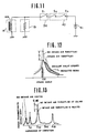
- the contacts S 2 , S 3 of the oil pressure switch 40 is electrically connected in series with the contact S, of the idle detecting switch (engine load detecting switch) 36 as shown in Fig. 11. Accordingly, electric current supply from a battery 41 to the solenoid actuator 14 and the sheathed heater 19 is controlled by these switches 36 and 40.
- the actuator solenoid 14b is energized and the sheathed heater 19 is supplied with electric current to be heated.
- the idle detecting switch 36 and/orthe oil pressure detecting switch 40 is switched OFF, so that the actuator solenoid 14b is not energized and sheathed heater 19 is not supplied with electric current.
- the throttle valve 9 is fully opened and intake air heating is not carried out by the sheathed heater 19.
- the engine can operate like a usual diesel engine which is not provided with the vibration suppression system according to the present invention, thereby obtaining a sufficient charging efficiency of intake air.
- the compression pressure within the combustion chamber is relatively lowered (as indicated by a solid line) as compared with in a conventional case (as indicated by a dotted tine) where intake air throttling is not carried out.
- the work done at compression stroke is decreased by an amount corresponding to lowered peak pressure, thereby suppressing engine speed fluctuation and torque fluctuation. This greatly lowers the vibrational force of the engine proper 1 and consequently reduces engine vibration.
- the character D indicates a range in which engine speed is lowered since torque is used for compression.
- the intake air throttling and the intake air heating are not carried out at engine deceleration or engine cranking even in a low load engine operating range, or at engine acceleration during vehicle starting even in a low engine speed operating range. This is because: at the engine deceleration in which the idle detecting switch 36 is switched ON and the oil pressure switch 40 is switched OFF, it is desirable to increase the work for compression in order to improve the effect of engine brake; at the engine cranking where the idle detecting switch 36 is switched ON and the oil pressure switch 40 is switched OFF due to too low engine lubrication oil pressure, it is required to raise the compression pressure in order to facilitate engine starting; and at the vehicle starting, a greater acceleration torque is required.
- a four cylinder engine has two explosion (compression) strokes per each engine revolution, vibrating engine one time at each explosion stroke, which constitutes 2nd harmonics of vibration which is indicated as "harmonics of vibration - 2nd" in Fig. 13.
- 2nd harmonics can be decreased by lowering compression pressure, while suppressing an increase of the harmonics of 0.5th, 1st and the like by heating intake air.
- intake air throttle valve 9 is fully closed at idling, intake air noise is damped, thereby achieving total reduction of noise and vibration.
- Fig. 14 shows an essential part of another embodiment according to the present invention, in which the means 18 for heating intake air or combustion air is formed in the engine proper 1.
- a ceramic housing 52 is disposed to almost fully surround a precombustion chamber (turbulence chamber) 51 formed in a cylinder head 50.
- a glow plug 53 forming part of the intake air heating means is disposed to project into the precombustion chamber 51.
- the glow plug 53 is arranged to be supplied with electric current to be heated simultaneously with the closure of the throttle valve 9 in the low engine speed and low engine load operating range such as idling. It will be appreciated that the temperature around the precombustion chamber 51 is maintained at a sufficiently high level because of a high specific heat of ceramic housing 52.
- Fig. 15 shows an essential part of a further embodiment according to the present invention, in which the means 18 for heating air includes an ignition ball section 61 formed projected into the precombustion chamber 51.
- the ignition ball section 61 is provided with a heater 60 embedded therein in order to heat the inside of the precombustion chamber 51.
- the ignition ball section 61 is formed integral with a ceramic holder 62 and located opposite to the fuel injector 39.
- the heater 60 has a first terminal 63 grounded to the cylinder head 50, and a second terminal 64 which is conductive to an electrode 65 inserted into the cylinder head 50.
- the electrode 65 is securely holded through an insulator 67 on a screwed plug 66 and in press contact with the terminal 64 through its contact terminal 68.
- heat generation from the heater 60 heats the ceramic holder 62 thereby to heat air within the precombustion chamber 51. This ensures stable combustion under the co-operative effect with the ignition of injected fuel by the high temperature ignition ball section 61 during fuel injection. Also in this embodiment, the heater 60 is so arranged as to generate heat together with the closure of the throttle valve 9 only at the low engine speed and low engine load operating range.
- the contact terminal 68 is formed of a bimetal 69 as shown in Fig. 16, in which when the temperature of the ceramic holder 62 is above a predetermined temperature, the contact terminal 68 deforms to interrupt the electrical connection between the terminal 64 and the electrode 65, thereby omitting unnecessary electricity supply while maintaining stable combustion.
- a relatively high intake vacuum is generated in the intake manifold 2 when the throttle valve is closed at idling or the like.
- the intake manifold 2 is preferably connected through a check valve 71 to a vacuum tank 72 by a conduit 73, so that vacuum can be accumulated in the vacuum tank 72 at every idling operation.
- the thus accumulated vacuum can actuate a vacuum actuator 74 for driving power brakes and power doors, thereby omitting or making small- sized a vacuum pump which has been conventionally necessary.
- intake air is largely throttled and simultaneously the intake air is positively heated in response to the low engine speed and low engine load operating condition.
- the temperature of compressed air is prevented from lowering to avoid irregular combustion and misfire. Consequently, engine vibration and noise can be greatly reduced while maintaining the stability of the engine operation.
Landscapes
- Engineering & Computer Science (AREA)
- Chemical & Material Sciences (AREA)
- Combustion & Propulsion (AREA)
- Mechanical Engineering (AREA)
- General Engineering & Computer Science (AREA)
- Control Of Throttle Valves Provided In The Intake System Or In The Exhaust System (AREA)
Claims (6)
Applications Claiming Priority (2)
| Application Number | Priority Date | Filing Date | Title |
|---|---|---|---|
| JP57048382A JPS58165547A (ja) | 1982-03-26 | 1982-03-26 | デイ−ゼルエンジンの振動低減装置 |
| JP48382/82 | 1982-03-26 |
Publications (2)
| Publication Number | Publication Date |
|---|---|
| EP0090345A1 EP0090345A1 (fr) | 1983-10-05 |
| EP0090345B1 true EP0090345B1 (fr) | 1987-02-04 |
Family
ID=12801757
Family Applications (1)
| Application Number | Title | Priority Date | Filing Date |
|---|---|---|---|
| EP83102899A Expired EP0090345B1 (fr) | 1982-03-26 | 1983-03-23 | Système de suppression des vibrations pour moteur diesel |
Country Status (4)
| Country | Link |
|---|---|
| US (1) | US4463721A (fr) |
| EP (1) | EP0090345B1 (fr) |
| JP (1) | JPS58165547A (fr) |
| DE (1) | DE3369718D1 (fr) |
Families Citing this family (23)
| Publication number | Priority date | Publication date | Assignee | Title |
|---|---|---|---|---|
| JPS60243330A (ja) * | 1984-05-18 | 1985-12-03 | Hitachi Ltd | エンジンの吸入空気量調整装置 |
| JPS611634U (ja) * | 1984-06-10 | 1986-01-08 | マツダ株式会社 | デイ−ゼルエンジンの吸気装置 |
| DE3444877A1 (de) * | 1984-08-14 | 1986-04-17 | Robert Bosch Gmbh, 7000 Stuttgart | Steuereinrichtung fuer eine brennkraftmaschine und verfahren zur steuerung von den brennraeumen einer selbstzuendenden brennkraftmaschine zugefuehrten gasen bestehend aus luft und abgasrueckfuehrmengen |
| JPS62165537A (ja) * | 1986-01-17 | 1987-07-22 | Komatsu Ltd | スパ−クアシストデイ−ゼルエンジンの吸気装置 |
| FR2605049B1 (fr) * | 1986-10-14 | 1991-07-12 | Renault | Dispositif d'admission d'air dans un moteur diesel et procedes de commande de ce dispositif. |
| GB2200949A (en) * | 1987-02-05 | 1988-08-17 | Lucas Ind Plc | I.C. engine pre-combustion chamber cup |
| US5040507A (en) * | 1990-03-07 | 1991-08-20 | Cummins Engine Company, Inc. | Method and device for variable idle speed control of an internal combustion engine |
| GB2255801A (en) * | 1991-05-13 | 1992-11-18 | Martyn Trevor Mercer | Diesel engine air intake control. |
| US5595164A (en) * | 1995-06-22 | 1997-01-21 | Phillips & Temro Industries Inc. | Low profile intake manifold heater |
| DE29514973U1 (de) * | 1995-09-20 | 1997-02-06 | Gehling, Johannes, 45289 Essen | Steuereinrichtung für eine dieselbetriebene Brennkraftmaschine und eine Ölheizung |
| US5887575A (en) * | 1996-01-04 | 1999-03-30 | Phillips & Temro Industries Inc. | Air intake heater with vertically oriented heating elements |
| US5743242A (en) * | 1996-01-04 | 1998-04-28 | Phillips & Temro Industries Inc. | Air intake heater with connector posts |
| EP1571325B1 (fr) * | 1998-04-15 | 2016-03-09 | Phillips & Temro Industries Inc. | Chauffage modulaire destiné à une admission d'air |
| US5988146A (en) * | 1998-04-15 | 1999-11-23 | Phillips & Temro Industries Inc. | Modular air intake heater |
| US5992399A (en) * | 1998-04-15 | 1999-11-30 | Phillips & Temro Industries Inc. | Modular air intake heater |
| US6031204A (en) * | 1998-12-10 | 2000-02-29 | Phillips & Temro Industries Inc. | Drop-in air heater for an engine with heater support frame having prongs |
| US6040557A (en) * | 1998-12-10 | 2000-03-21 | Phillips & Temro Industries Inc. | Drop-in air heater for an engine with heater support frame having prongs engaging heater holders |
| DE10214166A1 (de) * | 2002-03-28 | 2003-10-23 | David & Baader Gmbh | Heizflansch, insbesondere zum Vorwärmen von Luft in einer Ansaugleitung einer Brennkraftmaschine |
| DE502005005799D1 (de) * | 2005-01-07 | 2008-12-11 | Dbk David & Baader Gmbh | Heinzflansch mit geometrisch stabiler Struktur |
| US7779812B2 (en) * | 2008-07-15 | 2010-08-24 | Ford Global Technologies, Llc | Vehicle stability and surge control |
| US20150114339A1 (en) * | 2013-10-31 | 2015-04-30 | Delphi Technologies, Inc. | Cold start strategy and system for gasoline direct injection compression ignition engine |
| US10480366B2 (en) * | 2017-09-20 | 2019-11-19 | Fca Us Llc | Throttled PCV system for an engine |
| CN117418974B (zh) * | 2023-12-18 | 2024-04-16 | 潍柴动力股份有限公司 | 一种发动机进气装置、节流阀控制方法及相关设备 |
Citations (4)
| Publication number | Priority date | Publication date | Assignee | Title |
|---|---|---|---|---|
| US4058101A (en) * | 1975-07-08 | 1977-11-15 | Nippondenso Co., Ltd. | Control apparatus for diesel engine |
| JPS5676158U (fr) * | 1979-11-16 | 1981-06-22 | ||
| JPS5683535A (en) * | 1979-12-08 | 1981-07-08 | Mazda Motor Corp | Shutter device for intake of diesel engine |
| JPS56101032A (en) * | 1980-01-16 | 1981-08-13 | Mazda Motor Corp | Intake system for diesel engine |
Family Cites Families (11)
| Publication number | Priority date | Publication date | Assignee | Title |
|---|---|---|---|---|
| US1211087A (en) * | 1916-03-13 | 1917-01-02 | Erving D Clark | Means for converting kerosene-oil into explosive gas for internal-combustion engines. |
| US2139777A (en) * | 1937-12-09 | 1938-12-13 | Skok Alois | Electric and automatic fuel vaporizer |
| US2414296A (en) * | 1943-10-13 | 1947-01-14 | Garrett Corp Aires Mfg Company | Anti-icing control for engine systems |
| US2664868A (en) * | 1951-06-13 | 1954-01-05 | Gen Motors Corp | Engine governor |
| US3157167A (en) * | 1961-02-13 | 1964-11-17 | Walker Brooks | Varisable maximum throttle position for engine |
| CH457035A (de) * | 1966-10-27 | 1968-05-31 | Maschf Augsburg Nuernberg Ag | Vorrichtung zur Verminderung der Geräusche in der Ansaugleitung eines Dieselmotors |
| FR2323889A3 (fr) * | 1974-01-09 | 1977-04-08 | Brochot Daniel | Perfectionnements aux moteurs diesel |
| US4391246A (en) * | 1979-05-07 | 1983-07-05 | Honda Giken Kogyo Kabushiki Kaisha | Throttle opener device for vehicle engines |
| US4354464A (en) * | 1979-12-08 | 1982-10-19 | Toyo Kogyo Co., Ltd. | Air intake arrangement for diesel engine |
| US4354465A (en) * | 1980-07-08 | 1982-10-19 | Isuzu Motors Ltd. | Diesel throttle valve control system |
| JPS58165560A (ja) * | 1982-03-26 | 1983-09-30 | Nissan Motor Co Ltd | デイ−ゼルエンジンの振動低減装置 |
-
1982
- 1982-03-26 JP JP57048382A patent/JPS58165547A/ja active Pending
-
1983
- 1983-03-22 US US06/477,742 patent/US4463721A/en not_active Expired - Fee Related
- 1983-03-23 EP EP83102899A patent/EP0090345B1/fr not_active Expired
- 1983-03-23 DE DE8383102899T patent/DE3369718D1/de not_active Expired
Patent Citations (4)
| Publication number | Priority date | Publication date | Assignee | Title |
|---|---|---|---|---|
| US4058101A (en) * | 1975-07-08 | 1977-11-15 | Nippondenso Co., Ltd. | Control apparatus for diesel engine |
| JPS5676158U (fr) * | 1979-11-16 | 1981-06-22 | ||
| JPS5683535A (en) * | 1979-12-08 | 1981-07-08 | Mazda Motor Corp | Shutter device for intake of diesel engine |
| JPS56101032A (en) * | 1980-01-16 | 1981-08-13 | Mazda Motor Corp | Intake system for diesel engine |
Also Published As
| Publication number | Publication date |
|---|---|
| EP0090345A1 (fr) | 1983-10-05 |
| JPS58165547A (ja) | 1983-09-30 |
| US4463721A (en) | 1984-08-07 |
| DE3369718D1 (en) | 1987-03-12 |
Similar Documents
| Publication | Publication Date | Title |
|---|---|---|
| EP0090345B1 (fr) | Système de suppression des vibrations pour moteur diesel | |
| EP0090313B1 (fr) | Système de suppression des vibrations pour moteur diesel | |
| US3941105A (en) | Exhaust gas recirculation for three-valve engine | |
| US4480620A (en) | Fuel supply system of internal combustion engine | |
| KR890000749B1 (ko) | 디젤엔진의 흡기장치 | |
| KR20010099743A (ko) | 내연기관 내의 연소과정을 제어하는 방법, 그리고 엔진밸브를 조절하기 위한 수단을 구비한 엔진 | |
| WO2000028198A1 (fr) | Procede de commande du procede de combustion dans un moteur a combustion interne, et moteur equipe de moyens destines a faire varier le rapport de compression effectif des cylindres | |
| JPH0637870B2 (ja) | 過給機付エンジンの点火装置 | |
| US4237828A (en) | Method of controlling an internal combustion engine | |
| US4327691A (en) | Air-fuel-mixture forming device for spark ignition internal combustion engines | |
| US4365605A (en) | Apparatus for improving the acceleration of an internal combustion engine driven with an exhaust turbocharger | |
| US3745984A (en) | Purge control valve and system | |
| US4014301A (en) | Externally ignited internal combustion engine with ignition chamber | |
| US5582149A (en) | Ignition timing control for engine | |
| US4231339A (en) | Control device for exhaust gas recycled internal combustion engine | |
| US4986239A (en) | Ignition timing controller for internal combustion engine | |
| US7047937B2 (en) | Internal combustion engine | |
| US4243005A (en) | Ignition system in dual spark plug ignition engine with EGR system | |
| US4955831A (en) | Ignition timing control system for outboard engine | |
| US5673667A (en) | Engine knock control | |
| US4068634A (en) | Control system for ignition timing of engine | |
| US3977383A (en) | Engine intake manifold | |
| US4848287A (en) | Method and system for controlling spark ignition in internal combustion engine | |
| US4784100A (en) | Electrically controlled engine ignition system for power boost and fuel economy | |
| US3577963A (en) | Control for internal combustion engines |
Legal Events
| Date | Code | Title | Description |
|---|---|---|---|
| PUAI | Public reference made under article 153(3) epc to a published international application that has entered the european phase |
Free format text: ORIGINAL CODE: 0009012 |
|
| 17P | Request for examination filed |
Effective date: 19830323 |
|
| AK | Designated contracting states |
Designated state(s): DE FR GB |
|
| RAP1 | Party data changed (applicant data changed or rights of an application transferred) |
Owner name: NISSAN MOTOR CO., LTD. |
|
| GRAA | (expected) grant |
Free format text: ORIGINAL CODE: 0009210 |
|
| AK | Designated contracting states |
Kind code of ref document: B1 Designated state(s): DE FR GB |
|
| PG25 | Lapsed in a contracting state [announced via postgrant information from national office to epo] |
Ref country code: FR Free format text: THE PATENT HAS BEEN ANNULLED BY A DECISION OF A NATIONAL AUTHORITY Effective date: 19870204 |
|
| REF | Corresponds to: |
Ref document number: 3369718 Country of ref document: DE Date of ref document: 19870312 |
|
| EN | Fr: translation not filed | ||
| PLBE | No opposition filed within time limit |
Free format text: ORIGINAL CODE: 0009261 |
|
| STAA | Information on the status of an ep patent application or granted ep patent |
Free format text: STATUS: NO OPPOSITION FILED WITHIN TIME LIMIT |
|
| 26N | No opposition filed | ||
| PG25 | Lapsed in a contracting state [announced via postgrant information from national office to epo] |
Ref country code: GB Free format text: LAPSE BECAUSE OF NON-PAYMENT OF DUE FEES Effective date: 19881122 |
|
| GBPC | Gb: european patent ceased through non-payment of renewal fee | ||
| PGFP | Annual fee paid to national office [announced via postgrant information from national office to epo] |
Ref country code: DE Payment date: 19890428 Year of fee payment: 7 |
|
| PG25 | Lapsed in a contracting state [announced via postgrant information from national office to epo] |
Ref country code: DE Effective date: 19901201 |