EP0090377A2 - Système d'identification des empreintes digitales - Google Patents
Système d'identification des empreintes digitales Download PDFInfo
- Publication number
- EP0090377A2 EP0090377A2 EP83102997A EP83102997A EP0090377A2 EP 0090377 A2 EP0090377 A2 EP 0090377A2 EP 83102997 A EP83102997 A EP 83102997A EP 83102997 A EP83102997 A EP 83102997A EP 0090377 A2 EP0090377 A2 EP 0090377A2
- Authority
- EP
- European Patent Office
- Prior art keywords
- minutia
- anomalies
- fingerprint
- pixels
- candidates
- Prior art date
- Legal status (The legal status is an assumption and is not a legal conclusion. Google has not performed a legal analysis and makes no representation as to the accuracy of the status listed.)
- Granted
Links
Images



Classifications
-
- G—PHYSICS
- G06—COMPUTING OR CALCULATING; COUNTING
- G06V—IMAGE OR VIDEO RECOGNITION OR UNDERSTANDING
- G06V10/00—Arrangements for image or video recognition or understanding
- G06V10/20—Image preprocessing
-
- G—PHYSICS
- G06—COMPUTING OR CALCULATING; COUNTING
- G06V—IMAGE OR VIDEO RECOGNITION OR UNDERSTANDING
- G06V10/00—Arrangements for image or video recognition or understanding
- G06V10/20—Image preprocessing
- G06V10/30—Noise filtering
-
- G—PHYSICS
- G06—COMPUTING OR CALCULATING; COUNTING
- G06V—IMAGE OR VIDEO RECOGNITION OR UNDERSTANDING
- G06V10/00—Arrangements for image or video recognition or understanding
- G06V10/40—Extraction of image or video features
-
- G—PHYSICS
- G06—COMPUTING OR CALCULATING; COUNTING
- G06V—IMAGE OR VIDEO RECOGNITION OR UNDERSTANDING
- G06V10/00—Arrangements for image or video recognition or understanding
- G06V10/70—Arrangements for image or video recognition or understanding using pattern recognition or machine learning
-
- G—PHYSICS
- G06—COMPUTING OR CALCULATING; COUNTING
- G06V—IMAGE OR VIDEO RECOGNITION OR UNDERSTANDING
- G06V10/00—Arrangements for image or video recognition or understanding
- G06V10/70—Arrangements for image or video recognition or understanding using pattern recognition or machine learning
- G06V10/74—Image or video pattern matching; Proximity measures in feature spaces
- G06V10/75—Organisation of the matching processes, e.g. simultaneous or sequential comparisons of image or video features; Coarse-fine approaches, e.g. multi-scale approaches; using context analysis; Selection of dictionaries
-
- G—PHYSICS
- G06—COMPUTING OR CALCULATING; COUNTING
- G06V—IMAGE OR VIDEO RECOGNITION OR UNDERSTANDING
- G06V40/00—Recognition of biometric, human-related or animal-related patterns in image or video data
- G06V40/10—Human or animal bodies, e.g. vehicle occupants or pedestrians; Body parts, e.g. hands
- G06V40/12—Fingerprints or palmprints
- G06V40/1347—Preprocessing; Feature extraction
-
- G—PHYSICS
- G06—COMPUTING OR CALCULATING; COUNTING
- G06V—IMAGE OR VIDEO RECOGNITION OR UNDERSTANDING
- G06V40/00—Recognition of biometric, human-related or animal-related patterns in image or video data
- G06V40/10—Human or animal bodies, e.g. vehicle occupants or pedestrians; Body parts, e.g. hands
- G06V40/12—Fingerprints or palmprints
- G06V40/1365—Matching; Classification
-
- G—PHYSICS
- G07—CHECKING-DEVICES
- G07C—TIME OR ATTENDANCE REGISTERS; REGISTERING OR INDICATING THE WORKING OF MACHINES; GENERATING RANDOM NUMBERS; VOTING OR LOTTERY APPARATUS; ARRANGEMENTS, SYSTEMS OR APPARATUS FOR CHECKING NOT PROVIDED FOR ELSEWHERE
- G07C9/00—Individual registration on entry or exit
- G07C9/30—Individual registration on entry or exit not involving the use of a pass
- G07C9/32—Individual registration on entry or exit not involving the use of a pass in combination with an identity check
- G07C9/37—Individual registration on entry or exit not involving the use of a pass in combination with an identity check using biometric data, e.g. fingerprints, iris scans or voice recognition
Definitions
- This invention relates to an apparatus and a method of identifying and classifying the minutia of a fingerprint for the purposes of enrollment to establish a reference file and verification of a subject's identity against his or her reference files.
- Fingerprints are uniquely identified by the set of minutia characteristic of the fingerprint. These minutia are two standard elements; line endings and line bifurcations.
- a fingerprint can be analyzed either in terms of its ridges or its valleys. In either case, there will be endings and bifurcations.
- the ridge analysis of a fingerprint will be in terms of ridge endings and ridge bifurcations while a valley analysis of a fingerprint will be in terms of valley endings and valley bifurcations.
- a valley ending is defined by a ridge bifurcation and a ridge ending is defined by a valley bifurcation.
- Type I and Type II errors There are two types of errors which it is the object of this invention to minimize. These errors will be termed herein Type I and Type II errors.
- Type I error is one where the individual who is supposed to have access is rejected.
- a Type II error is one in which an individual who is supposed to be denied access is passed.
- a Type I error can be considered a false negative and a Type II error can be considered a false positive.
- Type I errors indicate system sensitivity in that the system is sensitive to the correspondence between an input fingerprint and the corresponding enrolled fingerprint. Thus, in a high percentage of cases, the system will positively identify the individual whose fingerprint is being presented.
- low Type II errors indicate system specificity in that the identification is specific to the individual involved so that the probability is low that an input fingerprint will be identified as corresponding to an enrolled fingerprint of another individual.
- the technique of this invention involves a series of steps on an input fingerprint image.
- the image is derived from an optical scan of the finger or fingerprint and the modulated scan has preferably been mechanically-optically filtered to remove the higher frequency spatial components of the image and thus eliminate some of the noise.
- the input image is presented as a field of pixels.
- a set of templates are scanned across the input image to identify all possible line endings and bifurcations. This identifies most line discontinuities and most line branching. In this fashion, an extensive set of anomalies is initially identified.
- a simple geometric analysis is made of a predetermined zone around each identified anomaly.
- This geometric analysis is directed to the structure of minutia and, in particular, to the fact that on the sides of each good minutia there are substantial zones of the contrasting value.
- Those anomalies which meet this geometric criteria are passed on as minutia candidates for further processing while the bulk of the anomalies, typically 60% to 80%, are eliminated.
- This geometric criteria is selected to have a low rejection error although obviously it has a moderately high acceptance error. But it quickly and inexpensively provides a substantial reduction in the number of anomalies so that the subsequent more time consuming and expensive steps will be applied to a substantially reduced number of anomalies.
- phase three identifies noisy subfields and quickly eliminates a large portion of the noise while eliminating few of the minutia.
- Phase four makes a detailed analysis of paired minutia candidates to identify relationships which are typical of the noise structure in a fingerprint.
- a fifth phase of the processing identifies the angle of the minutia by comparing each minutia against a series of templates.
- a skeletal version of the minutias is employed to standardize this comparison.
- a sixth phase of the processing involves establishing a reduced file of minutia representing the most stable and repeatable minutia so as to provide a final reference file of minutia no greater than 20 minutia and no less than 7 minutia. Limiting the number of minutia speeds up the verification process.
- the input fingerprint is removed and reapplied a number of times to provide a plurality of scans.
- the minutia determined by the fifth phase of processing is compared with the minutia developed or identified in the initial scan. Based on the frequency of repetition of corresponding minutia, a final reference file is provided consisting of those minutia which are repeated most frequently.
- the verification mode of the invention employs, as much as possible, the same steps as are employed in enrollments so that there is substantial congruence between the enrollment mode and the verification mode in order to compensate for any biases due to the processing technique.
- the sixth phase of processing is a comparison of the input fingerprint image against the final reference file having a relatively limited number of minutia.
- a typical fingerprint may be detected or represented in any one of a number of known ways.
- One such way is illustrated by the optical scanning techniques disclosed in United States Patent No. 4,322,163, which is incorporated herein by reference.
- This optical scan provides a light beam which is modultaed by the ridges and valleys of the fingerprint.
- the modulated light beam is applied to an array of charge coupled devices to provide a field of signals each having either a high value or low value representing the fingerprint.
- the fingerprint is optically scanned to provide a modulated beam.
- the array may be a line of about two hundred elements which are subjected to the modulated beam and interrogated electronically at a predetermined rate.
- a set of data constituting a field of individual data points or pixels.
- this field is 192 by 254 pixels thus providing 48,768 pixels.
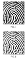
- the portion of the fingerprint shown in FIG. 1 is illustrated in FIG. 2 by a field of pixels.
- Each data point is referred to herein as a pixel.
- a pixel there is a set of about 48,000 pixels having either a "one" value or a "zero" value to represent the fingerprint.
- the term pixel refers to the smallest resolved element in a picture system.
- the pixels having a "one” value are represented by small shaded squares and the "zero" value pixels by small blank squares.
- the shaded pixels can be considered as corresponding to a ridge input and the blank pixels as corresponding to a valley input.
- FIGS. 1 and 2 illustrate a typical ridge line ending 12 and a typical ridge bifurcation 14.
- the minutia constitute the identifying characteristics of the fingerprint for the purposes of initially enrolling the fingerprint as one of a set of fingerprint data in the system or, subsequently, for identifying an input fingerprint as corresponding to one of those enrolled in the system.
- FIG. 3 represents a series of thirty-seven templates which are used to identify what are somewhat arbitrarily termed herein anomalies in the set of pixels representing the fingerprint.
- Each of the FIG. 3 templates is a set of 3 x 8 pixels having the contrasting values shown.
- ridge lines could be represented by dark pixels or by light pixels as long as the valleys are of the other value.
- each of the thirty-seven templates shown in FIG. 3 is scanned over the fingerprint field and whenever any of these templates matches any sub-field within the field of the fingerprint, that match is identified and the sub-field appropriately tagged as an anomaly.
- the templates shown tend to identify line endings having an upward direction.
- an additional thirty-seven templates are provided corresponding to the FIG. 3 templates rotated ' 180 degrees.
- the templates shown in FIG. 3 is reversed in pixel value to provide an identical, but reversed field, set of templates.
- These line bifurcation templates are not only the thirty-seven corresponding to the reverse field of those shown in FIG. 3 but are also an additional thirty-seven congruent to the first thirty-seven except rotated 180 degrees. Thus one hundred forty eight templates are used. This phase one screening tags each anomaly as either a line ending or a line bifurcation.
- the one.hundred forty eight templates represented by FIG. 3 tend to pick out ridge line endings and ridge bifurcations having upward and downward directions.
- the anomalies having left and right orientations are picked out by rotating the image 90° and repeating this process.
- the analysis of the rotated image occurs after all phases of the processing of the non-rotated image is completed.
- Phase one is a very rough screen and may produce in the order of five hundred to one thousand anomalies.
- This phase one approach looks at a discontinuity criteria and identifies any 3 x 8 sub-field which has a discontinuity as an anomaly to be looked at to determine if it is a candidate for a minutia. Because it identifies almost any discontinuity, this rough screen has a very low rejection of correct minutia and a high noise acceptance. But, it provides a simple, quick, and easy to implement screen to establish a set of anomalies for more detailed analysis.
- the phase one processing using the type of templates illustrated in FIG. 3 provides information concerning the type of anomaly (line ending or bifurcation) , the curvature and thickness of the anomaly, and the relative position of each anomaly in the field being scanned.
- the line ending anomalies in the first row of FIG. 3 are all relatively thin anomalies with a high curvature compared with those in the fourth and fifth rows.
- a sub-field center pixel C is selected, on a predetermined basis, as the identifying end point pixel from which further processing, as described below, is undertaken.
- the center pixel C for a line ending is the same center pixel for the complementary line bifurcation.
- the second phase of processing is a simple, powerful technique directed to a structural examination in a very small area and eliminates most of the anomalies, therefore providing a set of minutia candidates.
- Concatenation of phase one and phase two processing may eliminate as much as 80% of the anomalies and thereby produce a set of about two hundred minutia candidates.
- the phase two approach is based on the observation that stable minutia have substantial adjacent areas of the opposite value. That is, a ridge line ending minutia is a ridge line segment having substantial thickness surrounded on three sides by a valley having substantial thickness. Similarly, a ridge bifurcation is a valley line ending segment of meaningful thickness surrounded on three sides by a ridge having meaningful thickness. Thus, in both cases there is a straight line segment having a particular value and having meaningful thickness for that value which is surrounded on three sides by a zone of the other value having meaningful thickness.
- a first part of this second phase is a border edit to eliminate what is essentially an unstable pixel zone along the boundary of the image. All phase one anomolies which have their center pixel C within this border zone are eliminated.
- this border zone has a width that is 24 pixels along the bottom, 16 pixels along the left, 8 pixels along the top and 8 pixels along the right. This reduction of the effective area to be further processed by about twenty percent substantially increases the speed of the process and reduces the rate at which anomolies are erroneously identified as minutia while eliminating very few good useful minutia.
- the larger zone along the bottom and left is dictated by observation and probably reflects the effects of scan initialization.
- the center pixel C for each of the anomalies selected from phase one provides a point from which a count is made to a transition zone on a first side of the anomaly and then a count is made to a transition zone on the other side of the anomaly. If the transition zone fails to show a predetermined continuity, then the anomaly is rejected.
- the line ending pixel C may be designated as the pixel (x, y).
- the pixel (x + 1) , (y + 1) is identified.
- a count of pixels to the right of (x + 1), (y + 1) is made to the first light to dark transition zone. That count is designated as Ll.
- a similar count to the right to the first light to dark transition zone from (x + 1) , (y - 1) is made and that number designated as L2. If the absolute value of the difference between Ll and L2 is greater than five, then the anomaly is rejected as a minutia candidate.
- a similar test is made by counting pixels to the left to the first light to dark transition zone. A count is made to the left from the pixel (x - 1), (y + 1) and from. the pixel (x - 1), (y - 1) respectively. Again, if the absolute value of the difference between those two counts is greater than five, the anomaly is rejected.
- this phase two technique has a low rejection error in that it rejects few good minutia. However it has a fairly high acceptance error in that it passes a substantial amount of noise. But the acceptance error is substantially better than provided by the phase one rough screening technique.
- the third phase of processing is another simple technique which recognizes that the structure of a fingerprint includes noisy local areas and that elimination of everything in such an area as a minutia candidate will greatly reduce the amount of subsequent processing with minimal loss of useful information.
- this noise rejection quick-out technique a subfield of 21 x 23 pixels is erected around each minutia candidate that emerges from the phase two processing.
- the anomaly end point pixel C is the center of the 21 x 23 pixel sub-field.
- a count is made of the number of phase one anomalies in the 21 x 23 pixel box. If that count is greater than some predetermined number, then every minutia candidate in that box, including the center candidate, is eliminated from further analysis. This provides a reduced set of minutia candidates.
- the predetermined number has been as high as twenty-nine in one embodiment and as low as twelve in another embodiment. A higher number is preferred to assure enrollment of as much of the population as possible. A lower number is preferable to speed up processing in verification. The optimum number is a partial function of the criteria used in the rest of the processing.
- Each minutia candidate that emerges from the phase three processing is subject to a substantially more detailed processing which involves analysis within the sub-field of 21 x 23 pixels erected around each minutia candidate.
- This box of 21 - 23 pixels provides a sufficient field so that a comparison can be made between the minutia candidate and other closely associated anomalies. Certain relationships can be identified which are known to indicate structures that are not classical minutia and thus, must be rejected as noise.
- FIGS. 5 and 6 represent in somewhat idealized and schematic form, the kinds of structural relationships which are identified in the phase four processing and which result in the elimination of minutia candidates to provide a set of minutia.
- FIGS. 5A through 5D and FIG. 5G represent those bridge and crack type of situations in which the candidate minutia being tested (represented by an end point pixel C at the center of the box) is rejected because of its close proximinity to another anomaly.
- the minutia candidate at the center of the box is being compared with those anomalies identified in the first phase of processing. This close proximity indicates either a break in what is otherwise a continuous ridge line or a bridging over between two adjacent continuous ridge lines. Such breaks and bridges are unstable and thus constitute noise and cannot be usefully used to indicate or represent classical minutia.
- FIGS. 5E, 5F, 5H and 51 represent situations in which the minutia candidate (represented by its "end point" pixel C at the center of the box) is carried forward as a candidate even though there are nearby anomalies.
- the structural relationship between the center minutia candidate and the adjacent anomalies are such as to indicate that the adjacent anomalies arise out of cracks, bridges, ripples, holes, etc. which are substantially part of a continuing ridge line.
- the adjacent anomalies are noise because they cannot be relied upon and thus are not classical minutia.
- the center candidate minutia stands on its own as a likely minutia.
- the center minutia candidate is not rejected.
- the center minutia candidate is rejected where it is paired with another adjacent anomaly and that pairing indicates a break in what otherwise is a continuous ridge line or a bridge between what otherwise is a continuous ridge line.
- the break in the ridge 40 serves to generate the line ending minutia candidate represented by the end point pixel 40c. But, because of the immediately adjacent anomaly represented by the end point pixel 41, it is clear that these anomalies (represented by 40c and 41) do not represent line endings, but rather a break in the ridge 40.
- the bifurcation minutia candidate represented by the pixel 44c is close to the line ending anomaly represented by the end point pixel 43. The proximity of the pair is such as to indicate that the minutia candidate 44 is not a bifurcation, but rather has been generated by an unstable break in what should be treated as a ridge continuity.
- 5C represents a situation in which two ridges 45a, 45b pass close to one another and in which a bridging over between them occurs. But, because the bridge is not sufficiently thick and long, it does not represent a stable configuration, thus is noise and cannot be treated as a minutia.
- the proximity of the anomaly pair represented by end point pixels 45c and 46 indicates that the minutia candidate 45 is not a stable minutia.
- the kind of break shown schematically in FIG. 5D is a variation on the one shown in FIG. 5A, in which the ridge line 47 has a break that is represented by two anomalies having end point pixels 47c and 48.
- FIGS. 5E, 5F, 5H and 51 represent a number of different types of situations in which paired minutia candidates are observed displaced from the box center pixel C representing the minutia candidate under consideration. Because they are paired they do not result in the rejection of the center box minutia candidate.
- FIG. 5E illustrates a ripple situation (represented by the anomalies having end points 50a, 50b), where the ripple is displaced from the candidate bifurcation minutia 49. This simply represents the fact that a ridge line may have a ripple or wavy segment.
- the cracks in FIG. 5F represent spacings in the ridge line 51 which are sufficiently narrow so that they are likely to be unstable, and in any case do not detract from the overall ridge continuity.
- FIG. 5F A comparison of FIG. 5F and FIG. 5A may be somewhat instructive.
- Pixels 52a, 52b in FIG. 5F are analogous to the pixels 40 and 41 in FIG. 5A. In both cases they represent a crack, which is likely to be unstable, and which is certainly not typical of a classic line ending minutia.
- the result is the elimination of a minutia candidate because the end pixel 40c of that candidate is part of the pair.
- FIG. ' 5F the bifurcation minutia candidate under consideration is not eliminated because it is not part of the pair. But the two anomalies represented by the pair 51a, 51b have been or will be eliminated as minutia candidates.
- the classic bridge shown in FIG. 5G represents an unstable bifurcation arrangement in which the ridge 53 bifurcation represented by the center pixel 53C is rejected as a minutia because of the closely located paired anomaly 53d.
- the existance of the pair of adjacent anomalies, represented by the end point pixels 54a and 54b do not override that indication of instability because elimination of the pair 54a, 54b still leaves the pair 53c, 53d.
- FIG. 5G situation is similar to the FIG. 5C modified bridge situation.
- the ridge 55 does have a line ending represented by the pixel 55c and that the adjacent paired anomalies 56a, 56b and 57a, 57b represent minor holes which should be disregarded in what is otherwise continuous ridge line structure.
- the kissing ridge situation shown in FIG. 5I and the modified bridge arrangement shown in FIG. 5C are substantially similar in that they both represent adjacent ridges which touch one another at one point, normally an unstable configuration, but which certainly is not a classical minutia.
- the ridge 59 is a line ending represented by the pixel 59c.
- the adjacent paired anomalies represented by pixels 60a and 60b indicate that the instability is represented by the pair 60a and 60b and- is not associated with the line ending 59c. '
- positionally closely associated paired anomalies represent the fact that there is no minutia candidate associated with either member of the pair of anomalies.
- the paired, rejected anomalies are not only close to one another but have either opposite curvatures or are of a different type.
- FIGS. 5A through 5D and 5G this results in the elimination of the anomaly which is represented by the minutia candidate having the center pixel C because it is one of the paired anomalies.
- the paired anomalies are displaced from the center pixel C and thus the corresponding minutia candidate is retained because it is not one of the paired anomalies.
- the anomalies 61c and 62 in FIG. 6 are sufficiently spaced from one another so that they clearly do not represent a ripple and thus do not fall under any rule relating to the elimination of closely paired anomalies.
- the rule is: after all paired anomalies are eliminated, if there are two or more anomalies left in addition to the minutia candidate anomaly at the center, then the minutia candidate is dropped.
- FIG. 6 represents a situation where there is only one additional anomaly and thus is not eliminated under that rule.
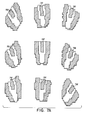
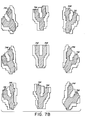
- FIGS. 7A and 7B illustrate the set of nine line ending and nine bifurcation templates covering 90 0 of image angle, against which each minutia is correlated to provide an angle identification to within 11.25°.
- FIGS 7A and 7B as in all the FIGS. herein, the convention employed is to shade in those pixels which represent a ridge line under consideration. Obviously, in all of the FIGS. the value of the pixel could be reversed and the identical analysis made. Furthermore, as indicated earlier, the analysis can be either ridge analysis or valley analysis.
- the zones marked 72 each represent a ridge line ending minutia having a different angle in increments of 11.25 0 .
- the zones 74 represent a ridge bifurcation minutia each having a different angle in increments of 11.25°.
- the eighteen templates shown in FIGS. 7A and 7B are supplemented by an additional eighteen templates identical in configuration except rotated 180 0 from those shown in the drawings.
- the input minutia derived from the "vertical" axis analysis in the earlier phases of processing are processed separately from the input minutia derived from the "horizontal" axis analysis throughout the enrollment and verification modes. The analysis along one axis is first completed and then the image is rotated to permit identical analysis along the other axis.
- the input bifurcation or line ending minutia has to be normalized in thickness in order to use these FIG. 7 templates so that the templates will be equally effective with fingerprints where the ridges are relatively thick or relatively thin.
- a skeletal ridge line is employed.
- the skeletal ridge line is achieved by reducing the ridge line to one pixel wide.
- the center of gravity of each horizontal row of pixels within a ridge line is employed. Thus if a ridge line is three, five, or any odd number of pixels wide, the center pixel is the one that is selected to represent the ridge at that point for the purpose of this FIG. 7 template angular analysis.
- a consistant rule of choosing the pixel to the right of center may be employed.
- This skeletal minutia is then overlaid on each of the templates shown and the number of skeletal pixels which fall within the template zone 74 (where bifurcations are being tested) or the template zone 72 (where line endings are being tested) are counted.
- the minutia is then tagged with an angle that is determined by the template match where the maximum pixel count is obtained.
- the normalization of the minutia substantially eliminates the uncertainity of FIG. 7 template angle identification.
- this skeletal arrangement which is provided to effect normalization, creates an enhanced sensitivity to positional changes.
- the movement of the skeletal minutia to the left or right by only a pixel or two can result in the difference between the minutia falling primarily within a given template or outside of that template.
- This sensitivity to position has to be recognized in connection with this routine for scanning the FIG. 7 templates over the normalized minutia.
- the preferred scan routine involves the following procedure on a template by template basis. First, the center of gravity of the template is caused to coincide with the center of gravity of the non-normalized minutia. The degree of correlation between the normalized (skeletal) minutia and the template so placed is determined. The template is then displaced (but not rotated) in increments of one pixel in various directions and the degree of correlation between the template and the skeletal minutia is determined for each displacement position. That position which provides the greatest correlation is deemed to be the correlation figure between that template and the minutia involved. The same routine is repeated for each template on each minutia under investigation. The template where the correlation is greatest is the one which is used to designate the angle of the minutia. fifth phase
- the final reference file constitutes a subset of the minutia identified by the five stages of processing indicated above.
- a typical figerprint may have forty to fifty fairly good repeatable classical minutia. Some poor quality fingerprints have less. Some fingerprints have more.
- a file reduction routine is undertaken which reduces the number of minutia in the reference file to approximately ten to fifteen minutia.
- One important consequence of this reduced set of reference file minutia is that the time required for the verification procedure is substantially reduced. To obtain this increased throughput, without increasing Type I or Type II identification errors, it is necessary to select the minutia to be kept in the final reference file according to certain procedures.
- an initial reference file is established by going through the processing phases one through five set forth above. Then a set of multiple scan steps are undertaken as set forth below. After each scan, the minutia detected are compared against the initial reference file. A final reference file of minutia is established based on those minutia picked up most frequently during the multiple scans. More particularly, the following steps are taken.
- This initial file is the result of the first scan in the enrollment process.
- This initial reference file typically has forty to fifty minutia per axis although the number of minutia may occasionally be as high as one hundred and as low as twenty or even less. In one embodiment, the number of minutia points per axis was arbitrarily set at fifty for the initial reference file.
- Those minutia selected for the preliminary reference file are those which appear in each of a predetermined number of subsequent scans.
- the subject re- applies the finger to the platen an additional six times
- the processing phases one through five are undertaken each time the finger is reapplied to the platen.
- Those minutia from the initial reference file which fail to be identified a requisite number of times in these multiple verification scans are then dropped from the reference file. This provides a verification technique in enrollment to provide a purged or limited set of minutia. In this fashion, the most stable minutia are selected.
- each of those scans two through seven the following difference plane analysis is made to identify the minutia from the scan involved with corresponding minutia from the initial reference file.
- a 96 x 96 pixel box is erected around each of the minutia identified in the initial scan.
- each of the minutia identified in that subsequent scan is positionally correlated against the minutia from the initial scan which is at the center of the box. This positional correlation is between the end point pixel C of each of the subject minutia in the box and the end point pixel C of the reference minutia at the center of the box.
- FIG. 8 shows a possible difference plane.
- each initial reference file minutia there are typically between forty and fifty minutia in the initial reference file.
- Each of these reference file minutia has an end point pixel C with position characteristic x and y.
- the subject minutia within each 96 x 96 box are compared with the reference file minutia at the center of the box. Specifically the algebraic difference between the x values of the two minutia being compared and the algebraic difference between the y values is plotted as a data point in an x, y difference plane such as shown in FIG. 8
- points in the difference plane are generated by taking each subject minutia within the 96 x 96 box that is within plus or minus one angular increment from the reference minutia point/the center of the box and comparing that subset of subject points against the center reference point to generate difference points on the difference plane.
- the difference plane is created by the addition of all the difference points from all the reference minutia centered boxes in a given scan.
- the difference plane will show a cluster of difference points offset from the center.
- the reason why the cluster is offset is that on each successive input of a finger on the platen, there is likely to be a displacement of the fingerprint along both the x and y axis from that fingerprint's input location when establishing the initial reference file. That cluster represents those reference minutia/subject minutia comparisons in which the two minutia being compared are likely to be corresponding minutia.
- a window of 16 x 16 pixels is scanned across the difference array to a position within which a maximum number of difference points occurs.
- a window 80 is shown in FIG. 8. Each point within the window is deemed to be a valid identification of the reference file minutia responsible for the point. For each of the scans two through seven, each valid identification is tallied against the corresponding reference file minutia.
- this cluster seeker window 80 is centered successively at each of the difference points in the plane.
- the difference point in the plane on which the window is centered when the window encompasses the greatest number of points need not necessarily be the location which has the greatest number of points.
- the window 80 is centered on a difference plane location that is two spaces removed from the space in the plane where there are eight difference points located.
- Each of the initial reference file minutia which is so identified in at least five of the six subsequent scans is retained in the preliminary reference file. All other minutia from the initial reference file are dropped.
- this procedure reduces the number of minutia from the typical forty to fifty in the initial file (and in some cases as much as one hundred) to ten to twenty.
- the preliminary reference file established as set forth above has fewer than ten minutia, then it becomes a final reference file. However, if it has ten or more minutia, then the subject finger is subject to an additional three scans to establish the final reference file.
- the preliminary reference file is used as the base file against which to compare the results of these additional three scans.
- the relevent box within which to make the correlation for establishing the difference plane on each scan is 60 x 60 pixels rather than 96 x 96 pixels. Otherwise each of these scans eight through ten is processed in the same fashion as are the scans two through six.
- Each of the preliminary reference file minutia which are identified in at least two of the three subsequent scans is retained for the final reference file. All other minutia from the preliminary reference file are dropped. Typically, this procedure provides a final reference file with 10 to 20 minutia with great assurance that the minutia are repeatable and stable minutia.
- this additional screening or purging of the minutia by means of these additional scans eight through ten is undertaken only if the preliminary reference file has 10 or more minutia. If the; preliminary reference file has fewer than 10 minutia that becomes a final reference file because of the need to have a certain number of minutia in a final reference file in order to provide reasonably high assurance that the verification routines for which this enrollment is intended will be effective.
- a major purpose of having these enrollment scan routines in two sets, one being the scans two through seven and the other being the scans eight through ten, is in order to accommodate as wide a range of the population as possible while retaining low Type I and Type II errors.
- the enrollment verification scans two through seven operate on a comparison of subject points against reference points within a rather large 96 x 96 box. This assures the enrollment of the maximum number of individuals.
- the second set of enrollment verification scans eight through ten, cull down the reference file for the majority of people who have relatively large numbers of stable minutia so as to provide a final reference file in which verification is much more likely to occur in a first scan or at least on an early scan.
- the image is rotated 90° and the above routine from phases one through six is repeated. This establishes a second set of up to twenty minutia for the final reference file.
- the system can then be used for verification of an input fingerprint against the final reference file for the individual for such purposes as use in an access control system. What has been described above as phases one through six is undertaken during the enrollment process.
- the verification process can be quick.
- the processing set forth above as phases one through five is executed.
- a difference plane correlation is made in order to determine whether or not the input fingerprint does indeed correspond to the designated reference file of minutia.
- the data points for this correlation are determined as set forth above in connection with the scans eight through ten of the enrollment process.
- the reference file is only the minutia of the final reference file.
- the process is completed along one axis through the difference plane correlation because if identification is made in that axis, then there is no need to go to the second axis analysis. It is only if the match is not made in one axis that it becomes necessary to make the analysis in the second axis. This substantially speeds up the average processing in the verification mode.
- a preferred axis may be selected for the verification mode. This preferred axis is the axis which is processed first because it is the axis which is more likely to provide verification on the first verification scan.
- the preferred axis is essentially that axis which, in enrollment has the highest average number of valid identifications made in the scans eight through ten.
- the purpose of this average number is to determine a preferred axis and the perferred axis is used only in verification. In validation these final reference minutia constitute the basic file. Thus only the points that end up in the final reference file are used to determine this average validation number.
- Some of the points in the final reference file will have been included after having been validly identified in two out of the three scans and some will be there because they were validly identified in three out of the three scans.
- the number of valid identifications for all of the minutia points in the final reference file are added and an average is obtained by dividing through by the number of such minutia. This is done for both the vertical axis scan and the horizontal axis scan. Whichever has the highest average valid identification number is deemed to be the preferred scan. It should be noted that the preferred axis for the scan may be the axis that has the fewer minutia.
- the vertical axis has ten minutia all of which are identified in each of the three scans and the horizontal axis has twelve minutia some of which are recognized in only two of the three additional scans, the vertical axis would be the preferred axis.
- the average validation number can range from 2.0 to 3.0.
- the average validation number, perforce is determined by the scans two through seven. In that case the average validation number per axis will be no less that 5.0 and no greater than 6.0.
- a 16 x 16 pixel window is scanned across the difference plane to identify the maximum cluster of points on the plane. If the number of points in that cluster exceeds a certain level, then the subject fingerprint is deemed to be verified. In one embodiment that identification level is normally seventy percent of the minutia in the final reference file. However, if twelve or more of the minutia in the subject fingerprint match the final reference file, the identification is deemed made regardless of the percentage involved. Furthermore, in that embodiment, if there are five or fewer matches between the subject file and the reference file, then identification is negatived regardless of the percentage involved. Thus, for example, if an individual's reference file has a minimum number of seven minutia, access identification will require that the subject print match with at least six or seven of the reference file minutia.
- a few of the reference file minutia may be represented in the maximum cluster by more than one point. It is preferable to treat such duplicate representations as a single count in determining the seventy percent matcher level, twelve minutia matcher level or five minutia matcher level.
- This screening routine rejects all subject minutia candidates which are positioned more than a certain distance from any of the reference file minutia.
- a box of 60x60 pixels is erected around each of the minutia points in the final reference file. All subject points outside that set of boxes are discarded prior to the third phase of the processing. In the case of certain fingerprints, this reduces the processing time in verification. This is particularly useful for those individuals whose fingerprints have all the good minutia points in one area.
- the 60 x 60 box is centered on the minutia points in the preliminary reference file during the scans eight through ten of enrollment so as to maintain the congruence between the verification process and the enrollment routine.
- this further screen is also employed in the enrollment scans two through seven except that the box is 96 x 96 pixels and it is centered on the initial scan minutia.
- a number of the other numerical criteria or sub-field sizes or verification formulas can be modified as a tradeoff against one another to broaden the acceptance of this system to the entire range of possible fingerprints, to tighten up or to loosen up on either Type I or Type II errors and/or to reduce processing time in the verification mode.
- FIG. 8 is only an example of the type of difference plane. It represents an output on a slightly different, and presently less preferred embodiment. Furthermore the window 80 used in the verification mode need not be the same as the window 80 used in enrollment.
Landscapes
- Engineering & Computer Science (AREA)
- Theoretical Computer Science (AREA)
- Physics & Mathematics (AREA)
- General Physics & Mathematics (AREA)
- Multimedia (AREA)
- Computer Vision & Pattern Recognition (AREA)
- Human Computer Interaction (AREA)
- Databases & Information Systems (AREA)
- Software Systems (AREA)
- Computing Systems (AREA)
- Health & Medical Sciences (AREA)
- Evolutionary Computation (AREA)
- General Health & Medical Sciences (AREA)
- Medical Informatics (AREA)
- Artificial Intelligence (AREA)
- Collating Specific Patterns (AREA)
- Eye Examination Apparatus (AREA)
- Devices For Checking Fares Or Tickets At Control Points (AREA)
- Handling Of Cut Paper (AREA)
- Image Analysis (AREA)
- Micro-Organisms Or Cultivation Processes Thereof (AREA)
- Lock And Its Accessories (AREA)
Priority Applications (1)
| Application Number | Priority Date | Filing Date | Title |
|---|---|---|---|
| AT83102997T ATE46779T1 (de) | 1982-03-26 | 1983-03-25 | Fingerabdruck-identifikationssytem. |
Applications Claiming Priority (2)
| Application Number | Priority Date | Filing Date | Title |
|---|---|---|---|
| US36229482A | 1982-03-26 | 1982-03-26 | |
| US362294 | 1982-03-26 |
Publications (3)
| Publication Number | Publication Date |
|---|---|
| EP0090377A2 true EP0090377A2 (fr) | 1983-10-05 |
| EP0090377A3 EP0090377A3 (en) | 1984-03-28 |
| EP0090377B1 EP0090377B1 (fr) | 1989-09-27 |
Family
ID=23425520
Family Applications (1)
| Application Number | Title | Priority Date | Filing Date |
|---|---|---|---|
| EP83102997A Expired EP0090377B1 (fr) | 1982-03-26 | 1983-03-25 | Système d'identification des empreintes digitales |
Country Status (7)
| Country | Link |
|---|---|
| EP (1) | EP0090377B1 (fr) |
| JP (1) | JPS58221471A (fr) |
| KR (1) | KR880001402B1 (fr) |
| AT (1) | ATE46779T1 (fr) |
| CA (1) | CA1184659A (fr) |
| DE (1) | DE3380646D1 (fr) |
| ZA (1) | ZA832075B (fr) |
Cited By (3)
| Publication number | Priority date | Publication date | Assignee | Title |
|---|---|---|---|---|
| DE4304605C1 (de) * | 1993-02-16 | 1994-03-31 | Hahn Biometrix Gmbh I G | Verfahren und Anordnung zur Verifikation von Fingerabdrücken |
| WO1995022119A1 (fr) * | 1994-02-15 | 1995-08-17 | Recoware Ltd. | Procede d'analyse de traces |
| CN110574038A (zh) * | 2017-05-02 | 2019-12-13 | 指纹卡有限公司 | 从指纹图像中提取指纹特征数据 |
Families Citing this family (7)
| Publication number | Priority date | Publication date | Assignee | Title |
|---|---|---|---|---|
| EP0218668A1 (fr) * | 1985-04-22 | 1987-04-22 | The Quantum Fund Ltd. | Procede et dispositif de reconnaissance de motifs epidermiques |
| FR2582831A1 (fr) * | 1985-05-29 | 1986-12-05 | Roger Ravel | Procede d'identification d'une empreinte digitale, dispositif pour la mise en oeuvre de ce procede et utilisation de ce procede |
| EP0244498B1 (fr) * | 1986-05-06 | 1991-06-12 | Siemens Aktiengesellschaft | Dispositif et procédé pour établir l'habilitation des personnes en vérifiant leurs empreintes digitales |
| US5067162A (en) * | 1986-06-30 | 1991-11-19 | Identix Incorporated | Method and apparatus for verifying identity using image correlation |
| JPH0799546B2 (ja) * | 1986-07-23 | 1995-10-25 | 日本電装株式会社 | 指紋の特徴抽出装置 |
| US4896363A (en) * | 1987-05-28 | 1990-01-23 | Thumbscan, Inc. | Apparatus and method for matching image characteristics such as fingerprint minutiae |
| CN100447809C (zh) * | 2002-03-20 | 2008-12-31 | 新加坡南洋理工大学 | 用具有小感应面积的指纹传感器来合成节点模板和增加指纹匹配的可靠性的方法和装置 |
Family Cites Families (8)
| Publication number | Priority date | Publication date | Assignee | Title |
|---|---|---|---|---|
| US3558864A (en) * | 1965-12-29 | 1971-01-26 | Ibm | Reference point determining system |
| FR2262834B1 (fr) * | 1973-04-09 | 1977-10-21 | Calspan Corp | |
| GB1577797A (en) * | 1976-07-19 | 1980-10-29 | Calspan Corp | Fingerprint identification method and apparatus |
| US4083035A (en) * | 1976-09-10 | 1978-04-04 | Rockwell International Corporation | Binary image minutiae detector |
| US4135147A (en) * | 1976-09-10 | 1979-01-16 | Rockwell International Corporation | Minutiae pattern matcher |
| US4151512A (en) * | 1976-09-10 | 1979-04-24 | Rockwell International Corporation | Automatic pattern processing system |
| US4322163A (en) * | 1977-10-25 | 1982-03-30 | Fingermatrix Inc. | Finger identification |
| US4227805A (en) * | 1978-01-25 | 1980-10-14 | Michael Schiller | Finger identification apparatus and method |
-
1983
- 1983-03-24 ZA ZA832075A patent/ZA832075B/xx unknown
- 1983-03-25 DE DE8383102997T patent/DE3380646D1/de not_active Expired
- 1983-03-25 AT AT83102997T patent/ATE46779T1/de not_active IP Right Cessation
- 1983-03-25 EP EP83102997A patent/EP0090377B1/fr not_active Expired
- 1983-03-25 CA CA000424533A patent/CA1184659A/fr not_active Expired
- 1983-03-26 JP JP58049725A patent/JPS58221471A/ja active Pending
- 1983-03-26 KR KR1019830001285A patent/KR880001402B1/ko not_active Expired
Cited By (5)
| Publication number | Priority date | Publication date | Assignee | Title |
|---|---|---|---|---|
| DE4304605C1 (de) * | 1993-02-16 | 1994-03-31 | Hahn Biometrix Gmbh I G | Verfahren und Anordnung zur Verifikation von Fingerabdrücken |
| WO1995022119A1 (fr) * | 1994-02-15 | 1995-08-17 | Recoware Ltd. | Procede d'analyse de traces |
| CN110574038A (zh) * | 2017-05-02 | 2019-12-13 | 指纹卡有限公司 | 从指纹图像中提取指纹特征数据 |
| US11170196B2 (en) * | 2017-05-02 | 2021-11-09 | Fingerprint Cards Ab | Extracting fingerprint feature data from a fingerprint image |
| CN110574038B (zh) * | 2017-05-02 | 2023-09-12 | 指纹卡安娜卡敦知识产权有限公司 | 从指纹图像中提取指纹特征数据 |
Also Published As
| Publication number | Publication date |
|---|---|
| KR840004276A (ko) | 1984-10-10 |
| ZA832075B (en) | 1983-12-28 |
| JPS58221471A (ja) | 1983-12-23 |
| KR880001402B1 (ko) | 1988-07-30 |
| CA1184659A (fr) | 1985-03-26 |
| EP0090377A3 (en) | 1984-03-28 |
| EP0090377B1 (fr) | 1989-09-27 |
| ATE46779T1 (de) | 1989-10-15 |
| DE3380646D1 (en) | 1989-11-02 |
Similar Documents
| Publication | Publication Date | Title |
|---|---|---|
| US4752966A (en) | Fingerprint identification system | |
| DE3788085T2 (de) | Verfahren und Gerät zur Identitätsprüfung mittels Bildkorrelation. | |
| US6876757B2 (en) | Fingerprint recognition system | |
| EP1183638B1 (fr) | Procede et appareil formant une image composite d'empreinte digitale | |
| CA2264867C (fr) | Systemes et methodes de controle d'identite par comparaison et interpretation rationalisees d'empreintes digitales, par exemple | |
| US6028949A (en) | Method of verifying the presence of an eye in a close-up image | |
| US7120280B2 (en) | Fingerprint template generation, verification and identification system | |
| US5917928A (en) | System and method for automatically verifying identity of a subject | |
| US5337369A (en) | Equipment for fingerprint pattern classification | |
| EP0125532A2 (fr) | Méthode pour la vérification d'empreintes digitales | |
| US20030063782A1 (en) | Method and apparatus to reduce false minutiae in a binary fingerprint image | |
| KR100707195B1 (ko) | 얼굴의 텍스쳐 정보를 갖는 분류자 검출방법 및 장치와텍스쳐 정보의 통계적 특성을 이용한 얼굴 인식방법 및장치 | |
| EP0090377A2 (fr) | Système d'identification des empreintes digitales | |
| US20020030359A1 (en) | Fingerprint system | |
| US5267324A (en) | Image comparison method | |
| Han et al. | A study on evaluating the uniqueness of fingerprints using statistical analysis | |
| EP0768615B1 (fr) | Sélecteur et présélecteur de cartes portant dix empreintes digitales | |
| US6785408B1 (en) | Fingerprint segment area processing method and associated apparatus | |
| US20040042664A1 (en) | Method and computer program product for recognizing italicized text | |
| EP0636996A2 (fr) | Dispositif et procédé de traitement topoligique d'empreintes digitales | |
| EP0664913A1 (fr) | Verification de l'authenticite de la signature d'une personne | |
| JPH05108805A (ja) | 指紋照合装置 | |
| US7136515B2 (en) | Method and apparatus for providing a binary fingerprint image | |
| CN121095057B (zh) | 用于行为监测的电梯监控图像拼接方法 | |
| JPH09147113A (ja) | 指紋照合方法及び装置 |
Legal Events
| Date | Code | Title | Description |
|---|---|---|---|
| PUAI | Public reference made under article 153(3) epc to a published international application that has entered the european phase |
Free format text: ORIGINAL CODE: 0009012 |
|
| AK | Designated contracting states |
Designated state(s): AT BE CH DE FR GB IT LI NL SE |
|
| PUAL | Search report despatched |
Free format text: ORIGINAL CODE: 0009013 |
|
| RHK1 | Main classification (correction) |
Ipc: G06K 9/00 |
|
| AK | Designated contracting states |
Designated state(s): AT BE CH DE FR GB IT LI NL SE |
|
| 17P | Request for examination filed |
Effective date: 19840928 |
|
| 17Q | First examination report despatched |
Effective date: 19860127 |
|
| D17Q | First examination report despatched (deleted) | ||
| GRAA | (expected) grant |
Free format text: ORIGINAL CODE: 0009210 |
|
| AK | Designated contracting states |
Kind code of ref document: B1 Designated state(s): AT BE CH DE FR GB IT LI NL SE |
|
| PG25 | Lapsed in a contracting state [announced via postgrant information from national office to epo] |
Ref country code: SE Effective date: 19890927 Ref country code: NL Effective date: 19890927 Ref country code: LI Effective date: 19890927 Ref country code: IT Free format text: LAPSE BECAUSE OF FAILURE TO SUBMIT A TRANSLATION OF THE DESCRIPTION OR TO PAY THE FEE WITHIN THE PRESCRIBED TIME-LIMIT;WARNING: LAPSES OF ITALIAN PATENTS WITH EFFECTIVE DATE BEFORE 2007 MAY HAVE OCCURRED AT ANY TIME BEFORE 2007. THE CORRECT EFFECTIVE DATE MAY BE DIFFERENT FROM THE ONE RECORDED. Effective date: 19890927 Ref country code: CH Effective date: 19890927 Ref country code: BE Effective date: 19890927 Ref country code: AT Effective date: 19890927 |
|
| REF | Corresponds to: |
Ref document number: 46779 Country of ref document: AT Date of ref document: 19891015 Kind code of ref document: T |
|
| REF | Corresponds to: |
Ref document number: 3380646 Country of ref document: DE Date of ref document: 19891102 |
|
| ET | Fr: translation filed | ||
| REG | Reference to a national code |
Ref country code: CH Ref legal event code: PL |
|
| NLV1 | Nl: lapsed or annulled due to failure to fulfill the requirements of art. 29p and 29m of the patents act | ||
| PGFP | Annual fee paid to national office [announced via postgrant information from national office to epo] |
Ref country code: GB Payment date: 19900710 Year of fee payment: 8 Ref country code: DE Payment date: 19900710 Year of fee payment: 8 |
|
| PLBE | No opposition filed within time limit |
Free format text: ORIGINAL CODE: 0009261 |
|
| STAA | Information on the status of an ep patent application or granted ep patent |
Free format text: STATUS: NO OPPOSITION FILED WITHIN TIME LIMIT |
|
| PGFP | Annual fee paid to national office [announced via postgrant information from national office to epo] |
Ref country code: FR Payment date: 19900726 Year of fee payment: 8 |
|
| 26N | No opposition filed | ||
| PG25 | Lapsed in a contracting state [announced via postgrant information from national office to epo] |
Ref country code: GB Effective date: 19910325 |
|
| GBPC | Gb: european patent ceased through non-payment of renewal fee | ||
| PG25 | Lapsed in a contracting state [announced via postgrant information from national office to epo] |
Ref country code: FR Effective date: 19911129 |
|
| PG25 | Lapsed in a contracting state [announced via postgrant information from national office to epo] |
Ref country code: DE Effective date: 19920101 |
|
| REG | Reference to a national code |
Ref country code: FR Ref legal event code: ST |