EP0090384A1 - Mittel, Verfahren und Vorrichtung zum Innenabdichten von Rohrleitungen - Google Patents
Mittel, Verfahren und Vorrichtung zum Innenabdichten von Rohrleitungen Download PDFInfo
- Publication number
- EP0090384A1 EP0090384A1 EP83103012A EP83103012A EP0090384A1 EP 0090384 A1 EP0090384 A1 EP 0090384A1 EP 83103012 A EP83103012 A EP 83103012A EP 83103012 A EP83103012 A EP 83103012A EP 0090384 A1 EP0090384 A1 EP 0090384A1
- Authority
- EP
- European Patent Office
- Prior art keywords
- pigment
- solvent
- agent
- pipeline
- binder
- Prior art date
- Legal status (The legal status is an assumption and is not a legal conclusion. Google has not performed a legal analysis and makes no representation as to the accuracy of the status listed.)
- Granted
Links
- 238000007789 sealing Methods 0.000 title claims abstract description 7
- 238000000034 method Methods 0.000 title claims description 11
- 239000003795 chemical substances by application Substances 0.000 claims abstract description 25
- 239000000049 pigment Substances 0.000 claims abstract description 18
- 239000002904 solvent Substances 0.000 claims abstract description 18
- 239000003822 epoxy resin Substances 0.000 claims abstract description 5
- 229920002037 poly(vinyl butyral) polymer Polymers 0.000 claims abstract description 5
- 229920000647 polyepoxide Polymers 0.000 claims abstract description 5
- LFQSCWFLJHTTHZ-UHFFFAOYSA-N Ethanol Chemical compound CCO LFQSCWFLJHTTHZ-UHFFFAOYSA-N 0.000 claims abstract description 3
- FGZBFIYFJUAETR-UHFFFAOYSA-N calcium;magnesium;silicate Chemical group [Mg+2].[Ca+2].[O-][Si]([O-])([O-])[O-] FGZBFIYFJUAETR-UHFFFAOYSA-N 0.000 claims abstract description 3
- 239000011230 binding agent Substances 0.000 claims description 12
- 239000000203 mixture Substances 0.000 claims description 8
- 229920003023 plastic Polymers 0.000 claims description 6
- 239000004033 plastic Substances 0.000 claims description 6
- 239000004014 plasticizer Substances 0.000 claims description 6
- 239000000463 material Substances 0.000 claims description 4
- 238000000227 grinding Methods 0.000 claims description 2
- 238000003756 stirring Methods 0.000 claims description 2
- 238000002360 preparation method Methods 0.000 claims 1
- 229920002554 vinyl polymer Polymers 0.000 claims 1
- 239000007767 bonding agent Substances 0.000 abstract 2
- 238000009434 installation Methods 0.000 abstract 1
- IJGRMHOSHXDMSA-UHFFFAOYSA-N Atomic nitrogen Chemical compound N#N IJGRMHOSHXDMSA-UHFFFAOYSA-N 0.000 description 10
- 239000007789 gas Substances 0.000 description 8
- 241000243142 Porifera Species 0.000 description 5
- 229910052757 nitrogen Inorganic materials 0.000 description 5
- VNWKTOKETHGBQD-UHFFFAOYSA-N methane Chemical compound C VNWKTOKETHGBQD-UHFFFAOYSA-N 0.000 description 4
- 230000007797 corrosion Effects 0.000 description 3
- 238000005260 corrosion Methods 0.000 description 3
- 230000032683 aging Effects 0.000 description 2
- 230000015572 biosynthetic process Effects 0.000 description 2
- 239000003345 natural gas Substances 0.000 description 2
- 230000035943 smell Effects 0.000 description 2
- 239000007787 solid Substances 0.000 description 2
- 244000025254 Cannabis sativa Species 0.000 description 1
- 235000012766 Cannabis sativa ssp. sativa var. sativa Nutrition 0.000 description 1
- 235000012765 Cannabis sativa ssp. sativa var. spontanea Nutrition 0.000 description 1
- NHTMVDHEPJAVLT-UHFFFAOYSA-N Isooctane Chemical compound CC(C)CC(C)(C)C NHTMVDHEPJAVLT-UHFFFAOYSA-N 0.000 description 1
- 230000001070 adhesive effect Effects 0.000 description 1
- 235000009120 camo Nutrition 0.000 description 1
- 235000005607 chanvre indien Nutrition 0.000 description 1
- JVSWJIKNEAIKJW-UHFFFAOYSA-N dimethyl-hexane Natural products CCCCCC(C)C JVSWJIKNEAIKJW-UHFFFAOYSA-N 0.000 description 1
- 239000006185 dispersion Substances 0.000 description 1
- 230000002349 favourable effect Effects 0.000 description 1
- 238000005429 filling process Methods 0.000 description 1
- 239000011487 hemp Substances 0.000 description 1
- 238000004519 manufacturing process Methods 0.000 description 1
- 229910052751 metal Inorganic materials 0.000 description 1
- 239000002184 metal Substances 0.000 description 1
- 230000035515 penetration Effects 0.000 description 1
- 230000001681 protective effect Effects 0.000 description 1
- 238000007711 solidification Methods 0.000 description 1
- 230000008023 solidification Effects 0.000 description 1
- 238000004078 waterproofing Methods 0.000 description 1
Images

Classifications
-
- F—MECHANICAL ENGINEERING; LIGHTING; HEATING; WEAPONS; BLASTING
- F16—ENGINEERING ELEMENTS AND UNITS; GENERAL MEASURES FOR PRODUCING AND MAINTAINING EFFECTIVE FUNCTIONING OF MACHINES OR INSTALLATIONS; THERMAL INSULATION IN GENERAL
- F16L—PIPES; JOINTS OR FITTINGS FOR PIPES; SUPPORTS FOR PIPES, CABLES OR PROTECTIVE TUBING; MEANS FOR THERMAL INSULATION IN GENERAL
- F16L55/00—Devices or appurtenances for use in, or in connection with, pipes or pipe systems
- F16L55/16—Devices for covering leaks in pipes or hoses, e.g. hose-menders
- F16L55/162—Devices for covering leaks in pipes or hoses, e.g. hose-menders from inside the pipe
- F16L55/164—Devices for covering leaks in pipes or hoses, e.g. hose-menders from inside the pipe a sealing fluid being introduced in the pipe
-
- C—CHEMISTRY; METALLURGY
- C09—DYES; PAINTS; POLISHES; NATURAL RESINS; ADHESIVES; COMPOSITIONS NOT OTHERWISE PROVIDED FOR; APPLICATIONS OF MATERIALS NOT OTHERWISE PROVIDED FOR
- C09K—MATERIALS FOR MISCELLANEOUS APPLICATIONS, NOT PROVIDED FOR ELSEWHERE
- C09K3/00—Materials not provided for elsewhere
- C09K3/12—Materials for stopping leaks, e.g. in radiators, in tanks
Definitions
- the invention relates to a means for internally sealing pipes, in particular house gas pipes.
- Leaks can occur in older pipes. This applies in particular to house gas pipes that used to have city gas flowing through them and are now exposed to natural gas. City gas was damp, natural gas is dry. The hemp seals in the sleeves and connections therefore tend to dry out. Leakages can also occur in other ways, for example due to vibrations, other mechanical loads, corrosion and the like.
- a known agent of the type mentioned must be applied twice with an interval of approximately 4 weeks in order to achieve an effective internal seal.
- the amount of work and materials involved is correspondingly high.
- This agent is an aqueous dispersion, the solids of which are deposited and then dry out. This creates cracks after the first operation, which must be closed by the second operation.
- the invention is accordingly the object of an M OEG friendliness necessary to place it to achieve an effective waterproofing already by a single treatment.
- the agent according to the invention is characterized in that it contains a solvent, a binder and a pigment.
- This agent has a high penetration capacity and therefore penetrates very well into the leaks, even if these are deep, for example, in the threads of sleeves and the like.
- the agent forms a closed, gas-tight film that has a certain degree of elasticity. It adheres well, even when vibrations occur.
- the film is resistant to aging, so that it retains its abovementioned properties practically indefinitely. Excessive shrinkage also does not occur.
- the agent is resistant to condensates, especially isooctane.
- the agent is not aggressive to pipes and seals. It is even protective against corrosion and also completely physiologically harmless.
- the agent preferably contains 30-75% by weight, in particular 40-60% by weight of solvent, 25-55% by weight, in particular 35-45% by weight of binder and 3-15% by weight, in particular 5-10% by weight. Pigment.
- composition in which the composition contains 58% by weight of solvent, 35% by weight of binder and 7% by weight of pigment has proven particularly useful in practice.
- the solvent can be a technical alcohol. This ensures particularly good processability.
- the invention further proposes that the binder is polyvinyl butyral and epoxy resin plasticizer. This promotes film formation, elasticity and adhesive properties in particular, whereby the aging-resistant plasticizer ensures good permanent elasticity and trouble-free separability of the sleeve even after a long time.
- polyvinyl butyral and plasticizer are preferably in a 2: 1 ratio.
- the pigment can be calcium magnesium silicate. This promotes the adhesion of the film to metal surfaces as well as the corrosion protection of the agent.
- the pigment has a platelet structure.
- the invention further relates to a preferred method for producing the agent according to the invention, which is characterized in that the binder is dissolved hot in the solvent while stirring, this solution is then cooled and the pigment is then dispersed.
- the desired high solids content of binder is easily achieved.
- the best way to disperse the pigment is in a mixer.
- High-speed pearl mills for example, are suitable for this.
- the pigment becomes very fine-grained and does not tend to separate.
- the invention also relates to a method for the internal sealing of pipelines, in particular house gas pipes, which is characterized in that the agent according to the invention is filled from below into the pipeline to be sealed and pressurized there for some time (preferably approx. 30 minutes under approx. 6 bar ) and then pulled off at the bottom, whereupon a body made of elastically compressible material is blown through the line.
- film formation is reliably achieved on the one hand and the excess agent is subsequently discharged on the other.
- nitrogen is used to drive the elastically compressible body.
- the pipeline is preferably suctioned off from below after the elastically compressible body has emerged. This promotes the leakage of the solvent and thus the solidification of the film. Also, if the pipeline is soon put back into operation, the solvent is prevented from getting into the transported medium. To avoid unpleasant smells, the outlet of the suction fan is led outside.
- a plastic sponge is advantageously used as the elastically compressible body. This material is cheap and is available in any size. It also works absolutely reliably, especially because it easily adapts to changes in diameter and deflections of the pipeline.
- a preferred device for carrying out the sealing method according to the invention is characterized by a container which holds the agent and can be pressurized with a compressed gas and has an outlet for filling the pipeline and an inlet of larger cross section for emptying the pipeline, a sieve below the inlet for collecting the elastic compressible body is arranged.
- One and the same container is used for filling and later for emptying the pipeline. It is preferably pressurized with nitrogen.
- the enlarged cross section of the inlet ensures that the plastic sponge can easily exit the pipeline. The sieve then prevents the plastic sponge from falling into the container.
- the device according to the invention can further be characterized in that the inlet of larger cross-section is arranged together with a pressure relief valve and a pressure gas line on a common cover.
- the pressure relief valve which may be prescribed, for example, when using nitrogen, is thus accessible every time the container is filled and can therefore be easily maintained. This counteracts the risk of sticking through the agent in its old age.
- a container 1 which contains the agent according to the invention.
- the container 1 can be pressurized with compressed gas, in particular nitrogen, via a line 2.
- An outlet 3 serves to fill the pipeline to be sealed from below with the agent according to the invention.
- the medium in the pipeline is kept under a pressure of 6 bar for 30 minutes.
- the pressure is then released and an inlet 4 is connected to the pipeline instead of the trigger 3. 7 Through this inlet the excess medium flows back into the container 1.
- the container is provided with a vent 6 which leads outside.
- an elastically compressible plastic sponge is blown through the pipeline from above. Nitrogen is also preferably used as the drive. When the plastic sponge leaves the pipeline, it passes through the inlet 4 into the container 1 and is caught there by a sieve 5 below the inlet.
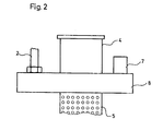
- a pressure relief valve 7 is provided, which sits together with the inlet 4 and the line 2 on a common cover 8 for the container 1.
Landscapes
- Engineering & Computer Science (AREA)
- Chemical & Material Sciences (AREA)
- General Engineering & Computer Science (AREA)
- Materials Engineering (AREA)
- Organic Chemistry (AREA)
- Mechanical Engineering (AREA)
- Sealing Material Composition (AREA)
- Application Of Or Painting With Fluid Materials (AREA)
- Adhesives Or Adhesive Processes (AREA)
Abstract
Description
- Die Erfindung betrifft ein Mittel zum Innenabdichten von Rohrleitungen, insbesondere von Hausgasleitungen.
- Bei älteren Rohrleitungen können Undichtigkeiten auftreten. Dies gilt insbesondere für Hausgasleitungen, die früher von Stadtgas durchströmt wurden und heute mit Erdgas beaufschlagt sind. Stadtgas war feucht, Erdgas ist trocken. Daher neigen die Hanfdichtungen in den Muffen und Anschlüssen zum Austrocknen. Aber auch auf andere Weise können Undichtigkeiten entstehen, beispielsweise durch Vibrationen, sonstige mechanische Beanspruchungen, Korrossion und dergleichen.
- Stellt sich bei einer Überprüfung heraus, daß eine Rohrleitung bzw. ein Rohrleitungsnetz Leckmengen aufweist, die ein vorgegebenes Maß überschreiten, so wird eine grundlegende Reparatur erforderlich. Liegen die Leckmengen hingegen in dem Bereich zwischen dieser Grenze und der unbeschränkten Gebrauchstauglichkeit, so kommt eine Sanierung der Rohrleitung durch Innenabdichtung in Frage.
- Ein bekanntes Mittel der eingangs genannten Art muß mit einem Zeitabstand von ca. 4 Wochen zweimal angewendet werden, um eine tatsächlich wirksame Innenabdichtung zu erzielen. Dementsprechend groß ist der Arbeits- und Materialaufwand. Es handelt sich bei diesem Mittel um eine wässerige Dispersion, deren Feststoffe sich ablagern und anschließend austrocknen. Hierbei entstehen nach dem ersten Arbeitsgang Risse, die durch den zweiten Arbeitsgang geschlossen werden müssen.
- Der Erfindung liegt dementsprechend die Aufgabe zugrunde, eine Mög- lichkeit dafür zu schaffen, eine wirksame Innenabdichtung bereits durch eine einmalige Behandlung zu erzielen.
- Zur Lösung dieser Aufgabe ist das Mittel nach der Erfindung dadurch gekennzeichnet, daß es ein Lösungsmittel, ein Bindemittel und ein Pigment enthält.
- Dieses Mittel besitzt ein hohes Penetrationsvermögen und dringt daher sehr gut in die Undichtigkeiten ein, selbst wenn diese beispielsweise tief in den Gewindegängen von Muffen und dergleichen liegen. Beim Verdunsten des Lösungsmittels bildet das Mittel einen geschlossenen, gasdichten Film, der ein gewisses Maß an Elastizität besitzt. Er haftet gut, und zwar selbst beim Auftreten von Vibrationen. Dabei ist der Film alterungsbeständig, so daß er seine obengenannten Eigenschaften praktisch unbegrenzt beibehält. Übermäßige Schrumpfungen treten ebenfalls nicht auf.
- Andererseits lassen sich auch nach dem Aushärten des Mittels Rohrverbindungsstellen mit handelsüblichen Werkzeugen wieder lösen, und zwar ohne daß es zu Gewindebeschädigungen kommt.
- Das Mittel ist resistent gegen Kondensate, vor allem gegen Isooktan.
- Zu erwähnen ist noch, daß sich das Mittel nicht aggressiv gegen Rohre und Dichtungen verhält. Es ist sogar korrosionsschützend und außerdem physiologisch völlig unbedenklich.
- Vorzugsweise enhält das Mittel 30 - 75 Gew. %, insbesondere 40 - 60 Gew. % Lösungsmittel, 25 - 55 Gew. %, insbesondere 35 - 45 Gew. % Bindemittel und 3 - 15 Gew. %, insbesondere 5 - 10 Gew. % Pigment.
- In der Praxis besonders bewährt hat sich eine Zusammensetzung, bei der das Mittel 58 Gew. % Lösungsmittel, 35 Gew. % Bindemittel und 7 Gew. % Pigment enthält.
- Die obigen Prozentangaben beziehen sich auf den Arbeitszustand.
- Erfindungsgemäß kann das Lösungsmittel ein technischer Alkohol sein. Dies gewährleistet eine besonders gute Verarbeitbarkeit.
- Ferner schlägt die Erfindung vor, daß das Bindemittel Polyvinylbutyral und Epoxydharz-Weichmacher ist. Hierdurch werden insbesondere die Filmbildung, die Elastizität und die Verklebungseigenschaften gefördert, wobei der alterungsbeständige Weichmacher für eine gute Dauerelastizität und eine störungsfreie Trennbarkeit der Muffe auch nach langer Zeit sorgt.
- Es wurde gefunden, daß Polyvinylbutyral und Weichmacher vorzugsweise im Mengenverhältnis 2:1 stehen.
- Erfindungsgemäß kann das Pigment Kalcium-Magnesium-Silikat sein. Dies fördert die Haftung des Films an Metallflächen sowie den Korrosionsschutz des Mittels. Das Pigment besitzt Plättchenstruktur.
- Die Erfindung richtet sich ferner auf ein bevorzugtes Verfahren zum Herstellen des erfindungsgemäßen Mittels, welches dadurch gekennzeichnet ist, daß das Bindemittel unter Rühren heiß im Lösungsmittel gelöst, diese Lösung sodann abgekühlt und anschließend das Pigment eindispergiert wird. Man erzielt dabei ohne weiteres den gewünschten hohen Feststoffanteil an Bindemittel. Das Eindispergieren des Pigments erfolgt am besten in einem Mischer.
- Vorzugsweise schließt sich an das Eindispergieren des Pigments ein Vermahlen an. Hierzu eignen sich beispielsweise hochtourige Perlmühlen. Das Pigment wird sehr feinkörnig und neigt nicht zum Entmischen.
- Als ganz besonders günstig hat es sich herausgestellt, daß erst das Polyvinylbu vral und anschließend der Epoxydharz-Weichermacher in das heiße Lösungsmittel eingerührt wird.
- Die Erfindung betrifft außerdem ein Verfahren zum Innenabdichten von Rohrleitungen, insbesondere von Hausgasleitungen, welches dadurch gekennzeichnet ist, daß das erfindungsgemäße Mittel von unten in die abzudichtende Rohrleitung eingefüllt, dort einige Zeit unter Druck gesetzt (vorzugsweise ca. 30 Min. unter ca. 6 bar) und anschließend unten abgezogen wird, woraufhin man von oben einen Körper aus elastisch kompressiblem Material durch die Leitung hindurchbläst.
- Dadurch wird in zuverlässiger Weise zum einen die Filmbildung erzielt und zum anderen das überschüssige Mittel anschließend ausgetragen. Zum Antrieb des elastisch kompressiblen Körpers dient insbesondere Stickstoff.
- Vorzugsweise wird die Rohrleitung nach dem Austritt des elastisch kompressiblen Körpers von unten abgesaugt. Dies fördert den Austritt des Lösungsmittels und damit die Verfestigung des Films. Auch verhindert man, sofern die Rohrleitung alsbald wieder in Betrieb genommen wird, daß das Lösungsmittel in das transportierte Medium gelangt. Zur Vermeidung von Geruchsbelästigungen führt man den Auslaß des Sauggebläses ins Freie.
- Vorteilhafterweise wird als elastisch kompressibler Körper ein Kunststoffschwamm verwendet. Dieses Material ist billig und steht in beliebigen Größen zur Verfügung. Auch arbeitet es absolut zuverlässig, insbesondere weil es sich auch erheblichen Durchmesseränderungen und Umlenkungen der Rohrleitung ohne weiteres anpaßt.
- Eine bevorzugte Vorrichtung zum Durchführen des erfindungsgemäßen Abdichtverfahrens ist gekennzeichnet durch einen das Mittel aufnehmenden, mit einem Druckgas beaufschlagbaren Behälter, der einen Auslaß zum Füllen der Rohrleitung sowie einen Einlaß größeren Querschnitts zum Entleeren der Rohrleitung aufweist, wobei unterhalb des Einlasses ein Sieb zum Auffangen des elastisch kompressiblen Körpers angeordnet ist.
- Ein und derselbe Behälter dient also zum Füllen und später zum Entleeren der Rohrleitung. Seine Druckbeaufschlagung erfolgt vorzugsweise mit Stickstoff. Durch den vergrößerten Querschnitt des Einlasses wird dafür gesorgt, daß der Kunststoffschwamm ohne weiteres aus der Rohrleitung austreten kann. Das Sieb hindert dann den Kunststoffschwamm am Herabfallen in den Behälter.
- Die erfindungsgemäße Vorrichtung kann ferner dadurch gekennzeichnet sein, daß der Einlaß größeren Querschnitts zusammen mit einem Überdruckventil und einer Druckgas-Leitung an einem gemeinsamen Deckel angeordnet ist. Das Überdruckventil, das beispielsweise bei Einsatz von Stickstoff vorgeschrieben sein kann, wird somit bei jeder Befüllung des Behälters zugänglich und kann demnach leicht gewartet werden. Dadurch wird der Gefahr eines Verklebens durch das im Be:.alter befindliche Mittel begegnet.
- Die erfindungsgemäße Vorrichtung wird im folgenden anhand von bevorzugten Ausführungsbeispielen im Zusammenhang mit der beiliegenden Zeichnung näher erläutert. Die Zeichnung zeigt in:
- Fig. 1 eine schematische Seitenansicht der Vorrichtung;
- Fig. 2 einen für die Vorrichtung geeigneten Deckel.
- Wie dargestellt, ist ein Behälter 1 vorgesehen, der das erfindungsgemäße Mittel enthält. Der Behälter 1 kann über eine Leitung 2 mit Druckgas, insbesondere mit Stickstoff, beaufschlagt werden.
- Ein Auslaß 3 dient dazu, die abzudichtende Rohrleitung von unten mit dem erfindungsgemäßen Mittel zu füllen. Ist der Füllvorgang beendet, so wird das Mittel in der Rohrleitung für 30 Minuten unter einem Druck von 6 bar gehalten.
- Anschließend wird der Druck aufgehoben, und man schließt anstelle des Auslesses 3 einen Einlaß 4 an die Rohrleitung an. 7urch diesen Einlaß fließt das überschüssige Mittel in den Behälter 1 zurück. Um dabei Geruchsbelästigungen zu vermeiden, ist der Behälter mit einer Entlüftung 6 versehen, die ins Freie führt.
- Zur Entfernung der Reste des Mittels wird von oben ein elastisch kompressibler Kunststoffschwamm durch die Rohrleitung hindurchgeblasen. Als Antrieb dient ebenfalls vorzugsweise Stickstoff. Wenn der Kunststoffschwamm die Rohrleitung verläßt, gelangt er durch den Einlaß 4 in den Behälter 1 und wird dort unterhalb des Einlasses von einem Sieb 5 aufgefangen.
- Es schließt sich sodann das Absaugen der Rohrleitung an.
- Gemäß Fig. 2 ist ein Überdruckventil 7 vorgesehen, das zusammen mit dem Einlaß 4 und der Leitung 2 an einem gemeinsamen Deckel 8 für den Behälter 1 sitzt.
- Will man frisches Mittel in den Behälter 1 einfüllen, so geschieht dies durch den Einlaß 4 oder nach Abnahme des Deckels 8.
Claims (17)
Priority Applications (1)
| Application Number | Priority Date | Filing Date | Title |
|---|---|---|---|
| AT83103012T ATE23557T1 (de) | 1982-03-30 | 1983-03-26 | Mittel, verfahren und vorrichtung zum innenabdichten von rohrleitungen. |
Applications Claiming Priority (2)
| Application Number | Priority Date | Filing Date | Title |
|---|---|---|---|
| DE19823211623 DE3211623A1 (de) | 1982-03-30 | 1982-03-30 | Mittel, verfahren und vorrichtung zum innenabdichten von rohrleitungen |
| DE3211623 | 1982-03-30 |
Publications (2)
| Publication Number | Publication Date |
|---|---|
| EP0090384A1 true EP0090384A1 (de) | 1983-10-05 |
| EP0090384B1 EP0090384B1 (de) | 1986-11-12 |
Family
ID=6159658
Family Applications (1)
| Application Number | Title | Priority Date | Filing Date |
|---|---|---|---|
| EP83103012A Expired EP0090384B1 (de) | 1982-03-30 | 1983-03-26 | Mittel, Verfahren und Vorrichtung zum Innenabdichten von Rohrleitungen |
Country Status (3)
| Country | Link |
|---|---|
| EP (1) | EP0090384B1 (de) |
| AT (1) | ATE23557T1 (de) |
| DE (2) | DE3211623A1 (de) |
Cited By (2)
| Publication number | Priority date | Publication date | Assignee | Title |
|---|---|---|---|---|
| EP0326867A3 (en) * | 1988-02-05 | 1990-11-07 | Karl Muller | Method for cleaning and coating pipe systems for water transport |
| US5064486A (en) * | 1987-12-17 | 1991-11-12 | Shell Internationale Research Maatschappij B.V. | Colloidal polymer dispersion for internal sealing of pipes and process for the application thereof |
Citations (3)
| Publication number | Priority date | Publication date | Assignee | Title |
|---|---|---|---|---|
| CH63698A (de) * | 1912-12-14 | 1914-02-16 | Rohr Verdichtungs Ges Mit Besc | Verfahren und Vorrichtung zum Abdichten von Gasleitungen |
| DE2361293B1 (de) * | 1973-12-08 | 1975-03-06 | Basf Farben + Fasern Ag, 2000 Hamburg | Verfahren zur Herstellung von niedrigviskosen Dispersionen transparenter Eisenoxidpigmente in Alkydharzlösungen |
| DD128209A1 (de) * | 1976-11-11 | 1977-11-02 | Manfred Braeuer | Verfahren zum innenabdichten von schadhaften gasinstallationsleitungen |
Family Cites Families (6)
| Publication number | Priority date | Publication date | Assignee | Title |
|---|---|---|---|---|
| BE634750A (de) * | ||||
| US3108012A (en) * | 1960-07-20 | 1963-10-22 | Pipelife Corp | Method of conditioning transmission lines in situ |
| US3144049A (en) * | 1962-06-28 | 1964-08-11 | Standard Oil Co | Method for sealing leaks and leak sealant |
| US3137318A (en) * | 1963-04-08 | 1964-06-16 | Dow Corning | Process for sealing pipelines |
| US3472285A (en) * | 1967-03-24 | 1969-10-14 | Standard Oil Co | Injection leak sealing apparatus and method |
| DE2740940B2 (de) * | 1977-09-10 | 1980-11-27 | Lechler Chemie Gmbh, 7000 Stuttgart | Phenolfreie Mittel zum Wiederabdichten von Stemmuffen in Gasrohrleitungen |
-
1982
- 1982-03-30 DE DE19823211623 patent/DE3211623A1/de not_active Withdrawn
-
1983
- 1983-03-26 AT AT83103012T patent/ATE23557T1/de not_active IP Right Cessation
- 1983-03-26 DE DE8383103012T patent/DE3367610D1/de not_active Expired
- 1983-03-26 EP EP83103012A patent/EP0090384B1/de not_active Expired
Patent Citations (3)
| Publication number | Priority date | Publication date | Assignee | Title |
|---|---|---|---|---|
| CH63698A (de) * | 1912-12-14 | 1914-02-16 | Rohr Verdichtungs Ges Mit Besc | Verfahren und Vorrichtung zum Abdichten von Gasleitungen |
| DE2361293B1 (de) * | 1973-12-08 | 1975-03-06 | Basf Farben + Fasern Ag, 2000 Hamburg | Verfahren zur Herstellung von niedrigviskosen Dispersionen transparenter Eisenoxidpigmente in Alkydharzlösungen |
| DD128209A1 (de) * | 1976-11-11 | 1977-11-02 | Manfred Braeuer | Verfahren zum innenabdichten von schadhaften gasinstallationsleitungen |
Non-Patent Citations (1)
| Title |
|---|
| ULLMANNS ENCYKLOPADIE DER TECHNISCHEN CHEMIE, 4. Auflage, Band 15, 1978 VERLAG CHEMIE, Weinheim-New York Seite 611 * |
Cited By (2)
| Publication number | Priority date | Publication date | Assignee | Title |
|---|---|---|---|---|
| US5064486A (en) * | 1987-12-17 | 1991-11-12 | Shell Internationale Research Maatschappij B.V. | Colloidal polymer dispersion for internal sealing of pipes and process for the application thereof |
| EP0326867A3 (en) * | 1988-02-05 | 1990-11-07 | Karl Muller | Method for cleaning and coating pipe systems for water transport |
Also Published As
| Publication number | Publication date |
|---|---|
| ATE23557T1 (de) | 1986-11-15 |
| EP0090384B1 (de) | 1986-11-12 |
| DE3211623A1 (de) | 1983-10-06 |
| DE3367610D1 (en) | 1987-01-02 |
Similar Documents
| Publication | Publication Date | Title |
|---|---|---|
| DE2355644C3 (de) | Trommelfell-Auslaß aus Kunststoff | |
| DE1650105C3 (de) | Dichtungswerkstoff | |
| DE69106635T2 (de) | Zusatzstoffe und Verfahren zur Kontrolle von Flüssigkeitsverlust von Zementschlamm. | |
| CH662070A5 (en) | Process and device for flushing and cleaning a pipeline | |
| EP0603775B1 (de) | Verfahren zum dichtschliessenden Verbinden eines Kanalrohrs mit einem Anschlussrohr und verspannbares Anschlussrohr hierfür | |
| DE2712870A1 (de) | Dichtungsmittel fuer koksofentueren oder dergleichen | |
| DE3138229A1 (de) | Verfahren zum abdichten und beschichten der innenseiten von rohrleitungen sowie dichtungsmittel zur anwendung fuer das verfahren | |
| EP0090384A1 (de) | Mittel, Verfahren und Vorrichtung zum Innenabdichten von Rohrleitungen | |
| DE60030482T2 (de) | Bodenverbesserungsmittel enthaltend bodenhärter und bodenverbesserer, dessen verwendung sowie eine methode zur bodenverbesserung | |
| DE9411878U1 (de) | Vorrichtung und Anordnung zum Trocknen der Rohrleitungen des Gasleitungssystems eines Hauses | |
| EP0423613A1 (de) | Früh regenfeste Fugendichtungsmassen | |
| DE2126081A1 (de) | Verfahren zum Verkleben von Druckrohren aus Polyvinylchlorid | |
| DE2434606A1 (de) | Filtrierungsverfahren | |
| DE3239429A1 (de) | Verfahren und vorrichtung zum betreiben eines hochdruckstrahlers | |
| DE2718144A1 (de) | Reparatur beschichteter werkstuecke mittels plomben | |
| DE2934023A1 (de) | Nasssandstrahl-verfahren und einrichtung zum durchfuehren des verfahrens | |
| DE1534902C3 (de) | Verfahren zum Abdichten und Füllen von Rissen, Fehlerstellen und dgl. in Bauteilen bzw. Bauwerken sowie Vorrichtung zur Durchführung des Verfahrens | |
| DE3104360A1 (de) | Vorrichtung und verfahren fuer die mauerwerksdurchfuehrung einer versorgungsleitung | |
| DE1932091A1 (de) | Verfahren zum Abdichten von gasfuehrenden undichten Rohrleitungssystemen | |
| DE3531022A1 (de) | Schwebstoffilter | |
| AT408848B (de) | Verfahren zum behandeln von bau- oder dekorationselementen aus stein, kunststein oder holz | |
| DE1494871B2 (de) | Verfahren zum herstellen modifizierter asbestfasern | |
| DE102020109736B4 (de) | Verwendung einer dauerplastisch verformbaren 1-komponentigen Dichtmasse zur Notfallabdichtung eines Lecks in einem Behälter | |
| DE491057C (de) | Vorrichtung zum Reinigen von Bierleitungen | |
| DE618325C (de) | Vorrichtung und Verfahren zum Reinigen von Betonfoerderrohrleitungen |
Legal Events
| Date | Code | Title | Description |
|---|---|---|---|
| PUAI | Public reference made under article 153(3) epc to a published international application that has entered the european phase |
Free format text: ORIGINAL CODE: 0009012 |
|
| AK | Designated contracting states |
Designated state(s): AT BE CH DE FR GB LI LU NL |
|
| RBV | Designated contracting states (corrected) |
Designated state(s): AT BE CH DE FR GB LI LU NL |
|
| 17P | Request for examination filed |
Effective date: 19840330 |
|
| GRAA | (expected) grant |
Free format text: ORIGINAL CODE: 0009210 |
|
| AK | Designated contracting states |
Kind code of ref document: B1 Designated state(s): AT BE CH DE FR GB LI LU NL |
|
| REF | Corresponds to: |
Ref document number: 23557 Country of ref document: AT Date of ref document: 19861115 Kind code of ref document: T |
|
| REF | Corresponds to: |
Ref document number: 3367610 Country of ref document: DE Date of ref document: 19870102 |
|
| ET | Fr: translation filed | ||
| PLBE | No opposition filed within time limit |
Free format text: ORIGINAL CODE: 0009261 |
|
| STAA | Information on the status of an ep patent application or granted ep patent |
Free format text: STATUS: NO OPPOSITION FILED WITHIN TIME LIMIT |
|
| 26N | No opposition filed | ||
| PGFP | Annual fee paid to national office [announced via postgrant information from national office to epo] |
Ref country code: GB Payment date: 19940215 Year of fee payment: 12 |
|
| EPTA | Lu: last paid annual fee | ||
| PG25 | Lapsed in a contracting state [announced via postgrant information from national office to epo] |
Ref country code: GB Effective date: 19950326 |
|
| GBPC | Gb: european patent ceased through non-payment of renewal fee |
Effective date: 19950326 |
|
| PGFP | Annual fee paid to national office [announced via postgrant information from national office to epo] |
Ref country code: CH Payment date: 19990726 Year of fee payment: 17 |
|
| PGFP | Annual fee paid to national office [announced via postgrant information from national office to epo] |
Ref country code: NL Payment date: 19990727 Year of fee payment: 17 |
|
| PGFP | Annual fee paid to national office [announced via postgrant information from national office to epo] |
Ref country code: FR Payment date: 19990728 Year of fee payment: 17 Ref country code: AT Payment date: 19990728 Year of fee payment: 17 |
|
| PGFP | Annual fee paid to national office [announced via postgrant information from national office to epo] |
Ref country code: LU Payment date: 19990729 Year of fee payment: 17 |
|
| PGFP | Annual fee paid to national office [announced via postgrant information from national office to epo] |
Ref country code: BE Payment date: 19990809 Year of fee payment: 17 |
|
| PG25 | Lapsed in a contracting state [announced via postgrant information from national office to epo] |
Ref country code: LU Free format text: LAPSE BECAUSE OF NON-PAYMENT OF DUE FEES Effective date: 20000326 Ref country code: AT Free format text: LAPSE BECAUSE OF NON-PAYMENT OF DUE FEES Effective date: 20000326 |
|
| PG25 | Lapsed in a contracting state [announced via postgrant information from national office to epo] |
Ref country code: LI Free format text: LAPSE BECAUSE OF NON-PAYMENT OF DUE FEES Effective date: 20000331 Ref country code: CH Free format text: LAPSE BECAUSE OF NON-PAYMENT OF DUE FEES Effective date: 20000331 Ref country code: BE Free format text: LAPSE BECAUSE OF NON-PAYMENT OF DUE FEES Effective date: 20000331 |
|
| BERE | Be: lapsed |
Owner name: DIGA - DIE GASHEIZUNG G.M.B.H. Effective date: 20000331 |
|
| PG25 | Lapsed in a contracting state [announced via postgrant information from national office to epo] |
Ref country code: NL Free format text: LAPSE BECAUSE OF NON-PAYMENT OF DUE FEES Effective date: 20001001 |
|
| REG | Reference to a national code |
Ref country code: CH Ref legal event code: PL |
|
| PG25 | Lapsed in a contracting state [announced via postgrant information from national office to epo] |
Ref country code: FR Free format text: LAPSE BECAUSE OF NON-PAYMENT OF DUE FEES Effective date: 20001130 |
|
| NLV4 | Nl: lapsed or anulled due to non-payment of the annual fee |
Effective date: 20001001 |
|
| REG | Reference to a national code |
Ref country code: FR Ref legal event code: ST |
|
| PGFP | Annual fee paid to national office [announced via postgrant information from national office to epo] |
Ref country code: DE Payment date: 20020309 Year of fee payment: 20 |