EP0090473A1 - Bâtiment, panneaux de paroi et profils pour les mêmes - Google Patents
Bâtiment, panneaux de paroi et profils pour les mêmes Download PDFInfo
- Publication number
- EP0090473A1 EP0090473A1 EP83200437A EP83200437A EP0090473A1 EP 0090473 A1 EP0090473 A1 EP 0090473A1 EP 83200437 A EP83200437 A EP 83200437A EP 83200437 A EP83200437 A EP 83200437A EP 0090473 A1 EP0090473 A1 EP 0090473A1
- Authority
- EP
- European Patent Office
- Prior art keywords
- building
- plates
- walls
- posts
- sections
- Prior art date
- Legal status (The legal status is an assumption and is not a legal conclusion. Google has not performed a legal analysis and makes no representation as to the accuracy of the status listed.)
- Granted
Links
- 230000002093 peripheral effect Effects 0.000 claims abstract description 28
- 239000010960 cold rolled steel Substances 0.000 claims abstract description 12
- 239000000463 material Substances 0.000 claims description 10
- 229910052602 gypsum Inorganic materials 0.000 claims description 3
- 239000010440 gypsum Substances 0.000 claims description 3
- 239000011490 mineral wool Substances 0.000 claims description 3
- 239000004568 cement Substances 0.000 claims description 2
- 239000011120 plywood Substances 0.000 claims description 2
- 238000000926 separation method Methods 0.000 claims 2
- 238000000034 method Methods 0.000 description 13
- 238000010276 construction Methods 0.000 description 11
- 239000002023 wood Substances 0.000 description 10
- 238000009413 insulation Methods 0.000 description 8
- 210000003414 extremity Anatomy 0.000 description 5
- 239000011248 coating agent Substances 0.000 description 3
- 238000000576 coating method Methods 0.000 description 3
- 230000000694 effects Effects 0.000 description 3
- 239000011449 brick Substances 0.000 description 2
- 238000004519 manufacturing process Methods 0.000 description 2
- 238000007665 sagging Methods 0.000 description 2
- 230000009897 systematic effect Effects 0.000 description 2
- 210000001364 upper extremity Anatomy 0.000 description 2
- 229920005830 Polyurethane Foam Polymers 0.000 description 1
- XAGFODPZIPBFFR-UHFFFAOYSA-N aluminium Chemical compound [Al] XAGFODPZIPBFFR-UHFFFAOYSA-N 0.000 description 1
- 229910052782 aluminium Inorganic materials 0.000 description 1
- 239000004411 aluminium Substances 0.000 description 1
- 230000005540 biological transmission Effects 0.000 description 1
- 230000015572 biosynthetic process Effects 0.000 description 1
- 238000005097 cold rolling Methods 0.000 description 1
- 239000006260 foam Substances 0.000 description 1
- 239000011888 foil Substances 0.000 description 1
- -1 for example Substances 0.000 description 1
- 230000002401 inhibitory effect Effects 0.000 description 1
- 239000011810 insulating material Substances 0.000 description 1
- 239000011505 plaster Substances 0.000 description 1
- 239000011496 polyurethane foam Substances 0.000 description 1
- 230000002250 progressing effect Effects 0.000 description 1
- 239000004575 stone Substances 0.000 description 1
- 229920003002 synthetic resin Polymers 0.000 description 1
- 239000000057 synthetic resin Substances 0.000 description 1
Images


Classifications
-
- E—FIXED CONSTRUCTIONS
- E04—BUILDING
- E04B—GENERAL BUILDING CONSTRUCTIONS; WALLS, e.g. PARTITIONS; ROOFS; FLOORS; CEILINGS; INSULATION OR OTHER PROTECTION OF BUILDINGS
- E04B1/00—Constructions in general; Structures which are not restricted either to walls, e.g. partitions, or floors or ceilings or roofs
- E04B1/02—Structures consisting primarily of load-supporting, block-shaped, or slab-shaped elements
- E04B1/08—Structures consisting primarily of load-supporting, block-shaped, or slab-shaped elements the elements consisting of metal
Definitions
- the invention relates to a building comprising walls constructed from frameworks of horizontal and vertical posts provided on at least one side with plates imparting resistance to deformation.and span elements disposed on the walls such als floor beams or rafters.
- Such a building may be a building constructed in accordance with the wood skeleton building method.
- the wood skeleton building method all supporting and non-supporting elements above the foundation, that is to say, the walls, the floors and the roof are made from wood with the exception of any coating and insulating materials.
- the skeleton of the walls comprises horizontal and vertical posts of standarized dimensions, which are joined by simple nail joints.
- the resistance to deformation of the building is obtained by the plates arranged on the frameworks and, of course, by the bond of the walls with one another.
- a conventional mode of construction consists in that the storey floor is disposed on the erected walls of the first floor, then the storey walls are disposed on the storey floor and on these storey walls are again arranged the storey floors for the higher storey or the rafters.
- the wood skeleton building method has several important advantages.
- One particularly important advantage is that this method usually does not impose any limitation on the designer and that any desired construction can be carried into effect by this method.
- the building height is usually limited to three or four storeys.
- a building constructed by the wood skeleton building method is relatively cheap and a high insulating value can be obtained in a simple manner.
- a further advantage is that such a building has materially lower weight than a building of bricks or concrete. Owing to these advantages buildings are frequently erected in accordance with the wood skeleton building method in the U.S.A. and in Canada. In other countries too this method is progressing, since the highly increased building costs result in a growing interest in building methods by which high-grade buildings can be made, but which involve reasonable costs.
- the object of the present invention is to provide a building constructed by a system which combines the most important advantages of the wood building method with the actual industrial possibilities.
- each wall of separate sections having at least one circumferential framework of cold-rolled steel plate profiles, adjacent sections being mounted in contact with one another by the vertical peripheral posts and the span elements being disposed above the vertical peripheral posts.
- Cold-rolled steel plate profiles have low weight in accordance with the advantages of the wood skeleton building. Whereas in the wood skeleton building the wall absorbs vertical loads throughout the length, the greater rigidity of cold-rolled steel plate profiles permit of erecting the walls in sections, whose vertical peripheral posts exclusively absorb vertical forces. Consequently inside each section door or window openings can be quite freely made without the need for providing lintels laterally deflecting the vertical load.
- any desired construction can be carried into effect when the sections in inner and outer walls have each a length lying in a range including: a complete module size, half the module size and the full and half module size minus once or twice respectively the thickness of the section. Therefore the industrial manufacture of at least the frameworks for the sections becomes interesting in view of the comparatively small number of different sections. For any building no or only very few specific sections need be made. For example, when the building to be erected has an inclined roof only few sections having an inclined side are required.
- the posts are provided at equal intervals with perforations for passing conduits and fastening means.
- the sections are delivered on the building site provided with outer plates or as the case may be, with a temporary strut so that after the erection of the walls and the floors of the building the conduits can be arranged in place in a very simple manner. Subsequently the inner plates are mounted.
- the horizontal peripheral posts have a U-section profile and the vertical peripheral posts have an open-box profile, the width of the open-box profile corresponding to the inner distance between the limbs of the U-profile.
- the vertical peripheral posts can be fitted by their ends in the horizontal peripheral posts and in this structure the vertical posts may be very thin whilst maintaining sufficient rigidity.
- the horizontal and vertical posts may be advantageously interconnected by a known cold-riveting method which is a very fast method requiring little effort.
- the vertical peripheral posts are provided for this purpose in their side faces with depressions around the perforations for the passage of rivets passed through corresponding perforations in the horizontal peripheral posts.
- the material of the horizontal peripheral posts is slightly drawn inwardly into the depression of the vertical peripheral post concerned.
- the head of the rivet can be drawn inside the plane of the framework so that the plates can be smoothly mounted on the framework.
- the span elements are made from cold-rolled steel plate profiles. As stated above, they are relatively rigid in reasonable sizes so that the distance between two neighbouring span elements may be large. Since the span elements are disposed above the vertical peripheral posts of the sections, these sections may consequently have a large module size.
- the floor comprises girders being formed by two identical, substantially U-shaped profiles mounted web to web, the webs comprising each a profile part re-entrant in the direction towards the associated limbs.
- the re-entrant profile parts thus constitute a long cavity in the mounted state of the two identical profiles matching high rigidity with very low weight.
- the building according to the invention may be provided with any desired outer coating, for example, bricks, natural stone, plaster and so on.
- the outer coating is formed by asbestos-cement boards or a similar material.
- the plates on the inner side of the building are preferably gypsum boards.
- a suitable thickness for the sections is, for example, 10 cms.
- the invention furthermore relates to and provides wall sections for use in a building embodying the invention.
- a wall section comprises at least one peripheral framework of cold-rolled steel plate profiles and a deformation- resisting element such as plates or a strut.
- a strut is used for transport when the plates are mounted only on the building site.
- the invention also relates to and provides the cold-rolled steel plate profiles which are apparently intended for use in a wall section or a building as described above. By means of these profiles the user himself can erect a simple or, if desired, more complicated building without the need for having great professional skill.
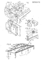
- the building 1 comprises walls, for example, a ground floor wall 2, a storey wall 3, a loft wall 4 and front walls 5 and 6 at the first floor and the ground floor respectively.
- These walls 2 to 6 are formed by vertical posts 8 and horizontal posts 9.
- each wall is constructed from separate sections 7 having a circumferential framework 12 of cold-rolled steel plate profiles so that adjacent sections 7 are mounted to one another by the vertical peripheral posts 8.
- the sections are provided on at least one side with plates, for example, an inner plate 10 and/or an outer plate 11.
- the ground floor walls such as 2 and 6 are erected on a foundation 15 consisting of foundation beams 16, which may be arranged on piles, and a system floor 17 of known type arranged between the foundation beams.
- the storey floor comprises girders 19, between which joists 20 are arranged.
- the girders 19 are disposed on the sections 7 of the walls above the vertical peripheral posts thereof. Consequently not any vertical effort is exerted on the upper horizontal peripheral post of each section.
- On the floor beams 19,20 is then arranged a floor slab 21.
- the floor slabs 21 are preferably made from multi-plywood; they also contribute to the deformation resistance of the construction.
- the wall sections 7 for the first-floor walls such as 3 and 5 are erected on the storey floor that is to say on the slabs 21.
- a loft floor 22 is placed on these first-floor walls in the same manner as the first floor 18.
- the loft floor 22 is also provided with floor slabs 23.
- a flat roof 24 which also consists of girders and joists, said roof having a structure corresponding with that of the storey floor 18 and the loft floor 22 and thus also being provided with slabs 26.
- the roof plates 25 for the inclined roof faces are arranged in a manner to be described more fully hereinafter.
- a window 30 in a section without the need for further precautions such as lintels and the like by connecting a window profile 31 with the vertical intermediate posts and by providing the inner and outer plates with a recess.
- a window frame can be mounted as is shown in Fig. 5.
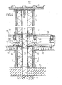
- Fig. 2 shows that in accordance with the invention perforations 32 are provided at equal intervals in the posts of the sections 7.
- the girders 19 also have perforations 32 at equal intervals. These perforations can be effectively made prior to cold-rolling of the profiles.
- the perforations 32 serve to pass conduits through the walls and the floor construction.
- a socket 34 is arranged in the perforation 32.
- Other conduits such as the conduit 35 may be directly passed through the perforation concerned.
- Fig. 2 furthermore shows that the horizontal posts of each section 7 are formed by C-section profiles and the vertical posts 8 by open-box profiles.
- the width of the open-box profile 8 corresponds to the distance between the limbs of the horizontal posts 9 so that the vertical posts can fit in the horizontal posts.
- the posts 8 of two adjacent sections 7 are interconnected, for example, by a cold rivet joint.
- the girder 19 shown disposed on the vertical peripheral posts 8 is formed by two identical, substantially U-shaped profiles mounted web-to-web. The webs each have a profiled part re-entrant in the direction of the associated limbs so that in the composed state a hollow cylinder 28 is formed.
- the girder thus constructed has a very high rigidity and an indifferent behaviour to buckling.
- the webs of the profiles 27 may again be interconnected by a cold rivet joint.
- a number of profile parts 36 on which the joists 20 are mounted On the side face of the girder 19 are arranged a number of profile parts 36 on which the joists 20 are mounted. As is shown, the joists preferably have an open-box profile.
- the profile parts 36 are fastened with the aid of rivets 37 to the girder 19.
- the holes for the rivets as well as the perforations 32 for passing ducts are provided in an operation preceding the profile formation of the material.
- the horizontally extending upper limb of the profile part 36 has a bore through which extends a bolt 39 which is engaged in the screwthread of a clamping piece 38. When mounting the joist 20 the clamping piece 38 is turned for about one quarter stroke with respect to the position shown in Fig.
- the bolt 39 is tightened so that the inwardly folded limbs of the profile of the joist 20 are clamped tight between the clamping piece 38 and the upper limb of the profile part 36. Since the holes for the rivet 37 are previously accurately positioned in the girder 19, the upper face of the joist 20 will lie on the same level as the upper face of the girder 19 without the need for further means.
- the joist 20 At its front end the joist 20 has a recess 40 so that it can engage the girder 19 in the manner shown in Fig. 2.
- the ceiling plates 45 are suspended in known manner by means of hangers 46 to the joists 20. It is thus possible to arrange an insulation blanket of mineral wool on the entire surface of the ceiling and hence right below the girders.
- the inner plates 10,45 are preferably gypsum plates, which are also satisfactorily resistant to fire.
- double plates may be arranged on the inner side rather than the plates on the cavity side. In this way the resistance to collapsing of the walls is appreciably raised.
- Fig. 4 shows that between two opposite storey floors, in the cavity between two separating walls an insulation 49 is arranged. This insulation serves to prevent fire from passing to the adjacent house through said interspace. Above at the wall, where the roof plate 25 is lying on the section concerned there is also provided the insulation 50. Otherwise it is apparent that the storey wall 3 is disposed on the floor slab 21 of the storey floor.
- a window frame 54 is mounted on the boudary of the profile 31.
- the window frame 54 is milled from a material in a manner such that a ridge 60 is formed, which covers the outer plate 11.
- a finishing fillet 55 is provided on the inner side.
- insulation tape of synthetic foam may be arranged between the outer plates 11 and the framework 12 of the section concerned.
- This tape 52 not only reduces transfer of heat but also limits sound transmission.
- the tape is applied to the posts at least near the areas where the plates are fastened. This is shown in detail in Fig. 10.
- a plate 53 is arranged for bridging the interspace caused by the storey floor.
- Fig. 6 shows the construction in the area of the ridge of the roof.
- a girder 19 On the normal section 7 and the triangular section 64 of the loft wall 4 is disposed in known manner a girder 19.
- a plate 26 To the girder 19 and the joist 20 connected with the former is fastened a plate 26.
- a triangular profile 61 is fastened around the plate 26.
- a filling piece 62 On the upright side of the triangular profile 61 is arranged a filling piece 62.
- the roof plate 25, which is formed in this embodiment by two relatively spaced aluminium plates with polyurethane foam sandwiched between, is fastened to the triangular profile 61.
- a covering profile 63 is provided and in known manner several layers of roofing material 65 are arranged on the resultant construction.
- the building shown in the Figures represents only one potential design.
- the construction embodying the invention has the advantage that the freedom of design is hardly limited. Owing to the systematics of the structure a highly economic building method is obtained.
- the sections and the inner and outer walls have each a length lying in a range including a full module size, half a module size and a full and half a module size minus once or twice the thickness of the section.
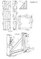
- Sections having lengths in this range are shown in Fig. 8.
- the section 71 shown has a length equal to half a module size 76.
- the section 70 has a length equal to a full module size, that is to say, twice half the module size 76. With regard to commercially available sizes of sheet materials an appropriate module size is 2.50 ms.
- the section 70 has four interspaces between vertical posts 8 so that the interspace between two neighbouring posts is each time 60 cms in this module size.
- the section 73 has a length equal to half the module size 76 minus once the thickness of a section. This size is designated by 77.
- the section 72 has a length equal to a full module size minus the wall thickness.
- section 75 has a length 78 equal to half the module size ,minus twice the wall thickness and the section 74 has a length equal to the full module size minus twice the wall thickness.
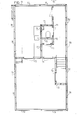
- FIG. 7 shows a sectional plan view of the ground floor of the building 1, in which the various sections are designated by the reference numerals of Fig. 8. It should be noted that the door openings are each arranged inside a section so that the sections extend on both sides of the door openings.
- the sections in order to have the required resistance to deformation, have to be provided during transport with at least one stiffening element, for example, a plate or a strut. It is particularly interesting to provide the sections to be used in the outer walls previously with the outer plates so that the building is closed within a very short time. In those cases in which it is more effective to mount the plates afterwards, which may apply in particular to the inner walls, the sections can be transported and erected whilst being provided with a temporary strut. In Fig. 8 these temporary struts are indicated by broken lines 80.
- Fig. 10 shows further details of the manner in which the frameworks 12 of the sections are mounted.
- the vertical profiles 8 are preferably formed by open-box profiles and the horizontal posts 9 prefereably by U-profiles.
- the vertical posts 8 have around the holes 85 depressions 86.
- a horizontal post 9 is connected with a vertical post 8 by means of a rivet 87, the material of the horizontal post 9 is drawn inwardly into the depression 86 during the riveting operation, preferably a cold riveting operation so that a depression is also formed in the material of the post 9.
- the head of the bolt 87 will lie within the side face of the framework.
- the strut 80 is preferably fastened temporarily with the aid of a plate screw 89. When the framework is set up the strut 80 can be rapidly removed by loosening the screws 89.
- the insulation tape 52 Prior to mounting the plates 11 the insulation tape 52 is applied in the manner described above.
- the plates 11 are preferably fastened also with the aid of plate screws 90. These plate screws may effectively be of the self-fixing type.
- Fig. 10 the wall thicknesses of the profiles are represented on an exaggerated scale. It has been found that for a building 1 as shown in Fig. 1 a thickness of the material of the profiles 8 and 9 of about 1.5 mms is sufficient.
- the building shown in Figs. 11 and 12 (92) also comprises walls composed of the sections 7 described in the foregoing.
- the rafters 93 are formed by open-box profiles 94 and 95.
- the head plate 96 is fastened by means of rivets 97.
- the posts 91 are inserted into the open side of the profiles and fixed in place by rivets.
- girders 98 are arranged across the rafters 93.
- These girders 98 are preferably fastened to the rafters 93 in the manner corresponding to the fastening mode of the joists 20 to the girders 19.
- the girders 98 also have an open-box profile and clamped to the rafters by means of a clamping plate 99 in which a screwthreaded bolt 100 is engaged.
- a roofing plate On the girders 98 is arranged a roofing plate in known manner.
- a building 92 of the kind shown in Figs. 11 and 12 may very effectively serve as a temporary dwelling or as a barn, a shed or the like.
Landscapes
- Engineering & Computer Science (AREA)
- Architecture (AREA)
- Physics & Mathematics (AREA)
- Electromagnetism (AREA)
- Civil Engineering (AREA)
- Structural Engineering (AREA)
- Load-Bearing And Curtain Walls (AREA)
- Finishing Walls (AREA)
- Building Environments (AREA)
Priority Applications (1)
| Application Number | Priority Date | Filing Date | Title |
|---|---|---|---|
| AT83200437T ATE20933T1 (de) | 1982-03-29 | 1983-03-28 | Gebaeude, wandelemente und profile fuer dieselben. |
Applications Claiming Priority (2)
| Application Number | Priority Date | Filing Date | Title |
|---|---|---|---|
| NL8201299 | 1982-03-29 | ||
| NL8201299A NL8201299A (nl) | 1982-03-29 | 1982-03-29 | Gebouw, wandsecties en profielen daarvoor. |
Publications (2)
| Publication Number | Publication Date |
|---|---|
| EP0090473A1 true EP0090473A1 (fr) | 1983-10-05 |
| EP0090473B1 EP0090473B1 (fr) | 1986-07-23 |
Family
ID=19839498
Family Applications (1)
| Application Number | Title | Priority Date | Filing Date |
|---|---|---|---|
| EP83200437A Expired EP0090473B1 (fr) | 1982-03-29 | 1983-03-28 | Bâtiment, panneaux de paroi et profils pour les mêmes |
Country Status (4)
| Country | Link |
|---|---|
| EP (1) | EP0090473B1 (fr) |
| AT (1) | ATE20933T1 (fr) |
| DE (1) | DE3364630D1 (fr) |
| NL (1) | NL8201299A (fr) |
Cited By (7)
| Publication number | Priority date | Publication date | Assignee | Title |
|---|---|---|---|---|
| GB2148975A (en) * | 1983-11-05 | 1985-06-05 | Ash & Lacy Plc | Wall/roof assemblies |
| FR2624158A1 (fr) * | 1987-12-07 | 1989-06-09 | Sercca | Dispositif de facade legere de batiment |
| DE19606857A1 (de) * | 1996-02-23 | 1997-08-28 | Chiemgauer Holzhaus Siemer & Z | Vorgefertigtes Wandelement für ein Gebäude |
| DE19620296C1 (de) * | 1996-05-21 | 1997-11-27 | Adolf Imhoff | Verbundsystem für Bauzwecke mit selbsttragenden Tafelelementen |
| DE19854401A1 (de) * | 1998-11-25 | 2000-06-15 | Compaktbau Flohr Raumsysteme G | Bauteilsatz zur Erstellung vorzugsweise mehrgeschossiger gebäudetechnisch vollausgestatteter Baukörper |
| DE10012483A1 (de) * | 2000-03-15 | 2001-09-27 | Christoph Bornebusch | Gebäude aus fabrikmäßig vorgefertigten Bauelementen und Verfahren zur Errichtung desselben |
| CN117468610A (zh) * | 2023-12-27 | 2024-01-30 | 中国建筑设计研究院有限公司 | 一种防屈曲箱板式围壁墙板结构及其设计方法 |
Citations (5)
| Publication number | Priority date | Publication date | Assignee | Title |
|---|---|---|---|---|
| US2073781A (en) * | 1932-07-06 | 1937-03-16 | Salvator S Calafati Jr | Building construction |
| US2356309A (en) * | 1941-05-09 | 1944-08-22 | Gustav W Garbe | Construction unit |
| FR1528620A (fr) * | 1966-09-09 | 1968-06-14 | Panneaux porteurs préfabriqués et construction utilisant de tels panneaux | |
| US4161089A (en) * | 1977-12-14 | 1979-07-17 | Omansky Martin B | Modular building structure system |
| FR2486565A1 (fr) * | 1980-07-09 | 1982-01-15 | Lacoste Maurice | Ossature industrialisee destinee a la construction et au contreventement de parois |
-
1982
- 1982-03-29 NL NL8201299A patent/NL8201299A/nl not_active Application Discontinuation
-
1983
- 1983-03-28 DE DE8383200437T patent/DE3364630D1/de not_active Expired
- 1983-03-28 EP EP83200437A patent/EP0090473B1/fr not_active Expired
- 1983-03-28 AT AT83200437T patent/ATE20933T1/de not_active IP Right Cessation
Patent Citations (5)
| Publication number | Priority date | Publication date | Assignee | Title |
|---|---|---|---|---|
| US2073781A (en) * | 1932-07-06 | 1937-03-16 | Salvator S Calafati Jr | Building construction |
| US2356309A (en) * | 1941-05-09 | 1944-08-22 | Gustav W Garbe | Construction unit |
| FR1528620A (fr) * | 1966-09-09 | 1968-06-14 | Panneaux porteurs préfabriqués et construction utilisant de tels panneaux | |
| US4161089A (en) * | 1977-12-14 | 1979-07-17 | Omansky Martin B | Modular building structure system |
| FR2486565A1 (fr) * | 1980-07-09 | 1982-01-15 | Lacoste Maurice | Ossature industrialisee destinee a la construction et au contreventement de parois |
Non-Patent Citations (1)
| Title |
|---|
| BOUWWERELD, vol. 67, no. 15, 9th April 1971, pages 44-45, Deetinchem, NL. * |
Cited By (10)
| Publication number | Priority date | Publication date | Assignee | Title |
|---|---|---|---|---|
| GB2148975A (en) * | 1983-11-05 | 1985-06-05 | Ash & Lacy Plc | Wall/roof assemblies |
| FR2624158A1 (fr) * | 1987-12-07 | 1989-06-09 | Sercca | Dispositif de facade legere de batiment |
| EP0320359A1 (fr) * | 1987-12-07 | 1989-06-14 | Sercca | Dispositif de façade légère de bâtiment |
| DE19606857A1 (de) * | 1996-02-23 | 1997-08-28 | Chiemgauer Holzhaus Siemer & Z | Vorgefertigtes Wandelement für ein Gebäude |
| DE19606857C2 (de) * | 1996-02-23 | 2001-07-05 | Chiemgauer Holzhaus Siemer & Z | Vorgefertigtes Wandelement für ein Gebäude |
| DE19620296C1 (de) * | 1996-05-21 | 1997-11-27 | Adolf Imhoff | Verbundsystem für Bauzwecke mit selbsttragenden Tafelelementen |
| DE19854401A1 (de) * | 1998-11-25 | 2000-06-15 | Compaktbau Flohr Raumsysteme G | Bauteilsatz zur Erstellung vorzugsweise mehrgeschossiger gebäudetechnisch vollausgestatteter Baukörper |
| DE10012483A1 (de) * | 2000-03-15 | 2001-09-27 | Christoph Bornebusch | Gebäude aus fabrikmäßig vorgefertigten Bauelementen und Verfahren zur Errichtung desselben |
| CN117468610A (zh) * | 2023-12-27 | 2024-01-30 | 中国建筑设计研究院有限公司 | 一种防屈曲箱板式围壁墙板结构及其设计方法 |
| CN117468610B (zh) * | 2023-12-27 | 2024-03-22 | 中国建筑设计研究院有限公司 | 一种防屈曲箱板式围壁墙板结构及其设计方法 |
Also Published As
| Publication number | Publication date |
|---|---|
| NL8201299A (nl) | 1983-10-17 |
| ATE20933T1 (de) | 1986-08-15 |
| EP0090473B1 (fr) | 1986-07-23 |
| DE3364630D1 (en) | 1986-08-28 |
Similar Documents
| Publication | Publication Date | Title |
|---|---|---|
| US5740643A (en) | Fireproof building | |
| US4068434A (en) | Composite wall panel assembly and method of production | |
| US3363371A (en) | Erection of prefabricated houses | |
| US4644708A (en) | Prefabricated modular building element and a building comprising such elements | |
| US3256652A (en) | Building of assembled box-shaped elements | |
| US4478018A (en) | Thermal break exterior insulated wall framing system | |
| US4641468A (en) | Panel structure and building structure made therefrom | |
| US4441286A (en) | Prefabricated cube construction system for housing and civic development | |
| US7421828B2 (en) | Integral forming technology, a method of constructing steel reinforced concrete structures | |
| US2191804A (en) | Building construction unit | |
| US4759160A (en) | Prefabricated concrete buildings with monolithic roof, wall, and floor members | |
| US4894964A (en) | Building structure and method | |
| US4909001A (en) | System of housing and building construction by means of prefabricated components | |
| CA1124482A (fr) | Panneaux de construction, et batiments faits desdits panneaux | |
| PL194067B1 (pl) | Sposób budowy budynków | |
| US4310992A (en) | Structural panel | |
| US5996296A (en) | Prefabricated structural panel | |
| EP0090473B1 (fr) | Bâtiment, panneaux de paroi et profils pour les mêmes | |
| US4274242A (en) | Building systems | |
| US5491942A (en) | Multi-story building construction employing prefabricated elements | |
| HU183339B (en) | Variable building construction | |
| EP0051592B1 (fr) | Batiment | |
| US2073781A (en) | Building construction | |
| EP1080278B1 (fr) | Batiment, notamment batiment a consommation d'energie reduite | |
| US1955818A (en) | Metallic frame for buildings |
Legal Events
| Date | Code | Title | Description |
|---|---|---|---|
| PUAI | Public reference made under article 153(3) epc to a published international application that has entered the european phase |
Free format text: ORIGINAL CODE: 0009012 |
|
| AK | Designated contracting states |
Designated state(s): AT BE CH DE FR GB IT LI LU NL SE |
|
| 17P | Request for examination filed |
Effective date: 19840322 |
|
| GRAA | (expected) grant |
Free format text: ORIGINAL CODE: 0009210 |
|
| AK | Designated contracting states |
Kind code of ref document: B1 Designated state(s): AT BE CH DE FR GB IT LI LU NL SE |
|
| PG25 | Lapsed in a contracting state [announced via postgrant information from national office to epo] |
Ref country code: LI Effective date: 19860723 Ref country code: IT Free format text: LAPSE BECAUSE OF FAILURE TO SUBMIT A TRANSLATION OF THE DESCRIPTION OR TO PAY THE FEE WITHIN THE PRESCRIBED TIME-LIMIT;WARNING: LAPSES OF ITALIAN PATENTS WITH EFFECTIVE DATE BEFORE 2007 MAY HAVE OCCURRED AT ANY TIME BEFORE 2007. THE CORRECT EFFECTIVE DATE MAY BE DIFFERENT FROM THE ONE RECORDED. Effective date: 19860723 Ref country code: FR Free format text: THE PATENT HAS BEEN ANNULLED BY A DECISION OF A NATIONAL AUTHORITY Effective date: 19860723 Ref country code: DE Effective date: 19860723 Ref country code: CH Effective date: 19860723 Ref country code: BE Effective date: 19860723 Ref country code: AT Effective date: 19860723 |
|
| REF | Corresponds to: |
Ref document number: 20933 Country of ref document: AT Date of ref document: 19860815 Kind code of ref document: T |
|
| PG25 | Lapsed in a contracting state [announced via postgrant information from national office to epo] |
Ref country code: SE Effective date: 19860731 |
|
| REF | Corresponds to: |
Ref document number: 3364630 Country of ref document: DE Date of ref document: 19860828 |
|
| REG | Reference to a national code |
Ref country code: CH Ref legal event code: PL |
|
| EN | Fr: translation not filed | ||
| PG25 | Lapsed in a contracting state [announced via postgrant information from national office to epo] |
Ref country code: LU Free format text: LAPSE BECAUSE OF NON-PAYMENT OF DUE FEES Effective date: 19870331 |
|
| PLBE | No opposition filed within time limit |
Free format text: ORIGINAL CODE: 0009261 |
|
| STAA | Information on the status of an ep patent application or granted ep patent |
Free format text: STATUS: NO OPPOSITION FILED WITHIN TIME LIMIT |
|
| 26N | No opposition filed | ||
| GBPC | Gb: european patent ceased through non-payment of renewal fee | ||
| PG25 | Lapsed in a contracting state [announced via postgrant information from national office to epo] |
Ref country code: GB Effective date: 19881122 |
|
| PGFP | Annual fee paid to national office [announced via postgrant information from national office to epo] |
Ref country code: NL Payment date: 19900331 Year of fee payment: 8 |
|
| PG25 | Lapsed in a contracting state [announced via postgrant information from national office to epo] |
Ref country code: NL Effective date: 19911001 |
|
| NLV4 | Nl: lapsed or anulled due to non-payment of the annual fee |