EP0090594B1 - Szintillationskamera - Google Patents
Szintillationskamera Download PDFInfo
- Publication number
- EP0090594B1 EP0090594B1 EP83301626A EP83301626A EP0090594B1 EP 0090594 B1 EP0090594 B1 EP 0090594B1 EP 83301626 A EP83301626 A EP 83301626A EP 83301626 A EP83301626 A EP 83301626A EP 0090594 B1 EP0090594 B1 EP 0090594B1
- Authority
- EP
- European Patent Office
- Prior art keywords
- collimator
- plates
- scintillation camera
- shield plates
- gamma rays
- Prior art date
- Legal status (The legal status is an assumption and is not a legal conclusion. Google has not performed a legal analysis and makes no representation as to the accuracy of the status listed.)
- Expired
Links
- 238000009826 distribution Methods 0.000 claims description 25
- 230000009466 transformation Effects 0.000 claims description 12
- 230000005855 radiation Effects 0.000 claims description 8
- 238000004364 calculation method Methods 0.000 claims description 7
- 239000000463 material Substances 0.000 claims description 6
- 125000006850 spacer group Chemical group 0.000 claims description 4
- 230000000063 preceeding effect Effects 0.000 claims 1
- 239000011159 matrix material Substances 0.000 description 9
- XEEYBQQBJWHFJM-UHFFFAOYSA-N Iron Chemical compound [Fe] XEEYBQQBJWHFJM-UHFFFAOYSA-N 0.000 description 8
- 230000000694 effects Effects 0.000 description 8
- 230000002285 radioactive effect Effects 0.000 description 6
- 238000000034 method Methods 0.000 description 5
- 238000010276 construction Methods 0.000 description 4
- 238000010586 diagram Methods 0.000 description 4
- 230000005251 gamma ray Effects 0.000 description 4
- 229910052742 iron Inorganic materials 0.000 description 4
- 230000000007 visual effect Effects 0.000 description 4
- 229920006267 polyester film Polymers 0.000 description 3
- 238000001179 sorption measurement Methods 0.000 description 3
- 230000010365 information processing Effects 0.000 description 2
- 230000035945 sensitivity Effects 0.000 description 2
- 239000007787 solid Substances 0.000 description 2
- RYGMFSIKBFXOCR-UHFFFAOYSA-N Copper Chemical compound [Cu] RYGMFSIKBFXOCR-UHFFFAOYSA-N 0.000 description 1
- 238000010521 absorption reaction Methods 0.000 description 1
- 239000000853 adhesive Substances 0.000 description 1
- 238000002591 computed tomography Methods 0.000 description 1
- 229910052802 copper Inorganic materials 0.000 description 1
- 239000010949 copper Substances 0.000 description 1
- 230000008878 coupling Effects 0.000 description 1
- 238000010168 coupling process Methods 0.000 description 1
- 238000005859 coupling reaction Methods 0.000 description 1
- 238000004519 manufacturing process Methods 0.000 description 1
- 230000003287 optical effect Effects 0.000 description 1
- 239000013307 optical fiber Substances 0.000 description 1
- 210000000056 organ Anatomy 0.000 description 1
- 229920000728 polyester Polymers 0.000 description 1
Images




Classifications
-
- G—PHYSICS
- G01—MEASURING; TESTING
- G01T—MEASUREMENT OF NUCLEAR OR X-RADIATION
- G01T1/00—Measuring X-radiation, gamma radiation, corpuscular radiation, or cosmic radiation
- G01T1/16—Measuring radiation intensity
- G01T1/161—Applications in the field of nuclear medicine, e.g. in vivo counting
- G01T1/164—Scintigraphy
- G01T1/1641—Static instruments for imaging the distribution of radioactivity in one or two dimensions using one or several scintillating elements; Radio-isotope cameras
- G01T1/1644—Static instruments for imaging the distribution of radioactivity in one or two dimensions using one or several scintillating elements; Radio-isotope cameras using an array of optically separate scintillation elements permitting direct location of scintillations
-
- G—PHYSICS
- G01—MEASURING; TESTING
- G01T—MEASUREMENT OF NUCLEAR OR X-RADIATION
- G01T1/00—Measuring X-radiation, gamma radiation, corpuscular radiation, or cosmic radiation
- G01T1/16—Measuring radiation intensity
- G01T1/161—Applications in the field of nuclear medicine, e.g. in vivo counting
- G01T1/164—Scintigraphy
- G01T1/1641—Static instruments for imaging the distribution of radioactivity in one or two dimensions using one or several scintillating elements; Radio-isotope cameras
- G01T1/1642—Static instruments for imaging the distribution of radioactivity in one or two dimensions using one or several scintillating elements; Radio-isotope cameras using a scintillation crystal and position sensing photodetector arrays, e.g. ANGER cameras
-
- A—HUMAN NECESSITIES
- A61—MEDICAL OR VETERINARY SCIENCE; HYGIENE
- A61B—DIAGNOSIS; SURGERY; IDENTIFICATION
- A61B6/00—Apparatus or devices for radiation diagnosis; Apparatus or devices for radiation diagnosis combined with radiation therapy equipment
- A61B6/02—Arrangements for diagnosis sequentially in different planes; Stereoscopic radiation diagnosis
- A61B6/03—Computed tomography [CT]
- A61B6/037—Emission tomography
-
- A—HUMAN NECESSITIES
- A61—MEDICAL OR VETERINARY SCIENCE; HYGIENE
- A61B—DIAGNOSIS; SURGERY; IDENTIFICATION
- A61B6/00—Apparatus or devices for radiation diagnosis; Apparatus or devices for radiation diagnosis combined with radiation therapy equipment
- A61B6/42—Arrangements for detecting radiation specially adapted for radiation diagnosis
- A61B6/4208—Arrangements for detecting radiation specially adapted for radiation diagnosis characterised by using a particular type of detector
- A61B6/4258—Arrangements for detecting radiation specially adapted for radiation diagnosis characterised by using a particular type of detector for detecting non x-ray radiation, e.g. gamma radiation
Definitions
- the present invention relates to a scintillation camera for obtaining a picture of distribution of a radioactive isotope (RI).
- RI radioactive isotope
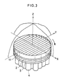
- One of two representative types of the Anger scintillation camera is equipped with a lattice type collimator as shown in Figs. 1 and 2, while the other is equipped with a parallel plate collimator which is rotatable in construction as shown in Figs. 3 to 5.
- radioactive rays are collimated by the lattice type collimator 1 so that only those which are incoming perpendicularly to the surface of a flat type scintillator 2 (i.e., which are incoming in the direction of the Z axis) may be fed to the scintillator 2.
- a plurality of photomultipliers 4 arranged on the back of the scintillator 2 emit outputs which correspond to the scintillations of light.
- the numeral 3 designates light guides for optical coupling.
- These outputs are fed to a position calculation circuit 5, in which the positions of scintillations (i.e., the positions on which the gamma rays are incident) are calculated from these outputs so that position signals X and Y may be developed.
- a display unit 6 dots are displayed in the positions determined by the position signals X and Y. These dots gather in the picture and indicate a distribution of RI as it is viewed in the direction of the Z axis.
- the specific organ 8 of a subject 7, in which RI is allowed to collect can be diagnosed.
- the rotating-collimator type scintillation camera can be constructed from an ordinary scintillation camera.
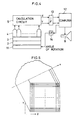
- the lattice type collimator 1 (Fig. 1) is replaced by a parallel plate collimator 11 (Fig. 3) which is rotatably held, adapted to be rotated by a suitable mechanism, and connected to a computer 12 through interface circuits 13 and 14 as shown in Fig. 4.
- the angle of piecemeal rotation is specified by the computer 12. Every time the collimator 11 has rotated by the specified angle, signals X and Y are taken into the computer 12 and stored in the memory circuit thereof.
- the signals X and Y developed by the position calculation circuit 5 of the scintillation camera are listed as the picture elements of a two-dimensional matrix (Fig.
- the two-dimensional matrix In order to improve the accuracy of a reconstructed image, the two-dimensional matrix must be sufficiently fine-meshed and the collimator 11 must be adapted to be rotated by as small angular distances as possible so that data on one-dimensional distribution may be obtained in as great numbers as possible. Let it be supposed that, in order to meet this requirement, data on one-dimensional distribution are going to be obtained from a two-dimensional matrix having a mesh size of 512x512 every time the collimator 11 rotates by 0.5 degree in the course of 180-degree rotation.
- the first object of the present invention is to provide a scintillation camera which is based on a different principle from that of the conventional scintillation cameras and into which a computerized technique of image information processing is introduced so as to free the images from distortion and allow the camera to be highly sensitive and to have a high practical spatial resolution.
- Anger-type cameras are revealed as being provided with collimators having a first plurality of parallel shield plates, spaced apart by a second plurality of corrugated or zig-zag shield plates; both formed of a similar material such as lead.
- FR-A-2336112 there is also disclosed the step of arranging that the gamma ray adsorption is differential as between the first and second plurality of shield plates by means of a suitable spatial arrangement.
- this last step of arranging for differential gamma ray adsorption is achieved by selecting for the second plurality of shield plates a material which has a lower gamma ray adsorption.
- a scintillation camera comprising a rotatable collimator formed with a first plurality of parallel lateral shield plates, a scintillation radiation detector, processing means responsive to signals produced by the radiation detector, and means for reconstitution of an image.
- the present invention is characterised in that the collimator is provided with a second plurality of shield plates each extending lengthwise to intersect the first plurality of plates, each of said second plurality of plates being regularly spaced to define a series of approximately equal areas in the lateral direction, and in that the processing means integrates the number of incident gamma rays in the lengthwise direction on each small angular rotation of the collimator and collects data on the distribution of the number of incident rays in a direction perpendicular to the lateral shield plates.
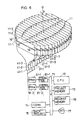
- a plurality of long and slender scintillators 21-1, 21-2, 21-3,... are arranged so as to allow their lateral edges to abut each other and so as together to form a flat disk-shape array.
- Light emitted by the scintillators 21-1, 21-2, 21-3,..., which is position independent in the lengthwise direction of the scintillator array is fed to photoelectric converters such as photomultipliers (PMT) 41-1, 41-2,41-3,... through light guides 31-1, 31-2, 31-3,..., respectively, which comprise means such as optical fibers.
- PMT photomultipliers
- a parallel plate collimator 11 for restricting gamma rays which are incoming perpendicularly to the plane of the array, to each scintillator is provided on the front side of the scintillator array 21-1, 21-2, 21-3, ...
- the collimator 11 consists of a first set of shielding plates 11-1, 11-2, 11-3,... arranged in parallel with each other and a second set of shielding plates 16 disposed at both ends and in the middle portion of the first set of shielding plates so as to intersect them.
- Said plates 16 are adapted to restrict, to some extent, gamma rays which are incoming parallel to the lateral edges of each scintillator.
- the scintillators 21-1, 21-2, 21-3,..., together with the collimator 11, are adapted to be revolved about the 0 axis either by 180° or by 360°.
- a data P in the form of a histogram as shown in Fig. 7 is obtained by arranging these discrete values in the same order as that in which the scinillators 21-1, 21-2, 21-3,... are arranged.
- the data P r after passage through an interface 71, is written in a memory 73 under the control of a central processing unit (CPU) 72.
- CPU central processing unit
- convolution is carried out by a convolver 74 in the first place and then back projection is carried out by a back projector 75 so that the image, which represents a distribution of RI, may be written in an image memory 76, reconstructed therein as a one which consists, e.g., of a 256x256 matrix, and displayed by a display unit such as a CRT 77.
- the collimators have only to restrict gamma rays which are incoming perpendicularly to the plane of the scintillator array.
- the embodiment shown in Fig. 6 is devoid of the second set of shielding plates 16 and consequently the gamma rays which are incoming in the lengthwise direction of the scintillators are not restricted at all, the distribution of counting rates obtained in the lengthwise direction of each scintillator will show itself in the form of a prolate curve as shown in Fig. 8 with a broken curve.
- the above-mentioned prolate curve may be regarded as indicating that a scintillator which is devoid of the second set of shielding plates 16 has an especially wide range of low-sensitivity end portions and is apt to produce an artifically narrow effective visual field.
- the second set of shielding plates 16 are not provided at both ends of the first set of shielding plates 11-1, 11-2, 11-3,..., gamma rays incident on the scintillators from the exterior of the visual field will constitute a major cause of inaccuracy.
- the second set of shielding plates 16 are disposed at either side, intermediate and in the middle portion, of the first set of shielding plates 11-1, 11-2, 11-3,... as shown in Fig. 6 so that gamma rays which are incoming in the lengthwise direction of the scintillators may be restricted. Consequently the distribution of counting rates obtained in the lengthwise direction of each scintillator shows itself in the form of a comparatively oblate curve as shown in Fig. 8 with a solid curve, which indicates a narrow range of low sensitivity end portions and a wide area of effective visual field.
- the shielding plates 16 provided on the circumference of the scintillator assembly serve to substantially prevent the incidence of gamma rays from the exterior of the visual field.
- the plurality of long and slender scintillators 21-1, 21-2, 21-3,... are used for integrating the number of incident gamma rays in the lengthwise direction of the first set of shielding plates 11-1, 11-2, 11-3,... of the parallel plate collimator 11, and for collecting data on the distribution of integrated counting rates in the direction perpendicular to the plane of the scintillator array
- the long and slender scintillators are not the only form which may be taken by a radiation detector.
- the radiation detector may take any other forms so long as they allow the above-mentioned distribution to be found.
- the scintillators and collimator in the above-described embodiment of the present invention are shaped like a disk as a whole, it goes without saying that they may be rectangularly shaped.
- the second set of shielding plates 16' are preferably disposed in such a manner that their lower edges abut against the upper edges of the first set of shielding plates 11-1, 11-2, 11-3,... of the collimator 11 so as to form solid crossings as shown in Fig. 9.
- the collimators used with the scintillation camera of the invention need not be arcuate, but it may of course be parallel plates arranged in such a manner that the first and the second parallel plates form a right angled lattice.
- the parallel plate collimator need not necessarily make a right angle with the upper surface of each scintillator, but may be inclined (e.g., at 60°) as shown by the numeral 11' in Fig. 10. In this case, data can be obtained in the course of 360- degree rotation and a longitudinal tomogram can be obtained in any depth.
- This embodiment which bears some resemblance to the construction of a conventional scintillation camera shown in Fig. 4, differs therefrom in that the collimator 11 shown in Fig. 6 or 9 is used and that a coordinate transformation circuit 15 is interposed between the position calculation circuit 5 and the interface circuit 13.
- the coordinate transformation circuit 15 By the coordinate transformation circuit 15, the XY coordinates of the position calculation circuit 5 are transformed into xy coordinates which represent the position occupied by the XY coordinates of the collimator 11 when it has rotated by a predetermined angle.
- Coordinate transformation is carried out as shown in Fig. 12 in accordance with the following formulae in the coordinate transformation circuit 15 upon receipt of a signal from the computer 12 which indicates the angle of rotation 8:
- the signal y is neglected (i.e., either fixed in the coordinate transformation circuit or prevented from being fed out therefrom), and only the signal x is fed to a memory location in the computer 12 which is allotted for each point of incidence of a radioactive ray.
- the signals x are fed to the memory locations in this manner and are enumerated in the direction of the x axis, which is at an angular distance of 8 from the X axis, so that data on one-dimensional distribution in that direction may be obtained. This procedure is repeated at various angular distances from the X axis in the cou rse of 180° or 360° deg ree rotation so that al the data required for image reconstruction may be collected.
- the above-described construction serves to simplify the computer operation, because the provision of a coordinate transformation circuit 15 allows automatic addition to be carried out in each memory location. Because coordinate transformation takes place in real-time, the time interval from the instant the operation is started until the instant the data on one-dimensional distribution is obtained can be reduced and consequently an image can be quickly delivered. Above all, it is noteworthy that a drastically smaller number of memory locations suffice for the collection of data. For example, let it be supposed that data are going to be collected with the one dimensional density of picture elements and the number of angular positions of the collimator being equal to those presupposed for the above-mentioned two-dimensional matrix. Then the number of memory locations required for the collection of data amounts only to 512x360 in all, which are 1/512 as many as the number of memory locations required for the conventional two-dimensional matrix.
- a plurality of plates 11 a are arranged so as to be equally spaced perpendicularly to the X axis.
- a corrugated member 11 b is inserted as a spacer into each space between adjacent plates 11a a and unified therewith by means of an adhesive agent or the like.
- the plates 11 a are made of a material such as lead, so that they absorb gamma rays.
- the members 11b b are made, e.g., of an iron or copper sheet, which is inferior to the plates 11a in their gamma ray absorption properties, or of a polyester sheet, which hardly absorbs gamma rays at all, and has excellent penetrability thereto.
- each corrugated member 11 shown in Figs. 13 and 14 forms triangular openings in combination with adjacent plates 11a,thetriangte is not exhaustive of the forms which may be taken by these openings. They may be square as shown in Fig. 15 so long as their axes run parallel with the Z axis.
- FIG. 16 helps explain how to evaluate such effects.
- a lead plate 11 c provided with a pinhole 11 d is disposed under the collimator of the type shown in Figs. 13 and 14 (or in Fig. 15).
- a miniature radiation detector 11 D is disposed substantially under the pinhole 11d.
- a radioactive source S which is disposed over the collimator, is moved in the directions of the X and Y axes so that the counting rates per unit time may be measured. Distribution curves as shown in Fig. 17 are obtained when the counting rates found in a direction are plotted on an ordinate against the traveling distance of the radioactive source on an abscissa.
- Curves a and b show the distributions of counting rates measured in the direction of the Y axis with polyester films and iron sheets respectively used as the members 11 b.
- the distribution of counting rates measured in the direction of the X axis, which is shown by the curve c, is unrelated to the material of which the members 11 b are made.
- the implication of the curves a and c is that polyester films hardly have an effect in the direction of the Y axis although they have the effect in the direction of the X axis.
- the implication of the curve b is that the effect of the iron sheets in the direction of the Y axis stands midway between the effects of the iron sheets and the polyester films in the direction of the X axis.
- the collimator is allowed to have any degree of anisotropy. The degree depends on whether a material having a pronounced or slight property of absorbing gamma rays is used for the corrugated members 11 b.
- the present invention uses a collimator of simplified construction for ease of manufacture, which is derived from the facts that the corrugated members can be easily manufactured with high accuracy and that they serve both as spacers and as an anisotropic field stop.
- Gamma rays which are incoming in the direction of the Z axis do not undergo attenuation, because they are not absorbed by the corrugated members.
Landscapes
- Physics & Mathematics (AREA)
- Health & Medical Sciences (AREA)
- Engineering & Computer Science (AREA)
- Biomedical Technology (AREA)
- General Health & Medical Sciences (AREA)
- Medical Informatics (AREA)
- Nuclear Medicine, Radiotherapy & Molecular Imaging (AREA)
- Optics & Photonics (AREA)
- Life Sciences & Earth Sciences (AREA)
- General Physics & Mathematics (AREA)
- High Energy & Nuclear Physics (AREA)
- Molecular Biology (AREA)
- Spectroscopy & Molecular Physics (AREA)
- Nuclear Medicine (AREA)
Claims (6)
Applications Claiming Priority (2)
| Application Number | Priority Date | Filing Date | Title |
|---|---|---|---|
| JP57052870A JPS58169078A (ja) | 1982-03-31 | 1982-03-31 | シンチレ−シヨンカメラ |
| JP52870/82 | 1982-03-31 |
Publications (2)
| Publication Number | Publication Date |
|---|---|
| EP0090594A1 EP0090594A1 (de) | 1983-10-05 |
| EP0090594B1 true EP0090594B1 (de) | 1987-03-11 |
Family
ID=12926906
Family Applications (1)
| Application Number | Title | Priority Date | Filing Date |
|---|---|---|---|
| EP83301626A Expired EP0090594B1 (de) | 1982-03-31 | 1983-03-23 | Szintillationskamera |
Country Status (4)
| Country | Link |
|---|---|
| US (1) | US4563583A (de) |
| EP (1) | EP0090594B1 (de) |
| JP (1) | JPS58169078A (de) |
| DE (1) | DE3370193D1 (de) |
Families Citing this family (13)
| Publication number | Priority date | Publication date | Assignee | Title |
|---|---|---|---|---|
| US4654795A (en) * | 1984-03-20 | 1987-03-31 | Elscint Ltd. | Image processing systems and methods |
| FR2567276B1 (fr) * | 1984-07-06 | 1988-02-19 | Labo Electronique Physique | Perfectionnement apporte a une camera pour la detection de rayonnements x et g, camera dont le bloc scintillateur possede une fenetre d'entree formee d'une structure-support mecaniquement rigide et tres faiblement absorbante auxdits rayonnements |
| FR2673728B1 (fr) * | 1991-03-08 | 1997-01-31 | Assist Publique | Systeme de gamma camera a haute sensibilite |
| JPH04297899A (ja) * | 1991-03-27 | 1992-10-21 | Toshiba Corp | コリメータ製造方法及び該製造方法で得るコリメータ |
| JP3311043B2 (ja) * | 1992-10-23 | 2002-08-05 | 株式会社東芝 | ガンマカメラ |
| US5528659A (en) * | 1994-04-25 | 1996-06-18 | Gray*Star, Inc. | Radiation flux polarizer or distributor |
| US5712483A (en) * | 1996-06-28 | 1998-01-27 | The Regents Of The University Of California | X-ray grid-detector apparatus |
| FR2757954B1 (fr) * | 1996-12-30 | 1999-01-22 | Commissariat Energie Atomique | Tete de detection et collimateur pour gamma-camera |
| US6130430A (en) * | 1997-02-21 | 2000-10-10 | Picker International, Inc. | Septal artifact cancellation in positron emission tomography |
| US6603123B1 (en) * | 2000-11-08 | 2003-08-05 | Koninklijke Philips Electronics, N.V. | Correction for depth-dependent sensitivity in rotating slat-collimated gamma camera |
| US7323688B2 (en) * | 2004-06-29 | 2008-01-29 | Siemens Medical Solutions Usa, Inc. | Nuclear imaging system using rotating scintillation bar detectors with slat collimation and method for imaging using the same |
| US20120087462A1 (en) * | 2010-10-12 | 2012-04-12 | Abdelaziz Ikhlef | Hybrid collimator for x-rays and method of making same |
| JP2014241543A (ja) * | 2013-06-12 | 2014-12-25 | 株式会社東芝 | 光検出装置およびct装置 |
Family Cites Families (6)
| Publication number | Priority date | Publication date | Assignee | Title |
|---|---|---|---|---|
| US3937969A (en) * | 1973-05-07 | 1976-02-10 | G. D. Searle & Co. | Gamma ray camera system with corrugated collimators |
| US4060730A (en) * | 1973-09-07 | 1977-11-29 | Elscint, Ltd. | Scintillation camera for establishing the coordinates of a radiation stimuli produced by a radiation field |
| US4057726A (en) * | 1975-12-22 | 1977-11-08 | G. D. Searle & Co. | Collimator trans-axial tomographic scintillation camera |
| US4047037A (en) * | 1976-02-09 | 1977-09-06 | The Ohio State University | Gamma ray camera for nuclear medicine |
| NL7608031A (nl) * | 1976-07-20 | 1978-01-24 | Optische Ind De Oude Delft Nv | Collimator. |
| US4281382A (en) * | 1977-12-21 | 1981-07-28 | Medtronic, Inc. | Radiation signal processing system |
-
1982
- 1982-03-31 JP JP57052870A patent/JPS58169078A/ja active Pending
-
1983
- 1983-03-23 DE DE8383301626T patent/DE3370193D1/de not_active Expired
- 1983-03-23 US US06/478,011 patent/US4563583A/en not_active Expired - Lifetime
- 1983-03-23 EP EP83301626A patent/EP0090594B1/de not_active Expired
Also Published As
| Publication number | Publication date |
|---|---|
| US4563583A (en) | 1986-01-07 |
| DE3370193D1 (en) | 1987-04-16 |
| JPS58169078A (ja) | 1983-10-05 |
| EP0090594A1 (de) | 1983-10-05 |
Similar Documents
| Publication | Publication Date | Title |
|---|---|---|
| US6762413B2 (en) | Correction for depth-dependent sensitivity in rotating slat-collimated gamma camera | |
| EP0090594B1 (de) | Szintillationskamera | |
| US4095107A (en) | Transaxial radionuclide emission camera apparatus and method | |
| US3778614A (en) | Method and apparatus for measuring x- or {65 -radiation absorption or transmission at plural angles and analyzing the data | |
| US4057727A (en) | Positron imaging system with improved count rate and tomographic capability | |
| US5506408A (en) | Gamma camera | |
| JP7520431B2 (ja) | 検知装置及びspect結像システム | |
| US5753917A (en) | Dual crystal scintillation camera | |
| WO1990016001A2 (en) | Enlarged detector rotating ring array pet scanner | |
| WO1997014059A1 (en) | Resolution enhancement for dual head gamma camera | |
| WO1996039641A9 (en) | Dual crystal scintillation camera | |
| US7323688B2 (en) | Nuclear imaging system using rotating scintillation bar detectors with slat collimation and method for imaging using the same | |
| WO2018044606A1 (en) | Systems and methods for controlling optical coupling between scintillator crystals | |
| DE69622759T2 (de) | Streuungs-filter für emissionstomographie | |
| JPH1172564A (ja) | ガンマカメラシステム | |
| WO2001036996A1 (fr) | Dispositif d'imagerie de positrons | |
| EP0846275A1 (de) | Abbildungsvorrichtung | |
| US20040200965A1 (en) | Radiographic inspection apparatus and radiographic inspection method | |
| US4639600A (en) | Radiation detector | |
| US20050029461A1 (en) | Gamma camera using rotating scintillation bar detector and method for tomographic imaging using the same | |
| Bartzakos et al. | A PET detector with depth-of-interaction determination | |
| Hua | Compton imaging system development and performance assessment | |
| US3792274A (en) | Scintillation camera with improved resolution | |
| JPS62203078A (ja) | 放射線位置検出器 | |
| JPS58169076A (ja) | シンチレ−シヨンカメラ |
Legal Events
| Date | Code | Title | Description |
|---|---|---|---|
| PUAI | Public reference made under article 153(3) epc to a published international application that has entered the european phase |
Free format text: ORIGINAL CODE: 0009012 |
|
| AK | Designated contracting states |
Designated state(s): DE FR GB NL |
|
| 17P | Request for examination filed |
Effective date: 19840305 |
|
| GRAA | (expected) grant |
Free format text: ORIGINAL CODE: 0009210 |
|
| AK | Designated contracting states |
Kind code of ref document: B1 Designated state(s): DE FR GB NL |
|
| REF | Corresponds to: |
Ref document number: 3370193 Country of ref document: DE Date of ref document: 19870416 |
|
| ET | Fr: translation filed | ||
| PLBE | No opposition filed within time limit |
Free format text: ORIGINAL CODE: 0009261 |
|
| STAA | Information on the status of an ep patent application or granted ep patent |
Free format text: STATUS: NO OPPOSITION FILED WITHIN TIME LIMIT |
|
| 26N | No opposition filed | ||
| PGFP | Annual fee paid to national office [announced via postgrant information from national office to epo] |
Ref country code: GB Payment date: 19910313 Year of fee payment: 9 |
|
| PGFP | Annual fee paid to national office [announced via postgrant information from national office to epo] |
Ref country code: FR Payment date: 19910320 Year of fee payment: 9 |
|
| PGFP | Annual fee paid to national office [announced via postgrant information from national office to epo] |
Ref country code: NL Payment date: 19910331 Year of fee payment: 9 |
|
| PGFP | Annual fee paid to national office [announced via postgrant information from national office to epo] |
Ref country code: DE Payment date: 19910430 Year of fee payment: 9 |
|
| PG25 | Lapsed in a contracting state [announced via postgrant information from national office to epo] |
Ref country code: GB Effective date: 19920323 |
|
| PG25 | Lapsed in a contracting state [announced via postgrant information from national office to epo] |
Ref country code: NL Effective date: 19921001 |
|
| NLV4 | Nl: lapsed or anulled due to non-payment of the annual fee | ||
| GBPC | Gb: european patent ceased through non-payment of renewal fee | ||
| PG25 | Lapsed in a contracting state [announced via postgrant information from national office to epo] |
Ref country code: FR Effective date: 19921130 |
|
| PG25 | Lapsed in a contracting state [announced via postgrant information from national office to epo] |
Ref country code: DE Effective date: 19921201 |
|
| REG | Reference to a national code |
Ref country code: FR Ref legal event code: ST |