EP0090647A1 - Verfahren zur Detergensherstellung - Google Patents
Verfahren zur Detergensherstellung Download PDFInfo
- Publication number
- EP0090647A1 EP0090647A1 EP83301765A EP83301765A EP0090647A1 EP 0090647 A1 EP0090647 A1 EP 0090647A1 EP 83301765 A EP83301765 A EP 83301765A EP 83301765 A EP83301765 A EP 83301765A EP 0090647 A1 EP0090647 A1 EP 0090647A1
- Authority
- EP
- European Patent Office
- Prior art keywords
- cavities
- rotor
- soap
- stator
- process according
- Prior art date
- Legal status (The legal status is an assumption and is not a legal conclusion. Google has not performed a legal analysis and makes no representation as to the accuracy of the status listed.)
- Granted
Links
- 238000012545 processing Methods 0.000 title claims description 12
- 239000003599 detergent Substances 0.000 title claims description 4
- 239000000344 soap Substances 0.000 claims abstract description 16
- 239000002304 perfume Substances 0.000 claims abstract description 5
- 239000000203 mixture Substances 0.000 claims abstract 4
- 238000009472 formulation Methods 0.000 claims abstract 3
- 239000000463 material Substances 0.000 claims description 32
- 238000000034 method Methods 0.000 claims description 10
- 238000006073 displacement reaction Methods 0.000 claims description 3
- 238000012546 transfer Methods 0.000 description 10
- XMGQYMWWDOXHJM-UHFFFAOYSA-N limonene Chemical compound CC(=C)C1CCC(C)=CC1 XMGQYMWWDOXHJM-UHFFFAOYSA-N 0.000 description 4
- PEDCQBHIVMGVHV-UHFFFAOYSA-N Glycerine Chemical compound OCC(O)CO PEDCQBHIVMGVHV-UHFFFAOYSA-N 0.000 description 3
- -1 alcohol sulphates Chemical class 0.000 description 3
- WRMNZCZEMHIOCP-UHFFFAOYSA-N 2-phenylethanol Chemical compound OCCC1=CC=CC=C1 WRMNZCZEMHIOCP-UHFFFAOYSA-N 0.000 description 2
- 235000013162 Cocos nucifera Nutrition 0.000 description 2
- 244000060011 Cocos nucifera Species 0.000 description 2
- 238000001816 cooling Methods 0.000 description 2
- 238000010438 heat treatment Methods 0.000 description 2
- 238000010348 incorporation Methods 0.000 description 2
- 229940087305 limonene Drugs 0.000 description 2
- 235000001510 limonene Nutrition 0.000 description 2
- 235000012149 noodles Nutrition 0.000 description 2
- 230000000717 retained effect Effects 0.000 description 2
- 239000003760 tallow Substances 0.000 description 2
- 150000001298 alcohols Chemical class 0.000 description 1
- 150000004996 alkyl benzenes Chemical class 0.000 description 1
- 238000004458 analytical method Methods 0.000 description 1
- 239000011324 bead Substances 0.000 description 1
- 238000004891 communication Methods 0.000 description 1
- 238000010276 construction Methods 0.000 description 1
- 239000000498 cooling water Substances 0.000 description 1
- 230000000694 effects Effects 0.000 description 1
- 239000012530 fluid Substances 0.000 description 1
- 239000003205 fragrance Substances 0.000 description 1
- 238000004817 gas chromatography Methods 0.000 description 1
- 239000008236 heating water Substances 0.000 description 1
- 239000007788 liquid Substances 0.000 description 1
- 239000002184 metal Substances 0.000 description 1
- JRZJOMJEPLMPRA-UHFFFAOYSA-N olefin Natural products CCCCCCCC=C JRZJOMJEPLMPRA-UHFFFAOYSA-N 0.000 description 1
- 239000002245 particle Substances 0.000 description 1
- 239000002904 solvent Substances 0.000 description 1
Images



Classifications
-
- C—CHEMISTRY; METALLURGY
- C11—ANIMAL OR VEGETABLE OILS, FATS, FATTY SUBSTANCES OR WAXES; FATTY ACIDS THEREFROM; DETERGENTS; CANDLES
- C11D—DETERGENT COMPOSITIONS; USE OF SINGLE SUBSTANCES AS DETERGENTS; SOAP OR SOAP-MAKING; RESIN SOAPS; RECOVERY OF GLYCEROL
- C11D13/00—Making of soap or soap solutions in general; Apparatus therefor
- C11D13/10—Mixing; Kneading
-
- C—CHEMISTRY; METALLURGY
- C11—ANIMAL OR VEGETABLE OILS, FATS, FATTY SUBSTANCES OR WAXES; FATTY ACIDS THEREFROM; DETERGENTS; CANDLES
- C11D—DETERGENT COMPOSITIONS; USE OF SINGLE SUBSTANCES AS DETERGENTS; SOAP OR SOAP-MAKING; RESIN SOAPS; RECOVERY OF GLYCEROL
- C11D13/00—Making of soap or soap solutions in general; Apparatus therefor
- C11D13/08—Colouring, e.g. striated bars or striped bars, or perfuming
Definitions
- This invention relates to the processing of soap feedstocks to introduce volatile components, for example perfumes.
- a cavity transfer mixer provides an efficient route for incorporation because the processing temperatures are maintained, in general, below those usually encountered in soap processing. The processing time is low and the mixing occurs in an enclosed volume. The energy required will normally be lower than that required in conventional processes.
- the present invention uses a device of the cavity transfer mixer class to introduce a volatile component into the soap base.
- These devices comprise two closely spaced mutually displaceable surfaces each having a pattern of cavities which overlap during movement of surfaces so that material moved between the surfaces traces a path through cavities alternately in each surface so that the bulk of the material passes through the shear zone in the material generated by displacement of the surfaces.
- Cavity transfer mixers are normally prepared with a cylindrical geometry and in the preferred devices for this process the cavities are arranged to give constantly available but changing ways path through the device during mutual movement of the two surfaces.
- the devices having a cylindrical geometry will comprise a stator within which is journalled a rotor; the opposing faces of the stator and rotor carry the cavities through which the material passes during its passage through the device.
- the temperature of processing is preferably from about 30°C to about 55°C, more preferably below about 40°C.
- the device may also have a planar geometry in which opposed plane surfaces having patterns of cavities would be moved mutually, for example by rotation of one plane, so that material introduced between the surfaces at the point of rotation would move outwards and travel alternately between cavities on each surface.
- auxilliary equipment As the rotor is turned.
- auxilliary equipment are screw extruders and piston rams.
- the auxiliary equipment is preferably operated separately from the mixer so that the throughput and work performed on it can be separately varied.
- the separate operation may be achieved by arranging the auxiliary equipment to provide material for processing at an angle to the centre line of the shear-producing device. This arrangement allows rotational energy to be supplied to the device producing shear around its centre line. An in-line arrangement is more easily achieved when the external member of the device is the rotor. Separate operation of the device and auxiliary equipment assists in providing control of the processing.
- cavity shapes In general a variety of cavity shapes can be used, for example Metal Box (UK 930 339) disclose longitudinal slots in the two surfaces.
- the stator and rotor may carry slots, for example six to twelve, spaced around their periphery and extending along their whole length.
- one or both surfaces are subjected to thermal control.
- the process allows efficient heating /cooling of the materials to be achieved.
- the detergent feedstock may contain non-soap detergents in amounts which would not interfere with the desired effect.
- these actives are alkane sulphonates, alcohol sulphates, alkyl benzene sulphonates, alkyl sulphates, acyl isethionates, olefin sulphonates and ethoxylated alcohols.
- the processed feedstock was made into bar form using standard stamping machinery.
- Other product forms eg extruded particles (noodles) and beads can be prepared from the feedstock.
- a cavity transfer mixer is shown in Figure 1 in longitudinal section. This comprises a hollow cylindrical stator member 1, a cylindrical rotor member 2 journalled for rotation within the stator with a sliding fit, the facing cylindrical surfaces of the rotor and stator carrying respective pluralities of parallel, circumferentially extending rows of cavities which are disposed with:
- the pattern of cavities carried on the stator 3 and rotor 4 are illustrated on Figure 3.
- the cavities 3 on the stator are shown hatched.
- the overlap between patterns of cavities 3, 4 is also shown in Figure 2.
- a liquid jacket 1A is provided for the application of temperature control by the passage of heating or cooling water.
- a temperature control conduit 2A is provided in the rotor.
- the material passing through the device moves through the cavities alternately on the opposing faces of the stator and rotor.
- the cavities immediately behind those shown in section are indicated by dotted profiles on Figure 1 to allow the repeating pattern to be seen.
- the material flow is divided between pairs of adjacent cavities on the same rotor or stator face because of the overlapping position of the cavity on the opposite stator or rotor face.
- the whole or bulk of the material flow is subjected to considerable working during its passage through the shear zone generated by the mutual displacement of the stator and rotor surfaces.
- the material is entrained for a short period in each cavity during passage and thus one of its velocity components is altered.
- the mixer had a rotor radius of 2.54 cm with 36 hemispherical cavities (radius 0.9 cm) arranged in six rows of six cavities.
- the internal surface of the stator carried seven rows of six cavities to provide cavity overlap at the entry and exit.
- the material to be worked was injected into the device through channel 5, which communicates with the annular space between the rotor and stator, during operation by a screw extruder. The material left the device through nozzle 6.
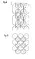
- Figure 4 shows elongate cavities arranged in a square pattern; these cavities have the sectional profile of Figure 2. These cavities are aligned with their longitudinal axis parallel to the longitudinal axis of the device and the direction of movement of material through the device; the latter is indicated by the arrow.
- Figure 5 shows a pattern of cavities having the dimensions and profile of those shown in Figures 1, 2 and 3.
- the cavities of Figure 5 are arranged in a square pattern with each cavity being closely spaced from flow adjacent cavities on the same surface. This pattern does not provide as high a degree of overlap as given by the pattern of Figure 3.
- the latter has each cavity closely spaced to six cavities on the same surface, ie a hexagonal pattern.
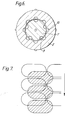
- Figure 6 is a section of a cavity transfer mixer having a rotor 7 rotatably positioned within the hollow stator 8 having an effective length of 10.7 cm and a diameter of 2.54 cm.
- the rotor carried five parallel grooves 9 of semi-circular cross section (diameter 5 mm) equally spaced around the periphery and extending parallel to the longitudinal axis along the length of the rotor.
- the inner cylindrical surface of the stator 8 carried eight grooves 10 of similar dimensions extending along its length and parallel to the longitudinal axis. This embodiment, utilised cavities extending along the length of the stator and rotor without interruption. Temperature control jacket and conduit were present.
- Figure 7 shows a pattern of cavities wherein the cavities on the rotor, shown hatched, and stator have a larger dimension normal to the material flow; the latter is indicated by an arrow.
- the cavities are thus elongate.
- This embodiment provides a lower pressure drop over its length compared with devices of similar geometry but not having cavities positioned with a longer dimension normal, i.e. perpendicular to the material flow. To obtain a reduction in pressure drop at least one of the surfaces must carry elongate cavities having their longer dimension normal to the material flow.
- the cavity transfer mixer of Figure 8 had the external cylinder 11 journalled for rotation about central shaft 12. Temperature control jacket 13 and conduit were present but the latter is now shown because the cavities on the central shaft are shown in plan view while the rotor is sectioned.
- the central stator (diameter 52 mm) had three rows 14 of three cavities with partial, i.e. half cavities at the entry and exit points. On the rotor there were four rows 15 of three cavities.
- the cavities on the stator and rotor were elongate with a total arc dimension of 5.1 cm normal to the material flow with hemispherical section ends of 1.2 cm radius joined by a semicircular sectioned panel of the same radius.
- the cavities were arranged in the pattern of Figure 7, i.e. with their long dimension normal to material flow.
- the rotor was driven by a chain drive to external toothed wheel 16.
- the mixer used the cavity pattern of Figure 3 and had a rotor radius of 2.54cm with 36 hemispherical cavities (radius 0.9cm) arranged in six rows of six cavities.
- the internal surface of the stator carried seven rows of six cavities to provide cavity overlap at the entry and exit.
- a tallow/coconut superfat feedstock (60/40/71 ⁇ 2) was prepared. 2-phenylethanol (1.0%) was added to this base in a ribbon mixer to coat the noodles with this volatile material.
- the base was divided with the first half being treated in the cavity transfer extruder with the aid of a soap plodder and the second being subjected to conventional treatment. Tablets were stamped and analysed by gas chromatography of the head space. Results showed less of the volatile component was lost by the cavity transfer mixer route.
- a tallow/coconut (80/20) soap with a glycerol content of 1.25% was used as base.
- Limonene (1.5% on base) was added to a sample of soap in chip form and conventionally processed.
- a second sample was mixed with the same quantity of limonene and passed through a device of Figure 1 having cavities of diameter 2.4 cm arranged with six cavities in a circumferential circle.
- the stator carried four complete cavities and the rotor three complete cavities with two half cavities at each end.
- the soap temperature was 25°C input and 35°C at exit with cooling applied to the stator and rotor.
- the throughput was 400 g/minute from a soap plodder with the rotor operated at 35 r.p.m.
Landscapes
- Chemical & Material Sciences (AREA)
- Life Sciences & Earth Sciences (AREA)
- Engineering & Computer Science (AREA)
- Chemical Kinetics & Catalysis (AREA)
- Oil, Petroleum & Natural Gas (AREA)
- Wood Science & Technology (AREA)
- Organic Chemistry (AREA)
- Detergent Compositions (AREA)
- Medicines Containing Plant Substances (AREA)
Priority Applications (1)
| Application Number | Priority Date | Filing Date | Title |
|---|---|---|---|
| AT83301765T ATE20249T1 (de) | 1982-03-29 | 1983-03-29 | Verfahren zur detergensherstellung. |
Applications Claiming Priority (2)
| Application Number | Priority Date | Filing Date | Title |
|---|---|---|---|
| GB8209153 | 1982-03-29 | ||
| GB8209153 | 1982-03-29 |
Publications (2)
| Publication Number | Publication Date |
|---|---|
| EP0090647A1 true EP0090647A1 (de) | 1983-10-05 |
| EP0090647B1 EP0090647B1 (de) | 1986-06-04 |
Family
ID=10529361
Family Applications (1)
| Application Number | Title | Priority Date | Filing Date |
|---|---|---|---|
| EP83301765A Expired EP0090647B1 (de) | 1982-03-29 | 1983-03-29 | Verfahren zur Detergensherstellung |
Country Status (20)
| Country | Link |
|---|---|
| EP (1) | EP0090647B1 (de) |
| JP (1) | JPS58208394A (de) |
| AR (1) | AR231997A1 (de) |
| AT (1) | ATE20249T1 (de) |
| AU (1) | AU552375B2 (de) |
| BR (1) | BR8301600A (de) |
| CA (1) | CA1209436A (de) |
| DE (1) | DE3363896D1 (de) |
| DK (1) | DK138583A (de) |
| ES (1) | ES8405063A1 (de) |
| FI (1) | FI69867C (de) |
| GB (1) | GB2118057B (de) |
| GR (1) | GR78499B (de) |
| IN (1) | IN157136B (de) |
| MY (1) | MY8700909A (de) |
| NO (1) | NO831126L (de) |
| NZ (1) | NZ203711A (de) |
| PH (1) | PH22027A (de) |
| PT (1) | PT76466B (de) |
| ZA (1) | ZA832184B (de) |
Families Citing this family (9)
| Publication number | Priority date | Publication date | Assignee | Title |
|---|---|---|---|---|
| US7011600B2 (en) | 2003-02-28 | 2006-03-14 | Fallbrook Technologies Inc. | Continuously variable transmission |
| CN101495777B (zh) | 2005-11-22 | 2011-12-14 | 福博科技术公司 | 无级变速器 |
| CN102226460A (zh) | 2005-12-09 | 2011-10-26 | 瀑溪技术公司 | 无级变速器 |
| EP1811202A1 (de) | 2005-12-30 | 2007-07-25 | Fallbrook Technologies, Inc. | Stufenloses Getriebe |
| CN101861482B (zh) | 2007-11-16 | 2014-05-07 | 福博科知识产权有限责任公司 | 用于变速传动装置的控制器 |
| JP5230804B2 (ja) | 2008-06-23 | 2013-07-10 | フォールブルック インテレクチュアル プロパティー カンパニー エルエルシー | 連続可変変速機 |
| US10047861B2 (en) | 2016-01-15 | 2018-08-14 | Fallbrook Intellectual Property Company Llc | Systems and methods for controlling rollback in continuously variable transmissions |
| US11215268B2 (en) | 2018-11-06 | 2022-01-04 | Fallbrook Intellectual Property Company Llc | Continuously variable transmissions, synchronous shifting, twin countershafts and methods for control of same |
| US11174922B2 (en) | 2019-02-26 | 2021-11-16 | Fallbrook Intellectual Property Company Llc | Reversible variable drives and systems and methods for control in forward and reverse directions |
Citations (4)
| Publication number | Priority date | Publication date | Assignee | Title |
|---|---|---|---|---|
| GB930339A (en) * | 1961-05-01 | 1963-07-03 | Metal Box Co Ltd | Improvements in or relating to the extrusion of molten thermoplastic material |
| DE2050222A1 (de) * | 1969-11-21 | 1971-05-27 | Lab Reunis Ets | Verfahren zum Parfümieren einer Sei fenmasse und Einrichtung zur Durchfuhrung dieses Verfahrens |
| US3779521A (en) * | 1971-05-11 | 1973-12-18 | Creusot Loire | Extrusion assembly |
| GB2034742A (en) * | 1978-11-02 | 1980-06-11 | Zucker Friedrich Josef | Process for the continuous production of soap |
Family Cites Families (4)
| Publication number | Priority date | Publication date | Assignee | Title |
|---|---|---|---|---|
| GB843849A (en) * | 1957-11-22 | 1960-08-10 | Ici Ltd | Mixing apparatus |
| DD124023A1 (de) * | 1974-10-09 | 1977-02-02 | ||
| US4419014A (en) * | 1980-09-23 | 1983-12-06 | Rubber And Plastics Research Association Of Great Britain | Extruder mixer |
| GB2106407B (en) * | 1981-09-28 | 1985-08-21 | Sekiguchi Co Ltd | Apparatus for emulsifying liquids |
-
1983
- 1983-03-24 FI FI830998A patent/FI69867C/fi not_active IP Right Cessation
- 1983-03-25 IN IN101/BOM/83A patent/IN157136B/en unknown
- 1983-03-25 DK DK138583A patent/DK138583A/da not_active Application Discontinuation
- 1983-03-25 AU AU12859/83A patent/AU552375B2/en not_active Ceased
- 1983-03-25 PH PH28700A patent/PH22027A/en unknown
- 1983-03-25 NZ NZ203711A patent/NZ203711A/en unknown
- 1983-03-28 CA CA000424688A patent/CA1209436A/en not_active Expired
- 1983-03-28 GR GR70893A patent/GR78499B/el unknown
- 1983-03-28 ZA ZA832184A patent/ZA832184B/xx unknown
- 1983-03-28 NO NO831126A patent/NO831126L/no unknown
- 1983-03-28 PT PT76466A patent/PT76466B/pt unknown
- 1983-03-28 ES ES521072A patent/ES8405063A1/es not_active Expired
- 1983-03-28 BR BR8301600A patent/BR8301600A/pt unknown
- 1983-03-29 EP EP83301765A patent/EP0090647B1/de not_active Expired
- 1983-03-29 JP JP58053429A patent/JPS58208394A/ja active Granted
- 1983-03-29 GB GB08308632A patent/GB2118057B/en not_active Expired
- 1983-03-29 DE DE8383301765T patent/DE3363896D1/de not_active Expired
- 1983-03-29 AR AR292552A patent/AR231997A1/es active
- 1983-03-29 AT AT83301765T patent/ATE20249T1/de not_active IP Right Cessation
-
1987
- 1987-12-30 MY MY909/87A patent/MY8700909A/xx unknown
Patent Citations (4)
| Publication number | Priority date | Publication date | Assignee | Title |
|---|---|---|---|---|
| GB930339A (en) * | 1961-05-01 | 1963-07-03 | Metal Box Co Ltd | Improvements in or relating to the extrusion of molten thermoplastic material |
| DE2050222A1 (de) * | 1969-11-21 | 1971-05-27 | Lab Reunis Ets | Verfahren zum Parfümieren einer Sei fenmasse und Einrichtung zur Durchfuhrung dieses Verfahrens |
| US3779521A (en) * | 1971-05-11 | 1973-12-18 | Creusot Loire | Extrusion assembly |
| GB2034742A (en) * | 1978-11-02 | 1980-06-11 | Zucker Friedrich Josef | Process for the continuous production of soap |
Also Published As
| Publication number | Publication date |
|---|---|
| JPS58208394A (ja) | 1983-12-05 |
| GB2118057B (en) | 1986-07-16 |
| ATE20249T1 (de) | 1986-06-15 |
| NO831126L (no) | 1983-09-30 |
| DE3363896D1 (en) | 1986-07-10 |
| ES521072A0 (es) | 1984-05-16 |
| FI69867B (fi) | 1985-12-31 |
| ES8405063A1 (es) | 1984-05-16 |
| AU1285983A (en) | 1983-10-06 |
| JPS6131754B2 (de) | 1986-07-22 |
| CA1209436A (en) | 1986-08-12 |
| AU552375B2 (en) | 1986-05-29 |
| GR78499B (de) | 1984-09-27 |
| PT76466A (en) | 1983-04-01 |
| ZA832184B (en) | 1984-11-28 |
| GB2118057A (en) | 1983-10-26 |
| FI69867C (fi) | 1986-05-26 |
| AR231997A1 (es) | 1985-04-30 |
| PT76466B (en) | 1986-02-27 |
| EP0090647B1 (de) | 1986-06-04 |
| FI830998L (fi) | 1983-09-30 |
| BR8301600A (pt) | 1983-12-06 |
| GB8308632D0 (en) | 1983-05-05 |
| FI830998A0 (fi) | 1983-03-24 |
| MY8700909A (en) | 1987-12-31 |
| DK138583D0 (da) | 1983-03-25 |
| DK138583A (da) | 1983-09-30 |
| IN157136B (de) | 1986-01-25 |
| NZ203711A (en) | 1986-06-11 |
| PH22027A (en) | 1988-05-13 |
Similar Documents
| Publication | Publication Date | Title |
|---|---|---|
| EP0090649B1 (de) | Verfahren zur Detergensstückherstellung | |
| EP0090647B1 (de) | Verfahren zur Detergensherstellung | |
| US4707288A (en) | Process for preparing detergent bars | |
| US4479884A (en) | Detergent bar processing | |
| EP0090648B1 (de) | Verfahren zur Detergensherstellung | |
| CA1299840C (en) | Chemical reactions in shear generating devices | |
| US4680132A (en) | Processing detergent bars with a cavity transfer mixer to reduce grittiness | |
| CA1201357A (en) | Detergent bar processing | |
| CA1209435A (en) | Detergent bar processing | |
| EP0090645B1 (de) | Verfahren zur Detergensstückherstellung | |
| JPS6131758B2 (de) |
Legal Events
| Date | Code | Title | Description |
|---|---|---|---|
| PUAI | Public reference made under article 153(3) epc to a published international application that has entered the european phase |
Free format text: ORIGINAL CODE: 0009012 |
|
| AK | Designated contracting states |
Kind code of ref document: A1 Designated state(s): AT BE CH DE FR IT LI NL SE Designated state(s): AT BE CH DE FR IT LI NL SE |
|
| 17P | Request for examination filed |
Effective date: 19840303 |
|
| GRAA | (expected) grant |
Free format text: ORIGINAL CODE: 0009210 |
|
| AK | Designated contracting states |
Kind code of ref document: B1 Designated state(s): AT BE CH DE FR IT LI NL SE |
|
| PG25 | Lapsed in a contracting state [announced via postgrant information from national office to epo] |
Ref country code: BE Effective date: 19860604 Ref country code: AT Effective date: 19860604 |
|
| REF | Corresponds to: |
Ref document number: 20249 Country of ref document: AT Date of ref document: 19860615 Kind code of ref document: T |
|
| ITF | It: translation for a ep patent filed | ||
| REF | Corresponds to: |
Ref document number: 3363896 Country of ref document: DE Date of ref document: 19860710 |
|
| ET | Fr: translation filed | ||
| PGFP | Annual fee paid to national office [announced via postgrant information from national office to epo] |
Ref country code: NL Payment date: 19870331 Year of fee payment: 5 |
|
| PLBE | No opposition filed within time limit |
Free format text: ORIGINAL CODE: 0009261 |
|
| STAA | Information on the status of an ep patent application or granted ep patent |
Free format text: STATUS: NO OPPOSITION FILED WITHIN TIME LIMIT |
|
| 26N | No opposition filed | ||
| PG25 | Lapsed in a contracting state [announced via postgrant information from national office to epo] |
Ref country code: SE Effective date: 19890330 |
|
| PG25 | Lapsed in a contracting state [announced via postgrant information from national office to epo] |
Ref country code: LI Effective date: 19890331 Ref country code: CH Effective date: 19890331 |
|
| PG25 | Lapsed in a contracting state [announced via postgrant information from national office to epo] |
Ref country code: NL Effective date: 19891001 |
|
| NLV4 | Nl: lapsed or anulled due to non-payment of the annual fee | ||
| PG25 | Lapsed in a contracting state [announced via postgrant information from national office to epo] |
Ref country code: FR Free format text: LAPSE BECAUSE OF NON-PAYMENT OF DUE FEES Effective date: 19891130 |
|
| REG | Reference to a national code |
Ref country code: CH Ref legal event code: PL |
|
| PG25 | Lapsed in a contracting state [announced via postgrant information from national office to epo] |
Ref country code: DE Effective date: 19891201 |
|
| REG | Reference to a national code |
Ref country code: FR Ref legal event code: ST |
|
| EUG | Se: european patent has lapsed |
Ref document number: 83301765.0 Effective date: 19900124 |