EP0090703B1 - Schutzeinrichtung für variable hochfrequente Induktanz hoher Leistung - Google Patents
Schutzeinrichtung für variable hochfrequente Induktanz hoher Leistung Download PDFInfo
- Publication number
- EP0090703B1 EP0090703B1 EP19830400536 EP83400536A EP0090703B1 EP 0090703 B1 EP0090703 B1 EP 0090703B1 EP 19830400536 EP19830400536 EP 19830400536 EP 83400536 A EP83400536 A EP 83400536A EP 0090703 B1 EP0090703 B1 EP 0090703B1
- Authority
- EP
- European Patent Office
- Prior art keywords
- roller
- short
- spiral
- contact
- hub
- Prior art date
- Legal status (The legal status is an assumption and is not a legal conclusion. Google has not performed a legal analysis and makes no representation as to the accuracy of the status listed.)
- Expired
Links
- 230000000295 complement effect Effects 0.000 claims description 16
- 230000002093 peripheral effect Effects 0.000 claims description 10
- 238000005096 rolling process Methods 0.000 claims description 4
- 239000012858 resilient material Substances 0.000 claims 2
- BQCADISMDOOEFD-UHFFFAOYSA-N Silver Chemical compound [Ag] BQCADISMDOOEFD-UHFFFAOYSA-N 0.000 description 4
- 229910052709 silver Inorganic materials 0.000 description 4
- 239000004332 silver Substances 0.000 description 4
- 229910000906 Bronze Inorganic materials 0.000 description 3
- 241000019217 Chrysocale Species 0.000 description 3
- 230000006978 adaptation Effects 0.000 description 3
- 239000010974 bronze Substances 0.000 description 3
- KUNSUQLRTQLHQQ-UHFFFAOYSA-N copper tin Chemical compound [Cu].[Sn] KUNSUQLRTQLHQQ-UHFFFAOYSA-N 0.000 description 3
- 230000007547 defect Effects 0.000 description 3
- 229910052790 beryllium Inorganic materials 0.000 description 2
- ATBAMAFKBVZNFJ-UHFFFAOYSA-N beryllium atom Chemical compound [Be] ATBAMAFKBVZNFJ-UHFFFAOYSA-N 0.000 description 2
- 239000004020 conductor Substances 0.000 description 2
- 230000000694 effects Effects 0.000 description 2
- 239000013013 elastic material Substances 0.000 description 2
- 230000001788 irregular Effects 0.000 description 2
- 229910052751 metal Inorganic materials 0.000 description 2
- 239000002184 metal Substances 0.000 description 2
- 229910001369 Brass Inorganic materials 0.000 description 1
- 229910000994 Tombac Inorganic materials 0.000 description 1
- 239000010951 brass Substances 0.000 description 1
- 239000003990 capacitor Substances 0.000 description 1
- 230000006835 compression Effects 0.000 description 1
- 238000007906 compression Methods 0.000 description 1
- 238000010276 construction Methods 0.000 description 1
- 230000007423 decrease Effects 0.000 description 1
- 230000001066 destructive effect Effects 0.000 description 1
- 238000010586 diagram Methods 0.000 description 1
- 239000012777 electrically insulating material Substances 0.000 description 1
- 230000005284 excitation Effects 0.000 description 1
- 230000001939 inductive effect Effects 0.000 description 1
- 238000004519 manufacturing process Methods 0.000 description 1
- 239000000463 material Substances 0.000 description 1
- 230000003071 parasitic effect Effects 0.000 description 1
- 239000007787 solid Substances 0.000 description 1
- 125000006850 spacer group Chemical group 0.000 description 1
- 238000004804 winding Methods 0.000 description 1
Images




Classifications
-
- H—ELECTRICITY
- H01—ELECTRIC ELEMENTS
- H01F—MAGNETS; INDUCTANCES; TRANSFORMERS; SELECTION OF MATERIALS FOR THEIR MAGNETIC PROPERTIES
- H01F21/00—Variable inductances or transformers of the signal type
- H01F21/02—Variable inductances or transformers of the signal type continuously variable, e.g. variometers
Definitions
- the present invention relates to a protection device for variable inductance of high power at high frequency.
- the power tube is generally connected to the transmitting antenna by means of an impedance matching circuit.
- This adaptation circuit is then a "$" or "$ -L" cell comprising for example a variable inductance and two variable capacitors.
- the variable inductance can be in the form of a regular flat spiral on which a conductive roller with peripheral groove moves supported by a conductive rod movable in rotation around the axis of the spiral and perpendicular to this axis. The useful part of the inductance is between this roller and one of the ends of the spiral.
- the unused part of the inductor forms, with the useful part of this inductor an autotransformer in which the current flowing in this useful part induces in the unused part a voltage all the higher as the unused part is large.
- the voltage induced in the unused part can be very high and produce electric arcs between this part and the ground plane supporting the inductance.
- the distributed capacity gives rise to series and parallel resonances which can cause destructive overcurrents and overvoltages adding to the aforementioned phenomenon.
- German patent application No. 2 165 814 This consists in short-circuiting the edges of the variable inductor which is described therein by a spring band wound in a spiral, this band being kept compressed between a contact roller and a crown surrounding the edges of the inductor.
- the axis supporting the roller must be correctly dimensioned so as not to be deformed by the action of the spring band compressed by the roller and cause the inductance roller to flow.
- particular adaptations not described in this patent application are certainly necessary to prevent during the compression of the spring band that it does not escape by twisting the crown.
- the object of the invention is to overcome the aforementioned drawbacks.
- the subject of the invention is a protection device used for a rigid variable inductor in the form of a substantially regular and planar spiral on which a main electrical contact device moves determining the useful value of the inductor, main contact device moving on a conductive rod whose axis orthogonally intersects the axis of the spiral, this rod rotating around the axis of the spiral, a first electrical short-circuit contact moving on said rod and short -circuiting at least the first half-turn of the unused part of the inductor, the two aforementioned contacts being applied firmly by the rod of the spiral, characterized in that it comprises downstream of the first short-circuit contact a additional short-circuit device comprising at least one electrical contact shunting relative to the first short-circuit contact all or part of the unused part of the inductan this downstream of the first short-circuit contact, this complementary short-circuit device moving on said rod.
- This arrangement of simple mechanical design also has the advantage that it makes it possible to avoid the effects of resonances in the unused part of the inductor, both at the tuning frequency of the transmitter and for the harmonic of rank 2 whose amplitude can be relatively high when in particular the transmitter comprises a single power tube.
- the spiral variable inductor 1 shown in FIGS. 1 and 2 is part of an "$" adaptation cell arranged between the tube power and the antenna of a high frequency power transmitter (not shown).
- this transmitter has a high frequency power of 10 kW and the frequency of its carrier can vary from 1.6 to 30 MHz.
- the invention is not limited to such an application, but can be used in all cases where there is a need to have a variable inductance in a high frequency power circuit, and that even in the case of application to a high frequency transmitter, the values specified above are in no way limiting.
- Inductance 1 is made by winding in a spiral a ribbon of rigid material very good electrical conductor with rectangular section.
- the pitch of the spiral formed by the inductor 1 is as regular as possible, and the upper 2 and lower 3 faces of this inductor (whose axis is assumed to be vertical, and the rollers, described below, moving on the upper face 2 of this inductor), or at least its upper face 2, are as flat as possible, that is to say that, in the case where the section of the inductor is rectangular with possibly vertices rounded, at least the small upper side of this section forms the most plane surface possible.
- this section is oblong, for example elliptical, the major axis of symmetry of this section must be as parallel as possible to the axis of the spiral all along this spiral.
- the inductor 1 is fixed on an insulating support plane 4 perpendicular to the axis 5 of the inductor, using appropriate insulating or conductive spacers 6 arranged in a manner known per se, in sufficient number.
- the device making it possible to vary the value of the impedance presented by the inductor 1 essentially comprises a roller 7 with a peripheral groove moving on a conductive rod 8 of sufficient length, the axis 9 of which orthogonally intersects the axis 5 of l inductance 1, the rod 8 rotating around the axis 5 by rolling the roller 7 on the upper face 2 of the inductor 1.
- the outer end 11 of the spiral formed by the inductor 1 constitutes one of the ends of the useful part of the inductor 1, the other end being determined by the position of the roller 7 relative to this spiral, the rod 8 and the end 11 being connected to terminals (not shown) between which we thus obtain if an inductor of variable value, the rest of the spiral, between the roller 7 and the inner end 12 of the spiral, constituting the unused part of the spiral.
- the inductor 1 then has its maximum value, the length of the spiral having to be provided to take account of this last unusable U-turn.
- a raceway preferably of electrically insulating material, in the extension of the end 12 (which should not be bent, of course) and have a stop for the short-circuit roller so that the roller 7 stops just before the end 12.
- the roller 7 is mounted on a bearing 16 which can rotate and slide on the rod 8 with gentle friction, this bearing advantageously being in sintered bronze providing a low coefficient of rolling resistance.
- a device 7A with several complementary contacts for example three, for example made on the flat side face, facing the center of the spiral, is fixed to the roller 7.
- these silver grains having a contact face with the rod 8 having the same radius of curvature as this rod.
- the device 18 comprises a single roller identical to the roller 7, which allows only the first half to be short-circuited turn.
- This device 18 serves not only as a mobile short-circuit contact, but also as a balancing device making it possible to keep the rod 8 practically parallel to the upper face of the inductor when a force is applied to the rod 8 and s' exerts so as to press the roller 7 against the face 2 of the inductor 1, this parallelism facilitating the movement of the roller 7 and making the quality of the contact that its groove 10 establishes with the inductor 1 substantially constant.
- the rod 8 is fixed in a diametrical hole made in a cylindrical spindle 19 of which the axis coincides with the axis 5.
- the pin 19 is connected by means of a flexible articulation device 20, electrically conductive, of the “tombac” type, to a drive shaft 21, the axis of which is coincides with the axis 5, and guided in a bearing 22 fixed on the support 4 while being electrically isolated.
- the shaft 21 cooperates with a spring (not shown) making it possible to press the roller 7 and the device 18 against the inductance 1.
- the shaft 21 is rotated by a suitable device (not shown).
- the device 20 makes it possible to compensate for possible flatness defects of the face 2 of the inductor 1 resulting in a slight tilting of the rod 8 relative to the axis 5, the shaft 21 being held by the bearing 22.
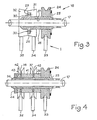
- FIG. 3 shows an embodiment of the short-circuit contact device 18 comprising a guide and short-circuiting roller 24 having a peripheral groove with a "V" section like the roller 7, this guide roller 24 carrying a complementary short-circuit device
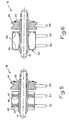
- FIGS. 4 to 6 show different variants of this complementary short-circuit device.
- the roller 24 is fixed to a long hub and includes a device 25 for complementary contacts, identical to the device 7A for the roller 7, this device 25 being fixed to the flat face of the roller facing the free end of the rod 17.
- the roller 24 is fixed on a long hub 26 substantially cylindrical, projecting from the roller 24 in the direction of the unused part of the inductor, in this case in the direction of the center of the spiral.
- the hub 26 has practically the same internal diameter as the roller 7, however, in order to reduce the friction on the rod 17, a recess 27 is practiced on a large part of its internal face, leaving only contact zones with this rod 17 'at the ends of the hub.
- the length of the hub 26 is approximately twice the pitch of the spiral.
- the hub 26 has, near its free end, a shoulder 28 forming a fixing flange.
- the flat face 29 of the shoulder 28, facing the center of the spiral when the device 28 is in place on the rod 17, is located about 1.5 times the pitch of the spiral from the center of the roller 24.
- two identical complementary short-circuiting devices 31 and 32 are each in the form of a cylindrical pot with a side wall which widens slightly towards the outside, for example at an angle of about 20 °. the bottom of this pot being pierced with an axial hole of diameter substantially equal to the outside diameter of the hub 26, and of holes necessary for fixing on the shoulder 28.
- the height of the side wall of the pot is slightly greater than half pitch of the spiral formed by the inductor 1.
- the diameter of the side wall, at its free end, is slightly greater than the distance between the axis of the rod 17 and the face 2 of the inductor 1.
- These pots, or at least their side wall, are made of electrically conductive elastic material, for example chrysocale or beryllium bronze. Due to the dimensions of the devices 31 and 32 specified above, and their arrangement in the device 18, when the roller 24 rolls on the upper face of a spiral section 33 of the inductor 1, the lateral faces of the devices 31 and 32 also roll on the upper faces of the two following spiral sections 34 and 35 at one turn and at two turns of the roller 24 respectively.
- the elasticity and the dimensions of the devices 31 and 32 mean that these devices are always in contact with the spiral, even when its pitch is not regular and its surface 2 is not absolutely flat: in one embodiment, the devices 31 and 32 can accept variations in height of ⁇ 0.5 mm from the face upper of the spiral sections compared to the average position of this face.
- the variant embodiment of the short-circuit device 18 shown in FIG. 4 comprises a hub 36, on which the roller 24 is fixed, a little longer than the hub 26 in FIG. 3.
- the free end of the hub 26 is externally threaded.
- two short-circuiting elements 37 and 38 are fixed, each formed using two identical cups made of electrically conductive elastic material, for example chrysocale or beryllium bronze, these cups having substantially the shape of plates.
- the radius of the bottoms of these cups is slightly less than the distance between the axis of the rod 17 and the upper face 2 of the inductor, while the edges of these cups flare outward, at an angle of about 60 ° relative to the bottoms, the height of these edges being approximately equal to said thickness of the section of the inductor 1.
- the bottoms of these cups are, of course, pierced with axial holes of diameter substantially equal to the outside diameter of the hub 36 on which these cups are threaded.
- the cups of the devices 37 and 38 are held in place by means of cylindrical sleeves referenced 39 to 43 and disposed respectively between the roller 24 and the cup facing it of the device 37, between the two cups of the device 37, between the cups facing the devices 37 and 38, between the two cups of the device 38, and beyond the device 38, the set of cups and sleeves being tightened against the roller 24 using a nut 44 screwed onto the threaded end of the hub 36.
- the lengths of the sleeves 39 to 43 are determined so that the outer faces of the flared edges of the cups forming the devices 37 and 38 are in contact with the spiral when the spiral is regular and flat, these cups then being barely deformed and firmly held in contact with the spiral due to their elasticity, the roller 24 being correctly applied against the spiral as specified above.
- the wall thickness of the sleeves 39 to 43 is determined so that the cups of the devices 37 and 38 are firmly held on the hub 36 without the elasticity of the peripheral part of their bottoms and the elasticity of their edges being thereby affected, thus allowing them to always be in good contact with the spiral, as long as this spiral is not too irregular.
- the device of FIG. 4 does not make it possible to compensate for irregularities in the pitch of the spiral as well as the device of FIG. 3, but admits a greater variation in the height of the turns than the latter: when the pitch is too irregular l one of the two cups of the contact device 37 or 38 loses contact with the spiral and the quality of the electrical contact decreases, while when the height of the upper face of the spiral varies (defect of flatness of the face 2 of the inductance), the edges of the two cups move apart or approach each other while both remaining in contact with the spiral.
- the variant embodiment of the device 18 shown in the figure comprises, like that of FIG. 4, a long hub 45 supporting the roller 24, the hub 45 being identical to the hub 36, with the difference that its free end is not threaded.
- the free end of the hub 45 supports a sleeve 46 by means of two series of springs 47 and 48 each comprising several cylindrical springs whose axes are arranged radially in the same plane and regularly spaced, these springs being fixed to the hub 45 and to the sleeve 46, and these two series of springs being located substantially at the level of the spiral section 34 and of the section 35, respectively.
- the outside radius of the sleeve 46 is slightly greater than the average distance between the axis of the rod 17 and the upper face of the inductor 1, and its length is approximately equal to twice the pitch of the spiral, this sleeve being disposed almost tangent to the roller 24.
- the sleeve 46 may be rigid, for example made of brass, or else elastically deformable, for example made of chrysocale.
- the single sleeve 46 can be replaced by two short sleeves of the same external diameter as it, and each having half its length, arranged side by side and making contact with the spiral sections 34 and 35 respectively.
- the variant embodiment of the contact device 18 shown in FIG. 6 comprises the same hub 45 supporting the roller 24 and the same sleeve 46 as the embodiment of FIG. 5.
- the series of springs 47 and 48 are replaced, in the embodiment of FIG. 6, by a single spring 49 made from a leaf spring with folded side edges, on the same side of the leaf, semi-circularly, this spring then being wound around the hub, the ends of the folded edges coming into contact with the hub on which they are fixed by any suitable means.
- the spring 49 thus obtained is fixed to the sleeve 46 by its outer face of circular cylindrical shape.
- the radius of the curved edges 50 of the leaf spring, before the fitting of the sleeve 46, is determined in such a way that when this spring is fixed to the hub 45, its cylindrical outer face has a diameter slightly greater than the diameter inside of the sleeve 46.
- the long sleeve 46 of FIG. 6 can be replaced by two short sleeves.
- the contact devices 18 of FIGS. 3 to 6 can only short-circuit one and a half turns beyond the main roller 7 and be reduced accordingly.
- FIG. 7 an alternative embodiment of the second roller and the hub.
- the second roller 51 is similar to the roller 24, except that its internal diameter is practically equal to the diameter of the rod 17.
- the hub 52 has at one of its ends a circular shoulder 53 allowing fix it on a flat lateral face of the roller 51.
- the total length of the hub 52 is practically equal to the length of the hub protruding from the roller 24 in the variant embodiments of FIGS. 3 to 6, the other characteristics of the hub 52 remaining the same as in these variant embodiments.
- the short-circuiting device 18 shown in FIG. 8 comprises a main roller 54 and a complementary roller 55.
- the rollers 54 and 55 both have the same thickness and a convex peripheral profile, advantageously semi-circular and of the same external shape.
- the maximum radius of these two rollers measured in a plane perpendicular to the axis of the rod 17 on which these two rollers move, is greater than the distance between said axis of the rod and the upper face 2 of the spiral.
- the maximum radius of the roller 55 is however slightly greater than that of the roller 54.
- the thickness of the two rollers 54 and 55 is greater than or equal to the pitch of the spiral.
- the diameter of the axial hole of the roller 54 is practically equal to the diameter of the rod 17, while the roller 55 is pierced with an axial hole of larger diameter in order to accommodate a bearing 56 therein having springs urging the roller 55 towards a position centered with respect to the axis of the rod 17.
- the roller 54 By its surface in contact with the turn section 33, the roller 54 short-circuits the first half turn of the unused part, and with its surface in contact with the turn section 34, it short-circuits the next turn.
- the roller 55 by its surface in contact with the turn section 35, again short-circuits a next turn.
- the roller 54 is applied firmly against the inductor 1 by the aforementioned spring acting on the shaft 21, by means of the rod 17, while the roller 55, slightly larger than the roller 54, is applied against the inductance 1 by the force of the springs of the bearing 56 which are compressed in their part lying between the shaft 17 and the inductance 1.
- the roller 55 is however not absolutely necessary in all cases, all the more so as the roller 54 short-circuits a turn and a half.
- roller 54 it is of course possible to replace the roller 54 with the roller 24, or else to replace the roller 55 with one of the devices 31, 32, 37, 38 or 46 by mounting them on a suitable hub fixed to the roller 54.
- the inductance can have any other known shape, for example a cylindrical helical shape, the main electrical contact and short-circuit devices then being modified accordingly in an obvious manner for the person skilled in the art on reading. from the description above.
- FIG. 9 shows examples of resonance frequency curves F of inductance 1 as a function of its number of turns or of its inductive value N.
- Curve A is that of the resonance frequency of the useful part of the inductor, which is always greater than twice the frequency of use (to also avoid resonance on harmonic 2 of the frequency of use). This curve is a function of the geometry of the inductance.
- Curve B is that of the resonance frequency of the unused part of the inductor. This curve is a function of the number of short-circuit rollers.
- the device of the invention comprises a means for short-circuiting at least the first half-turn of the unused part of the variable inductor, by means of the rod supporting the main roller 7, and forms thus a short circuit loop which absorbs the maximum field radiated by the useful part of the inductor, thus avoiding the excitation of the unused part.
- a side effect of this short circuit is to reduce the unused part, which rejects its resonances at higher frequencies.
- FIGS. 10 to 12 show another embodiment of the variable inductor and of its protection device according to the invention.
- the inductor 57 is in helical cylindrical form, produced, in a manner known per se, from a metal tube for example.
- a shaft 58 driven by a suitable drive mechanism (not shown) is disposed inside the inductor 57, its axis 59 being coincident with that of the inductor.
- the shaft 58 made of electrically conductive metal, is solid and has a circular section.
- a hub 61 made of electrically conductive material, substantially cylindrical, provided with friction bearings 62, 63, can move longitudinally on the shaft 58.
- the hub 61 is rotated by the shaft 58 thanks to a key 64, integral from the hub 61, projecting from the hub towards its center, the projecting part of the key 64 having a shape complementary to that of the groove 60 in which it engages.
- the key 64 is guided by the groove 60 in which it moves with gentle friction, making the shaft 58 and the hub 61 integral in rotation, while allowing the hub to move longitudinally on the shaft.
- the bearings 62, 63 of annular shape, are fixed to the ends of the hub 61, and allowing the hub 61 to move with gentle friction on the shaft.
- At least two electrical contact devices are fixed on an end face of the hub 61 ensuring good electrical contact between the hub 61 and the shaft 58, these contact devices being for example in the form of curved leaf springs, one end is fixed to the hub and the other end of which carries a contact grain, for example in silver, this contact grain being applied firmly by the spring to the shaft 58.
- This main contact device 68 essentially consists of a contact pulley 69 supported by a stirrup 70 fixed on the flat 67.
- the groove of the pulley 69 has a shape such that it allows it to roll easily on the face facing the axis 59 of the tube constituting the inductor 57, while ensuring very good electrical contact between the tube and the pulley.
- the pulley 69 comprises on each of its lateral faces (cheeks) an electrical contact spring 71, 71A being for example in the form of a cup, the curved central part of which rests against the adjacent face of the stirrup 70.
- the springs 71, 71A improve the electrical contact between the pulley 69 and the stirrup 70.
- the axis 72 of the pulley 69 can move radially in oblong holes in the stirrup 70 over a short distance by being strongly stressed towards the inductance by pressure springs 73, 74 bearing on the bracket 70 (see construction details in FIG. 11 which relates to the production, similar, of the first short-circuit contact).
- the pulley 69 is always applied firmly against the inductor 57, even if the latter has irregularities in diameter.
- the first electrical short-circuit contact 75 is fixed on the hub, diametrically opposite to the main contact 68.
- the part of the hub 61 on which the short-circuit contacts are fixed is located on the side of the unused part of the inductor 57 relative to the main contact 68.
- the contact 75 similar to the contact 68, comprises a stirrup 76 supporting a pulley 77 whose axis 78 can move radially in oblong holes such as the hole 79 visible in FIG. 11.
- the axis 78 is biased towards the inductor (that is to say radially towards the outside of the inductor) by pressure springs 80, 81.
- Cup-shaped springs 82, 82A similar to the springs 71, 71 A, provide electrical contact between the pulley 77 and the stirrup 76.
- the stirrup 76 of the contact 75 is fixed on a flat 83 formed on the hub 61.
- the second electrical short-circuit contact 84 is fixed to a boss 85 formed on the hub 61, near the end of this hub opposite to that supporting the main contact 68.
- This contact 84 extends for example along a parallel radial to the radial passing through the axis of the contact 75, thus short-circuiting an entire turn of the unused part of the inductor 57 beyond the contact 75.
- the second short contact -circuit can also short-circuit yet another whole turn, for that, it is enough to extend it sufficiently so that it is applied to the next turn of the inductor.
- the contact 84 comprises a leaf spring 86 in the shape of a "U", one branch of which is fixed on the boss 85 and the other branch of which bears a contact grain 87, in silver for example, applied against the inductor 57.
- the spring 86 is of course provided for correctly applying the contact gain 87 on the inductor 57 at all points of this inductor.
- Contact 84 could in another embodiment be arranged differently with respect to contact 75, for example at a half-turn of the latter, or at more than one turn, and could short-circuit all the rest of the unused part of inductance.
Landscapes
- Engineering & Computer Science (AREA)
- Power Engineering (AREA)
- Coils Or Transformers For Communication (AREA)
- Transmitters (AREA)
Claims (10)
Applications Claiming Priority (2)
| Application Number | Priority Date | Filing Date | Title |
|---|---|---|---|
| FR8205244A FR2524192B1 (fr) | 1982-03-26 | 1982-03-26 | Dispositif de protection pour inductance variable de forte puissance a haute frequence |
| FR8205244 | 1982-03-26 |
Publications (2)
| Publication Number | Publication Date |
|---|---|
| EP0090703A1 EP0090703A1 (de) | 1983-10-05 |
| EP0090703B1 true EP0090703B1 (de) | 1987-02-04 |
Family
ID=9272452
Family Applications (1)
| Application Number | Title | Priority Date | Filing Date |
|---|---|---|---|
| EP19830400536 Expired EP0090703B1 (de) | 1982-03-26 | 1983-03-15 | Schutzeinrichtung für variable hochfrequente Induktanz hoher Leistung |
Country Status (6)
| Country | Link |
|---|---|
| EP (1) | EP0090703B1 (de) |
| JP (1) | JPS58176906A (de) |
| CA (1) | CA1210100A (de) |
| DE (1) | DE3369766D1 (de) |
| DK (1) | DK131483A (de) |
| FR (1) | FR2524192B1 (de) |
Cited By (1)
| Publication number | Priority date | Publication date | Assignee | Title |
|---|---|---|---|---|
| CN107464654A (zh) * | 2017-09-27 | 2017-12-12 | 广州赛宝计量检测中心服务有限公司 | 一种宽频带高稳定高频电感器 |
Families Citing this family (1)
| Publication number | Priority date | Publication date | Assignee | Title |
|---|---|---|---|---|
| CN114694920A (zh) * | 2022-04-25 | 2022-07-01 | 武汉联影生命科学仪器有限公司 | 一种可调电感和用于磁共振的发射电路 |
Family Cites Families (1)
| Publication number | Priority date | Publication date | Assignee | Title |
|---|---|---|---|---|
| DE2165814A1 (de) * | 1971-12-29 | 1973-07-05 | Licentia Gmbh | Einrichtung zum kurzschliessen des nicht aktiven spulenteiles eines spiralvariometers |
-
1982
- 1982-03-26 FR FR8205244A patent/FR2524192B1/fr not_active Expired
-
1983
- 1983-03-15 DE DE8383400536T patent/DE3369766D1/de not_active Expired
- 1983-03-15 EP EP19830400536 patent/EP0090703B1/de not_active Expired
- 1983-03-23 DK DK131483A patent/DK131483A/da not_active Application Discontinuation
- 1983-03-25 CA CA000424457A patent/CA1210100A/en not_active Expired
- 1983-03-26 JP JP4972783A patent/JPS58176906A/ja active Pending
Cited By (1)
| Publication number | Priority date | Publication date | Assignee | Title |
|---|---|---|---|---|
| CN107464654A (zh) * | 2017-09-27 | 2017-12-12 | 广州赛宝计量检测中心服务有限公司 | 一种宽频带高稳定高频电感器 |
Also Published As
| Publication number | Publication date |
|---|---|
| FR2524192A1 (fr) | 1983-09-30 |
| DK131483A (da) | 1983-09-27 |
| DK131483D0 (da) | 1983-03-23 |
| CA1210100A (en) | 1986-08-19 |
| JPS58176906A (ja) | 1983-10-17 |
| FR2524192B1 (fr) | 1986-10-10 |
| EP0090703A1 (de) | 1983-10-05 |
| DE3369766D1 (en) | 1987-03-12 |
Similar Documents
| Publication | Publication Date | Title |
|---|---|---|
| EP1392987B1 (de) | Schwingungstilger | |
| CA2416012C (fr) | Dispositif d'amortissement de vibrations | |
| FR2651608A1 (fr) | Antenne plane. | |
| EP0662736B1 (de) | Drehender elektrischer Schleifring mit Mehrdrahtbürsten | |
| EP0961344A1 (de) | Funkkommunikationseinrichtung und eine Schlitz-Schleifenantenne | |
| EP0889541A1 (de) | Wendelantenne mit variabler Länge | |
| FR2711277A1 (fr) | Antenne du type pour dispositif radio portable, procédé de fabrication d'une telle antenne et dispositif radio portable comportant une telle antenne. | |
| FR2837985A1 (fr) | Antenne receptrice morcelee | |
| EP1886382A2 (de) | Elektronische entität mit magnetantenne | |
| FR2597266A1 (fr) | Antenne a large bande | |
| FR2535532A1 (fr) | Antenne interieure pour un recepteur de television | |
| EP0308935B1 (de) | Armbandantenne für Radioempfänger, der in eine Uhr eingebaut ist | |
| EP0090703A1 (de) | Schutzeinrichtung für variable hochfrequente Induktanz hoher Leistung | |
| FR2895638A1 (fr) | Dispositif inducteur a bobinages individuels multiples pour foyer de cuisson par induction | |
| EP0553025A1 (de) | Vorrichtung zum geradlinigen Aufbringen eines dünnen Metalldrahtes auf der Oberfläche des thermoplastischen Films einer Verbundglasscheibe | |
| FR2546342A1 (fr) | Collecteur de courant | |
| FR3116159A1 (fr) | Antenne de communications radio constituée d’un fil métallique rigide préalablement cintré, structure de support et terminal de paiement correspondant | |
| EP1607761A1 (de) | Multifrequenz-Stromeinspeisung und Spule und NMR-Spektrometer mit einer solchen Stromeinspeisung | |
| EP1350285A1 (de) | Elektromagnetische sonde | |
| EP0007275B1 (de) | Veränderliche Induktivität und Sender mit solch einer Induktivität | |
| EP0487388B1 (de) | Drossel, insbesondere für Kurzwellen | |
| EP0442411B1 (de) | Konische Feder für einen elektrischen Kontakt | |
| WO1987006396A1 (fr) | Dispositif de contact electrique a balai pour moteur electrique a commutateur cylindrique | |
| EP3029766B1 (de) | Kontaktlose antenne, halterungsstruktur und entsprechender anschluss | |
| BE521287A (de) |
Legal Events
| Date | Code | Title | Description |
|---|---|---|---|
| PUAI | Public reference made under article 153(3) epc to a published international application that has entered the european phase |
Free format text: ORIGINAL CODE: 0009012 |
|
| AK | Designated contracting states |
Kind code of ref document: A1 Designated state(s): CH DE FR GB IT LI NL |
|
| 17P | Request for examination filed |
Effective date: 19840517 |
|
| GRAA | (expected) grant |
Free format text: ORIGINAL CODE: 0009210 |
|
| AK | Designated contracting states |
Kind code of ref document: B1 Designated state(s): DE FR GB |
|
| REF | Corresponds to: |
Ref document number: 3369766 Country of ref document: DE Date of ref document: 19870312 |
|
| PG25 | Lapsed in a contracting state [announced via postgrant information from national office to epo] |
Ref country code: FR Free format text: LAPSE BECAUSE OF NON-PAYMENT OF DUE FEES Effective date: 19871130 |
|
| PG25 | Lapsed in a contracting state [announced via postgrant information from national office to epo] |
Ref country code: DE Effective date: 19871201 |
|
| PLBE | No opposition filed within time limit |
Free format text: ORIGINAL CODE: 0009261 |
|
| STAA | Information on the status of an ep patent application or granted ep patent |
Free format text: STATUS: NO OPPOSITION FILED WITHIN TIME LIMIT |
|
| GBPC | Gb: european patent ceased through non-payment of renewal fee | ||
| 26N | No opposition filed | ||
| REG | Reference to a national code |
Ref country code: FR Ref legal event code: ST |
|
| PG25 | Lapsed in a contracting state [announced via postgrant information from national office to epo] |
Ref country code: GB Effective date: 19881122 |