EP0090724A1 - Vorrichtung zum Verbinden von optischen Fasern und Verfahren zu deren Benutzung - Google Patents
Vorrichtung zum Verbinden von optischen Fasern und Verfahren zu deren Benutzung Download PDFInfo
- Publication number
- EP0090724A1 EP0090724A1 EP83400593A EP83400593A EP0090724A1 EP 0090724 A1 EP0090724 A1 EP 0090724A1 EP 83400593 A EP83400593 A EP 83400593A EP 83400593 A EP83400593 A EP 83400593A EP 0090724 A1 EP0090724 A1 EP 0090724A1
- Authority
- EP
- European Patent Office
- Prior art keywords
- flange
- elastic
- optical fiber
- optical fibers
- elastically deformable
- Prior art date
- Legal status (The legal status is an assumption and is not a legal conclusion. Google has not performed a legal analysis and makes no representation as to the accuracy of the status listed.)
- Granted
Links
Images


Classifications
-
- G—PHYSICS
- G02—OPTICS
- G02B—OPTICAL ELEMENTS, SYSTEMS OR APPARATUS
- G02B6/00—Light guides; Structural details of arrangements comprising light guides and other optical elements, e.g. couplings
- G02B6/24—Coupling light guides
- G02B6/36—Mechanical coupling means
- G02B6/38—Mechanical coupling means having fibre to fibre mating means
- G02B6/3801—Permanent connections, i.e. wherein fibres are kept aligned by mechanical means
- G02B6/3806—Semi-permanent connections, i.e. wherein the mechanical means keeping the fibres aligned allow for removal of the fibres
Definitions
- the present invention relates to a device for connecting optical fibers.
- Attenuation of the order of a few decibels per kilometer are very sensitive to constraints.
- the attenuation produced at the level of a connection can be multiplied by a factor which can go up to approximately 4 due to the contribution of stresses on the fibers.
- the present invention relates to an optical fiber connection device making it possible to minimize the contribution of stresses on the optical fibers at the connection.
- the device according to the invention is characterized in that it comprises a reference surface intended to have end-to-end at least one pair of optical fibers and an elastic flange to hold the optical fibers in place under the action of a transverse elastic force of given intensity.
- the reference surface may include at least one groove adapted to the shape of the fibers. Said groove can be V-shaped.
- the elastic flange may include an elastically deformable central region and a peripheral region having fixing means.
- This peripheral region can be elastically non-deformable so as to serve as a stop when the elastic flange is tightened.
- the elastically deformable central region can be added to the elastic flange.
- the device may include a flat flange to hold at least one optical fiber located on one side of the connection.
- the device can consist of cylindrical outer contour parts arranged in a housing formed in two half-shells.
- the elastic flange may have two lateral flanges connected to each other at their ends and comprising in their central part and over a given length 1, an elastically deformable membrane comprising two parallel walls extending by walls. converging inclines connected together by a flat wall intended to bear against the optical fibers when the device is mounted.
- the method comprises a step where the ends of the optical fibers to be connected are prepared, a step where at least one first optical fiber is placed on the reference surface, a step where a second optical fiber is placed opposite each first optical fiber, optionally a step where the elastic flange is positioned without clamping so as to position the optical fibers while leaving a freedom of movement in translation at least for each second optical fiber, a step where the end of each second optical fiber is abutted against the end of each first optical fiber and a step where the elastic strap is tightened in position.
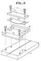
- a support 1 is provided with a V 2 for positioning optical fibers.
- the V is the optimal shape for a reference surface.
- the fiber is kept centered by geometric contact with two reference points.
- the connection is obtained by means of a so-called elastic flange 4 and possibly a flange 3 which are intended to be screwed into threads 6 of the support 1 by means of screws 5.
- the flange 3 is in the form of a flat plate provided with two bores 11.
- the elastic flange 4 assumes in section the general shape of a U having a central branch 7 and two lateral branches 8 bored at 9.
- the two branches 8 of the U join by an elastic and thin wall 10 of length L and thickness e l .
- This wall is arched outwards and protrudes by a distance of flat reference surfaces formed by the ends 8 ′ of the U.
- the arched shape of the wall 10 makes it possible to direct the fibers at the bottom of the V and to avoid overlapping of the fibers.
- the first operation consists in preparing one of the optical fibers. To do this, the outer protective sheath is removed over a short length at the end thereof, while retaining the optical sheath. The fiber thus prepared is positioned in the V marked in 2 and it is held in position by tightening the flange 3 at a level where the sheath has not been removed. As the fiber is still coated with its mechanical protection sheath, for example in epoxy or silicone, the tightening of the flange 3 does not bring any constraints at the level of the fiber itself. Furthermore, the presence of the flange 3 facilitates the establishment of the connection, since it maintains in position the first fiber during the presentation of the second fiber.
- the flat flange can be subsequently dismantled.
- the elastic flange 4 is screwed onto the support l, the two optical fibers are held in position in the V by an elastic restoring force due to the elastic deformation of the wall 10. This force is exerted on the stripped part of the fibers , which must therefore correspond to the width of the elastic flange 4.
- the parameters which define the wall 10 are chosen in such a way that the force applied to the fibers is low enough not to produce such drawbacks.
- the elastic flange 4 has been produced from an unreinforced polycarbonate (for example MAKROLON brand from the company BAYER). It has a density of 1.2 to 1.24 and a modulus of elasticity of 22,000 Kg / cm2. It is easily moldable and has good flexural strength and good dimensional stability.
- the length L of the wall 10 is 7 mm, its thickness e l of about 0.35 mm, and the excess of, of the order of 0.2 mm, for an optical fiber of 125 microns in diameter protruding 20 to 40 microns from a V-shaped groove (see Figure 2b).
- connection On a measurement bench, 50 connections were tested, performed as above, from the cleavage of a fiber with a hard optical sheath of a cable and placed end to end at both ends. For 46 of these, the attenuation due to the connection was less than 0.1 dB, that is to say practically not measurable.
- connection can therefore be used as a reference for a test bench for attenuation of the connectors.
- the steel chosen is a spring steel of Cu-Be alloy
- the thickness e 2 is 0.2 mm
- the projection relative to the lower part of the flange 21 of 0.2 mm.
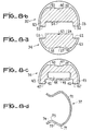
- FIG. 6a and 6b which show the flange 21 respectively in side view and from above, it takes the shape of a U whose central branch 26 is thicker than the two lateral branches 27 so as to position the elastic piece 20.
- the lateral branches 27 each have a bore 29 and a chamfer 28 located on the internal side of each branch 27. The purpose of this chamfer 28 is to let the junction zone pass between the flat portion 24 and the arched portion 25 of the part. elastic 20.
- the arched portion 25 of the elastic piece 20 exceeds by a given amount the lower part 27 ′ of the flange 21.
- the elastic force of support on the optical fibers is thus determined by the mechanical characteristics of the assembly as in the case of FIG.
- the realization of the connection of the optical fibers implements the same steps as in the case of FIG.
- the flange 35 ( Figure 8b), which plays the role of the flange 3 of Figure la, has a lower flat face 52 in which is formed a groove 54 whose width corresponds to that of the upper surface 64 of the support 34, the lower surface 52 also coming into abutment in the notches 62.
- the central part of the flange 35 has, as for the support 34, a cylindrical contour and its upper part consists of a flat 51 provided with a notch 51 'in the form of V intended to receive a branch of a clip 37.
- the flange 35 is provided with a cylindrical contour 53, the diameter of which greater than that of the central part 50 corresponds to the internal diameter of the half shell 32.
- the central part 40 of the elastic flange 36 has a generally cylindrical outline except at its upper part, which has a flat 41 in which is formed a notch 41 ′ allowing to receive a branch of a clip 37.
- the central part 40 has at its lower part a cavity 44 which borders the elastic membrane 45.
- a cylindrical contour 43 is formed, the outside diameter of which is greater than that of the central part 40, corresponds to the inside diameter of the half - shell 32.
- connection of two optical fibers implements the same operations as in the case of the preceding embodiments, the flanges 35 and 36 being fixed to the support 34 by means of a clip 37 shown in FIG. 8d.
- This has a central portion 70 curved to a diameter corresponding to that of the central parts 40, 50 and 60.
- the central part 70 has on each side an elbow 71 which is extended by a straight part 72 directed inwards.
- Each straight part 72 is extended by a bend 73 and an end portion 74 directed outwards, the assembly 72, 73 and 74 being intended to be housed in the V-shaped notches 41 ′, 51 ′ and 61 ′ .
- FIGS. 9a and 9b show respectively in top view and in section a support element for optical fiber intended for multiple connection and comprises a block 80 of width 1 and length L 1 on the upper surface of which grooves 82 are formed. V-shaped bordered at each end by grooves 81 also V-shaped but of larger size so as to facilitate the presentation of the optical fibers.
- This support element is intended to be inserted in a central support shown in section in FIG. 10.
- This comprises a block 83 having a flat upper surface 84 in which is formed a groove 85 whose width 1 corresponds to that of the support element described above.
- the upper surface 84 also includes threads 84 'intended for fixing the flange or flanges of the connection device.
- FIGS. Ua to llc respectively represent a top view, in section AA and in section BB, an embodiment of an elastic flange intended to be mounted on the support described in FIG. 10.
- the elastic flange has two lateral flanges 90. These are interconnected at each of their ends by sections 91 of rectangular shape in which are formed bores 92. These sections 91 do not extend to the upper surface lateral flanges 90 in order to leave a space available for the screw heads in the bores 92.
- an elastically deformable membrane which extends from a flange 90 to to the other. This consists of two parallel walls 93 each of which extends downward the side edges 90.
- the vertical walls 93 are extended by converging inclined walls 94 which are connected together by a flat portion 95.
- This portion 95 is arranged in such a way that it protrudes from a distance d 'from the lower plane 91' of the sections 91. In this way, when the elastic flange is mounted on the support 83, by mounting the screws in the threads 84 'through the bores 92 , the flat portion 95 presses the optical fibers in the grooves 82 over the entire length 1.
- the connection is advantageously carried out in the following manner.
- the fibers at the end of two cables to be connected are mounted in position on a lateral support (not shown) and provided with V-shaped grooves having the same spacing as those of the central support. They are prepared using a tool for collective breakage of optical fibers as described in French patent application 80 16 917 filed on July 31, 1980 by the Applicant.
- Each lateral support is made in such a way deny that the fibers protrude after breaking a quantity precisely determined.
- the lateral supports are then mounted on each side of the block 83 of the central support.
- the optical fibers are then positioned opposite one another. It only remains to mount the elastic flange (FIGS. 11 a to 11 c) with possible interposition of an index liquid.
- the elastic flange shown in Figures 11a to 11c can be produced by molding.
- the material is an uncharged polycarbonate (MAKROLON brand from the company BAYER).
- the elastic membrane has a length 1 equal to II mm, a constant thickness e l equal to 0.3 mm, the portion 95 has a width of 1.5 mm for a spacing of 7 mm between the side walls 93, and the protrusion d 'is equal to 0.2 mm for optical fibers of 125 microns in diameter and protruding from 20 to 40 microns from the V-shaped grooves
- an elastic flange comprising an elastically deformable central region and a non-elastically deformable peripheral region which serves as a stop when tightening the elastic flange.
- the clamping of the flange is elastic and the pressing force is sufficient to prevent any movement from one fiber to another without generating constraints liable to alter the quality of the transmission.
- the clamping of the flange is dynamometric and the bearing force on the fibers remains constant so that the quality of the transmission by the fibers remains unaltered.
- the invention is not limited to the embodiments explicitly described and exemplified.
- other materials can be used to make the flanges and in particular the elastic flanges.
- all elastic materials with good mechanical properties can be used.
Landscapes
- Physics & Mathematics (AREA)
- General Physics & Mathematics (AREA)
- Optics & Photonics (AREA)
- Mechanical Coupling Of Light Guides (AREA)
Applications Claiming Priority (2)
| Application Number | Priority Date | Filing Date | Title |
|---|---|---|---|
| FR8205441A FR2524654B1 (fr) | 1982-03-30 | 1982-03-30 | Dispositif de raccordement de fibres optiques et procede le mettant en oeuvre |
| FR8205441 | 1982-03-30 |
Publications (2)
| Publication Number | Publication Date |
|---|---|
| EP0090724A1 true EP0090724A1 (de) | 1983-10-05 |
| EP0090724B1 EP0090724B1 (de) | 1987-02-04 |
Family
ID=9272566
Family Applications (1)
| Application Number | Title | Priority Date | Filing Date |
|---|---|---|---|
| EP19830400593 Expired EP0090724B1 (de) | 1982-03-30 | 1983-03-22 | Vorrichtung zum Verbinden von optischen Fasern und Verfahren zu deren Benutzung |
Country Status (3)
| Country | Link |
|---|---|
| EP (1) | EP0090724B1 (de) |
| DE (1) | DE3369734D1 (de) |
| FR (1) | FR2524654B1 (de) |
Cited By (11)
| Publication number | Priority date | Publication date | Assignee | Title |
|---|---|---|---|---|
| FR2556847A1 (fr) * | 1983-12-16 | 1985-06-21 | Socapex | Dispositif de connexion semi-permanent pour fibres optiques et procede pour sa mise en oeuvre |
| FR2579772A1 (fr) * | 1985-03-29 | 1986-10-03 | Socapex | Duplexeur optique a raccordement optique semi-permanent integre |
| US4615097A (en) * | 1983-10-05 | 1986-10-07 | Cabloptic S.A. & Fondation Suisse pour la Recherche en Microtechnique | Apparatus for precise positioning of optical components |
| FR2586304A1 (fr) * | 1985-08-13 | 1987-02-20 | Radiall Ind | Dispositif pour etablir, de facon reversible, une connexion entre deux fibres optiques, fiches mobiles et dispositif de fixation pour ce dispositif, et procede de preparation d'une terminaison de fibre optique adapte |
| FR2593294A1 (fr) * | 1986-01-23 | 1987-07-24 | Alsthom Cgee | Connecteur pour fibres optiques |
| EP0154689B1 (de) * | 1984-02-09 | 1990-05-02 | Siemens Aktiengesellschaft | Vorrichtung zum lösbaren Ankoppeln eines Lichtwellenleiters an ein optoelektronisches Bauelement |
| EP0462710A1 (de) * | 1990-06-20 | 1991-12-27 | Hughes Aircraft Company | Halter für Glasfasern |
| WO1999042876A1 (de) * | 1998-02-23 | 1999-08-26 | Huber & Suhner Ag | Positioniervorrichtung zum positionieren und fixieren von optischen fasern sowie steckverbinder mit einer solchen positioniervorrichtung |
| EP0806688B1 (de) * | 1996-05-09 | 2003-03-26 | France Telecom | Zentrierelement, Verfahren für die Verbindung einer Anzahl von Fasern an eine Mehrkernfaser und so hergestellte Koppel-/Verteilervorrichtung |
| US7512305B2 (en) * | 2006-02-08 | 2009-03-31 | Bookham Technology Plc | Precision optical fiber clamp |
| CN102073105A (zh) * | 2010-12-07 | 2011-05-25 | 福州高意通讯有限公司 | 一种光纤夹持器 |
Citations (7)
| Publication number | Priority date | Publication date | Assignee | Title |
|---|---|---|---|---|
| US3885859A (en) * | 1974-06-24 | 1975-05-27 | Northern Electric Co | Optical fibre connectors |
| US4102561A (en) * | 1975-07-02 | 1978-07-25 | Corning Glass Works | Optical waveguide connector |
| GB1520679A (en) * | 1977-02-18 | 1978-08-09 | Bicc Ltd | Jointing optical fibres |
| GB2009440A (en) * | 1977-11-24 | 1979-06-13 | Comp Generale Electricite | Fibre-to-fibre connector for miltifibre optical fibre cables |
| WO1980000619A1 (en) * | 1978-09-01 | 1980-04-03 | Gte Sylvania Inc | Optical fiber connector |
| EP0021871A1 (de) * | 1979-06-08 | 1981-01-07 | Thomson-Csf | Verfahren zum Einbau einer optischen Faser in eine Zwinge und Zwinge die nach Ausführung des Verfahrens erhalten wird |
| FR2487812A1 (fr) | 1980-07-31 | 1982-02-05 | Socapex | Outillage de cassure collective de fibres optiques |
Family Cites Families (1)
| Publication number | Priority date | Publication date | Assignee | Title |
|---|---|---|---|---|
| FR2446496A1 (fr) * | 1977-11-24 | 1980-08-08 | Comp Generale Electricite | Fiche de connecteur fibre a fibre pour cable optique multifibre |
-
1982
- 1982-03-30 FR FR8205441A patent/FR2524654B1/fr not_active Expired
-
1983
- 1983-03-22 DE DE8383400593T patent/DE3369734D1/de not_active Expired
- 1983-03-22 EP EP19830400593 patent/EP0090724B1/de not_active Expired
Patent Citations (7)
| Publication number | Priority date | Publication date | Assignee | Title |
|---|---|---|---|---|
| US3885859A (en) * | 1974-06-24 | 1975-05-27 | Northern Electric Co | Optical fibre connectors |
| US4102561A (en) * | 1975-07-02 | 1978-07-25 | Corning Glass Works | Optical waveguide connector |
| GB1520679A (en) * | 1977-02-18 | 1978-08-09 | Bicc Ltd | Jointing optical fibres |
| GB2009440A (en) * | 1977-11-24 | 1979-06-13 | Comp Generale Electricite | Fibre-to-fibre connector for miltifibre optical fibre cables |
| WO1980000619A1 (en) * | 1978-09-01 | 1980-04-03 | Gte Sylvania Inc | Optical fiber connector |
| EP0021871A1 (de) * | 1979-06-08 | 1981-01-07 | Thomson-Csf | Verfahren zum Einbau einer optischen Faser in eine Zwinge und Zwinge die nach Ausführung des Verfahrens erhalten wird |
| FR2487812A1 (fr) | 1980-07-31 | 1982-02-05 | Socapex | Outillage de cassure collective de fibres optiques |
Non-Patent Citations (2)
| Title |
|---|
| ABSTRACT OF NEW TECHNOLOGY FROM THE AIR FORCE SYSTEMS COMMAND, no. NTN-78/0446, 1978, USA * |
| IBM TECHNICAL DISCLOSURE BULLETIN, vol. 22, no. 2, juillet 1979, pages 686-687, New York, USA * |
Cited By (16)
| Publication number | Priority date | Publication date | Assignee | Title |
|---|---|---|---|---|
| US4615097A (en) * | 1983-10-05 | 1986-10-07 | Cabloptic S.A. & Fondation Suisse pour la Recherche en Microtechnique | Apparatus for precise positioning of optical components |
| EP0146471A3 (en) * | 1983-12-16 | 1985-07-31 | Socapex | Apparatus and method for the semi-permanent connection of optical fibres |
| FR2556847A1 (fr) * | 1983-12-16 | 1985-06-21 | Socapex | Dispositif de connexion semi-permanent pour fibres optiques et procede pour sa mise en oeuvre |
| EP0154689B1 (de) * | 1984-02-09 | 1990-05-02 | Siemens Aktiengesellschaft | Vorrichtung zum lösbaren Ankoppeln eines Lichtwellenleiters an ein optoelektronisches Bauelement |
| FR2579772A1 (fr) * | 1985-03-29 | 1986-10-03 | Socapex | Duplexeur optique a raccordement optique semi-permanent integre |
| EP0197841A1 (de) * | 1985-03-29 | 1986-10-15 | Socapex | Optischer Duplexer mit einer integrierten optischen halbpermanenten Verbindung |
| US4767180A (en) * | 1985-08-13 | 1988-08-30 | Radiall Industrie | Device for making a non-permanent connection between two optical fibers, mobile plug members and holding device for same, and appropriate method of preparing an optical fiber termination |
| FR2586304A1 (fr) * | 1985-08-13 | 1987-02-20 | Radiall Ind | Dispositif pour etablir, de facon reversible, une connexion entre deux fibres optiques, fiches mobiles et dispositif de fixation pour ce dispositif, et procede de preparation d'une terminaison de fibre optique adapte |
| EP0215696A1 (de) * | 1985-08-13 | 1987-03-25 | Radiall Industrie | Reversible faseroptische Verbindung, mit beweglichem Stecker und Fixierungsmöglichkeit für diese Verbindung sowie Herstellungsverfahren für ein hierzu geeignetes faseroptisches Endstück |
| EP0232754A1 (de) * | 1986-01-23 | 1987-08-19 | Entrelec Sa | Koppler für optische Fasern |
| FR2593294A1 (fr) * | 1986-01-23 | 1987-07-24 | Alsthom Cgee | Connecteur pour fibres optiques |
| EP0462710A1 (de) * | 1990-06-20 | 1991-12-27 | Hughes Aircraft Company | Halter für Glasfasern |
| EP0806688B1 (de) * | 1996-05-09 | 2003-03-26 | France Telecom | Zentrierelement, Verfahren für die Verbindung einer Anzahl von Fasern an eine Mehrkernfaser und so hergestellte Koppel-/Verteilervorrichtung |
| WO1999042876A1 (de) * | 1998-02-23 | 1999-08-26 | Huber & Suhner Ag | Positioniervorrichtung zum positionieren und fixieren von optischen fasern sowie steckverbinder mit einer solchen positioniervorrichtung |
| US7512305B2 (en) * | 2006-02-08 | 2009-03-31 | Bookham Technology Plc | Precision optical fiber clamp |
| CN102073105A (zh) * | 2010-12-07 | 2011-05-25 | 福州高意通讯有限公司 | 一种光纤夹持器 |
Also Published As
| Publication number | Publication date |
|---|---|
| FR2524654B1 (fr) | 1985-10-04 |
| EP0090724B1 (de) | 1987-02-04 |
| FR2524654A1 (fr) | 1983-10-07 |
| DE3369734D1 (en) | 1987-03-12 |
Similar Documents
| Publication | Publication Date | Title |
|---|---|---|
| EP0116481B1 (de) | Vorrichtung zum schnellen Verbinden der Enden optischer Fasern | |
| CA1131952A (fr) | Connecteur pour liaison a fibre optique | |
| CA1126552A (fr) | Procede de raccordement de fibres optiques disposees en nappe dans un cable, et dispositif de mise en oeuvre du procede | |
| EP0122169B1 (de) | Verfahren und Vorrichtung zum Verbinden optischer Fasern | |
| EP0441676B1 (de) | Stecker für optische Fasern | |
| EP0158561B1 (de) | Verbindungsvorrichtung für eine optische Faser und eine Photoelement, Empfänger oder Sender; Verfahren zur Einstellung solcher Elemente | |
| EP0103527B1 (de) | Vorrichtung zum Verbinden der Enden von optischen Fasern | |
| EP0090724B1 (de) | Vorrichtung zum Verbinden von optischen Fasern und Verfahren zu deren Benutzung | |
| EP1621905B1 (de) | Faseroptischer Stecker | |
| EP0051519B1 (de) | Zwinge für einen Verbinder für optische Fasern und Verbinder mit einer solchen Zwinge | |
| FR2461966A1 (fr) | Accouplement demontable permettant le couplage d'une paire de fibres photoconductrices | |
| FR2556849A1 (fr) | Attenuateur optique variable pour couplage de fibres optiques | |
| EP0282766A1 (de) | Aktives optisches Steckergehäuse | |
| EP0176154B1 (de) | Verfahren zur Herstellung von einem Endbestandteil für eine optische Faser und Bestandteil so erhältlich | |
| CA1257994A (fr) | Piece de reception a fibre optique pour dispositif de couplage et procede de realisation d'un tel dispositif | |
| EP0146471B1 (de) | Verfahren und Vorrichtung zur halbpermanenten Verbindung von optischen Fasern | |
| EP0098205A1 (de) | Fiberoptische Verbindung für einen Schiebeträger in einem Regalschrank | |
| FR2778752A1 (fr) | Connecteur optique | |
| EP0768548A1 (de) | Gerät zum Erleichtern der Herstellung optischer Faserverbindungen | |
| EP0051507A1 (de) | Verbindungs- und Anpassungseinrichtung für zwei Verbinderzwingen für optische Fasern und Verbinder für eine solche Einrichtung | |
| EP0098190A1 (de) | Vorrichtung zum Verbinden und zum Ausrichten zweier faseroptischen Verbindungsstecker mit einem V-förmigen Querschnitt | |
| EP1111420A2 (de) | Optische Verbindungsvorrichtung | |
| FR2488699A1 (fr) | Dispositif de jonction optique et systeme de reglage de ce dispositif | |
| FR2820789A1 (fr) | Procede et dispositif de fixation mecanique d'un composant optique | |
| FR2760144A1 (fr) | Pince pour la fixation de cables dans des installations aeriennes |
Legal Events
| Date | Code | Title | Description |
|---|---|---|---|
| PUAI | Public reference made under article 153(3) epc to a published international application that has entered the european phase |
Free format text: ORIGINAL CODE: 0009012 |
|
| AK | Designated contracting states |
Kind code of ref document: A1 Designated state(s): DE GB IT NL Designated state(s): DE GB IT NL |
|
| 17P | Request for examination filed |
Effective date: 19831112 |
|
| GRAA | (expected) grant |
Free format text: ORIGINAL CODE: 0009210 |
|
| ITF | It: translation for a ep patent filed | ||
| AK | Designated contracting states |
Kind code of ref document: B1 Designated state(s): DE GB IT NL |
|
| REF | Corresponds to: |
Ref document number: 3369734 Country of ref document: DE Date of ref document: 19870312 |
|
| PLBI | Opposition filed |
Free format text: ORIGINAL CODE: 0009260 |
|
| 26 | Opposition filed |
Opponent name: SIEMENS AKTIENGESELLSCHAFT, BERLIN UND MUENCHEN Effective date: 19871104 |
|
| NLR1 | Nl: opposition has been filed with the epo |
Opponent name: SIEMENS AKTIENGESELLSCHAFT |
|
| PLBN | Opposition rejected |
Free format text: ORIGINAL CODE: 0009273 |
|
| STAA | Information on the status of an ep patent application or granted ep patent |
Free format text: STATUS: OPPOSITION REJECTED |
|
| 27O | Opposition rejected |
Effective date: 19900106 |
|
| NLR2 | Nl: decision of opposition | ||
| PGFP | Annual fee paid to national office [announced via postgrant information from national office to epo] |
Ref country code: GB Payment date: 19910215 Year of fee payment: 9 |
|
| PGFP | Annual fee paid to national office [announced via postgrant information from national office to epo] |
Ref country code: DE Payment date: 19910327 Year of fee payment: 9 |
|
| PG25 | Lapsed in a contracting state [announced via postgrant information from national office to epo] |
Ref country code: GB Effective date: 19920322 |
|
| ITTA | It: last paid annual fee | ||
| PGFP | Annual fee paid to national office [announced via postgrant information from national office to epo] |
Ref country code: NL Payment date: 19920331 Year of fee payment: 10 |
|
| GBPC | Gb: european patent ceased through non-payment of renewal fee | ||
| PG25 | Lapsed in a contracting state [announced via postgrant information from national office to epo] |
Ref country code: DE Effective date: 19921201 |
|
| PG25 | Lapsed in a contracting state [announced via postgrant information from national office to epo] |
Ref country code: NL Effective date: 19931001 |
|
| NLV4 | Nl: lapsed or anulled due to non-payment of the annual fee |