EP0090760B1 - Méthode et appareillage pour commander les opérations du réchauffeur de carter d'un compresseur - Google Patents
Méthode et appareillage pour commander les opérations du réchauffeur de carter d'un compresseur Download PDFInfo
- Publication number
- EP0090760B1 EP0090760B1 EP83630041A EP83630041A EP0090760B1 EP 0090760 B1 EP0090760 B1 EP 0090760B1 EP 83630041 A EP83630041 A EP 83630041A EP 83630041 A EP83630041 A EP 83630041A EP 0090760 B1 EP0090760 B1 EP 0090760B1
- Authority
- EP
- European Patent Office
- Prior art keywords
- compressor
- crankcase heater
- delay period
- set forth
- heater
- Prior art date
- Legal status (The legal status is an assumption and is not a legal conclusion. Google has not performed a legal analysis and makes no representation as to the accuracy of the status listed.)
- Expired
Links
- 238000000034 method Methods 0.000 title claims description 14
- 238000005057 refrigeration Methods 0.000 claims description 24
- 239000003507 refrigerant Substances 0.000 claims description 19
- 238000012545 processing Methods 0.000 claims description 11
- 239000010687 lubricating oil Substances 0.000 claims description 6
- 239000000203 mixture Substances 0.000 claims description 6
- 230000001276 controlling effect Effects 0.000 claims description 5
- 230000004044 response Effects 0.000 claims description 4
- 238000012546 transfer Methods 0.000 claims description 4
- 239000010726 refrigerant oil Substances 0.000 claims description 3
- 230000001105 regulatory effect Effects 0.000 claims description 2
- 230000006835 compression Effects 0.000 claims 1
- 238000007906 compression Methods 0.000 claims 1
- 238000001514 detection method Methods 0.000 claims 1
- 230000000694 effects Effects 0.000 claims 1
- 239000003921 oil Substances 0.000 description 17
- 239000003570 air Substances 0.000 description 13
- 238000010438 heat treatment Methods 0.000 description 10
- 238000001816 cooling Methods 0.000 description 8
- 239000000243 solution Substances 0.000 description 4
- 101000903594 Haloarcula argentinensis Cruxhalorhodopsin-1 Proteins 0.000 description 2
- 238000010586 diagram Methods 0.000 description 2
- 238000005187 foaming Methods 0.000 description 2
- 239000007788 liquid Substances 0.000 description 2
- 239000000314 lubricant Substances 0.000 description 2
- 238000005461 lubrication Methods 0.000 description 2
- 238000012360 testing method Methods 0.000 description 2
- 102100026197 C-type lectin domain family 2 member D Human genes 0.000 description 1
- 241000237858 Gastropoda Species 0.000 description 1
- 101000912615 Homo sapiens C-type lectin domain family 2 member D Proteins 0.000 description 1
- 238000013019 agitation Methods 0.000 description 1
- 238000004378 air conditioning Methods 0.000 description 1
- 239000012080 ambient air Substances 0.000 description 1
- 230000008859 change Effects 0.000 description 1
- 238000009833 condensation Methods 0.000 description 1
- 230000005494 condensation Effects 0.000 description 1
- 230000001143 conditioned effect Effects 0.000 description 1
- 230000007423 decrease Effects 0.000 description 1
- 238000010790 dilution Methods 0.000 description 1
- 239000012895 dilution Substances 0.000 description 1
- 238000005265 energy consumption Methods 0.000 description 1
- 238000001704 evaporation Methods 0.000 description 1
- 230000008020 evaporation Effects 0.000 description 1
- 239000006260 foam Substances 0.000 description 1
- 230000007246 mechanism Effects 0.000 description 1
- 238000012986 modification Methods 0.000 description 1
- 230000004048 modification Effects 0.000 description 1
- 230000008569 process Effects 0.000 description 1
Images


Classifications
-
- F—MECHANICAL ENGINEERING; LIGHTING; HEATING; WEAPONS; BLASTING
- F25—REFRIGERATION OR COOLING; COMBINED HEATING AND REFRIGERATION SYSTEMS; HEAT PUMP SYSTEMS; MANUFACTURE OR STORAGE OF ICE; LIQUEFACTION SOLIDIFICATION OF GASES
- F25B—REFRIGERATION MACHINES, PLANTS OR SYSTEMS; COMBINED HEATING AND REFRIGERATION SYSTEMS; HEAT PUMP SYSTEMS
- F25B31/00—Compressor arrangements
- F25B31/002—Lubrication
-
- F—MECHANICAL ENGINEERING; LIGHTING; HEATING; WEAPONS; BLASTING
- F04—POSITIVE - DISPLACEMENT MACHINES FOR LIQUIDS; PUMPS FOR LIQUIDS OR ELASTIC FLUIDS
- F04B—POSITIVE-DISPLACEMENT MACHINES FOR LIQUIDS; PUMPS
- F04B39/00—Component parts, details, or accessories, of pumps or pumping systems specially adapted for elastic fluids, not otherwise provided for in, or of interest apart from, groups F04B25/00 - F04B37/00
- F04B39/04—Measures to avoid lubricant contaminating the pumped fluid
-
- G—PHYSICS
- G05—CONTROLLING; REGULATING
- G05D—SYSTEMS FOR CONTROLLING OR REGULATING NON-ELECTRIC VARIABLES
- G05D23/00—Control of temperature
- G05D23/19—Control of temperature characterised by the use of electric means
- G05D23/1917—Control of temperature characterised by the use of electric means using digital means
Definitions
- the present invention relates to a refrigeration circuit containing a refrigerant oil mixture. More specifically, this invention relates to a control for energizing a heater provided to raise the temperature of the lubricating oil for a compressor in a refrigeration circuit and in particularto a control for selectively energizing the heater in response to the operating conditions of the refrigeration system.
- Air conditioners, refrigerators, heat pumps and other devices utilizing a refrigeration circuit produce a controlled heat transfer by the selective evaporation and condensation of refrigerant under varying temperature and pressure conditions.
- a compressor may be utilized to increase the temperature and pressure of gaseous refrigerant and to circulate that refrigerant through the refrigeration circuit.
- oil for lubrication of the compressor components is contained with the refrigerant within the refrigeration circuit.
- the oil sump which is usually a part of the crankcase of the compressor drops to suction pressure and the compressor mechanism may agitate the mixture of lubricating oil and refrigerant.
- a combination of the drop in suction pressure and possible mechanical agitation causes the refrigerant in solution with the oil to attempt to return to its gaseous state. Since the refrigerant at shutdown is in a substantially homogenous solution the flashing of the admixed liquid refrigerant to vapor may carry therewith a substantial amount of the oil charge and may even result in the entire solution turning into a foam.
- Foaming of the oil will materially increase the amount of oil carried over into the refrigerant discharge line. Foaming may become so severe that all of the oil is pumped out of the sump. Not only will this leave the compressor without lubrication, which may produce excessive bearing wear and bearing failure in a very short period of operation, but there is also a possibility that noncompressible slugs of liquid refrigerant and oil will enter the compressor's cylinders and cause serious damage to the compressor in the form of broken valves and pistons and bent or broken connecting rods and shafts.
- the heater may be an electrical resistance element and may be installed directly in the sump of the compressor in direct contact with the oil or may be wrapped about the outer surface of the compressor casing in heat transfer relation with the oil stored in the sump.
- the energization of the heater will maintain the lubricant at a satisfactory temperature above ambient, for example 40 to 60° F above ambient. At this temperature, only a small amount of refrigerant will be absorbed by the oil charge.
- a more specific object of the present invention is to provide apparatus for switching a crankcase heater on and off at the appropriate time to reduce energy consumption by operating the crankcase heater only when required.
- a control for selectively energizing a heater provided to raise the temperature of the lubricating oil of a compressor employed in a refrigeration unit A means for determining the run time of the compressor and the subsequent time interval wherein the heat energy stored in the compressor during the operating period acts to maintain the refrigerant and oil at a sufficiently high temperature to prevent mixing is utilized.
- the crankcase heater is de-energized whenever the compressor is operating or whenever the delay period after operation of the compressor has not expired. The crankcase heater is at all other times energized.
- the apparatus as described herein will refer to a heat pump system for use in a residential building incorporating a microprocessor control. It is to be understood that although the present crankcase heater control is incorporated within a microprocessor control the same function could be accomplished through mechanical or electromechanical means. The utilization of a microprocessor control herein serves many functions in addition to the crankcase heater control function set forth. It is further to be understood that although the present disclosure refers to a heat pump system that the utilization of a crankcase heater and a control therefor may be found in any equipment incorporating a refrigeration circuit therewithin.
- FIG. 1 there can be seen a schematic representation of a heat pump system.
- Residence 10 is shown having fan coil unit 20 located therein for circulating conditioned air within the house.
- Supply air duct 16 is shown directing air from the enclosure to fan coil unit 20 and return air duct 18 is shown for directing air from the fan coil unit back to the enclosure.
- indoor fan 22 acts to circulate the air through the supply duct, through the indoor heat exchanger and strip heaters and back through the return air duct to the enclosure.
- Indoor heat exchanger 24 is part of a refrigeration circuit and acts to either discharge heat to the air stream directed thereover via indoor fan 22 or to absorb heat energy therefrom.
- Strip heaters 26 are located downstream from indoor heat exchanger 24 and may be selectively energized to supply heat energy to the air stream flowing through the fan coil unit.
- Outdoor unit 30 is shown located exterior of residence 10 and is typically mounted on a pad located adjacent thereto. Within outdoor unit 30 may be seen outdoor coil 28 of the refrigeration circuit, compressor 34 and reversing valve 32. Additionally, there can be seen outdoor fan 39 connected to outdoor fan motor 40 for circulating ambient air over outdoor coil 28. Outdoor temperature sensor 36, outdoor coil temperature sensor 38, crankcase heater 35 and control 42 are also indicated to be within the outdoor unit. Likewise, thermostat 14 as well as electrical connections to strip heaters and the indoor fan motor for powering indoor fan 22 are designated.
- the refrigeration circuit is made up of indoor coil 24, outdoor coil 28, compressor 34, reversing valve 32 and interconnecting piping 44. Expansion devices for accomplishing pressure drops between components of the refrigeration circuit are not shown.
- a central processing unit 50 In the left hand portion of Fig. 2 is shown, greatly enlarged, a central processing unit 50. Typically, this would be a commercially available microprocessor such as a Mostek 3870. It can be seen that the microprocessor has a plurality of inputs and outputs. Starting from the top left it can be seen that outdoor air temperature sensor 36 is connected through ODT-1 and ODT-2 to the central processing unit. Additionally, outdoor coil temperature sensor 38 is shown connected to the CPU through LLT-1 and LLT-2. Thereafter, a series of eight thermostat inputs labeled R, C, Y, G, 0, P, E/L and W-2 are shown entering the central processor unit.
- thermostat inputs are as follows: R-Power to the thermostat from the CPU; C-Common; Y-First stage heating; G-Energize indoorfan relay; O-Firststage cooling (reversing valve); P-Power to the central processing unit from the thermostat; E/L-Emergency heat of fault light; W-2-Second stage heat.
- Crankcase heater relay 52 On the right hand side of the central processing unit there may be seen connections to various relays.
- the CPU is programmed such that upon an appropriate set of inputs being sensed these relays will be energized.
- connection points labeled respectively R, C, G', W-2', E' and W-3'.
- R-Power is connected via wire 77 to one side of transformer T-1.
- the C connection is connected via wire 76 to the other side of transformer T-1.
- G' is connected via wire 78 to indoor fan relay IFR.
- Wire 79 connects W-2' to sequence relay SEQ-1.
- the E' terminal is connected via wire 80 to first sequence relay contacts SEQ1 -2 which are connected by wire 82 to second sequence relay SEQ-2.
- Contact W-3' is connected via wire 81 to second sequence relay .contacts SEQ2-2 which are connected by wire 83 to third sequence relay SEQ-3.
- Line L-1 and L-2 supply power to the fan coil unit and CPU.
- Line L-1 designated wire 70, is connected to normally open first sequence relay contacts SEQ1-1, normally open second sequence relay contacts SEQ2-1, to normally open third sequence relay contacts SEQ3-1, to normally open indoor fan relay contacts IFR-1 and to transformer T-1.
- Line L-2 designated as 75, is connected to heaters H1, H2 and H3, all designated as 26, to transformer T-1 and to indoor fan motor 22.
- Wire 71 connects normally open third sequence relay contacts SEQ3-1 to heater H3.
- Wire 72 connects normally open second sequence relay contacts SEQ2-1 to heater H2.
- Wire 73 connects normally open first sequence relay contacts SEQ1 -1 to heater H1 and to normally closed indoorfan relay contacts IFP-2.
- Wire 74 connects normally open indoor fan relay contacts I FR-1 and normally closed indoor fan relay contacts IFR-2 to indoor fan motor 22.
- Power wiring of the outdoor unit may be seen in the top portion of Fig. 2.
- wire 60 connected between power lines L-1 and L-2 is wire 60 connected to normally open compressor contacts CC-1 and to normally closed crankcase heater relay contacts CHR-1.
- Wire 61 connects normally closed crankcase heater relay contacts CHR-1 with crankcase heater CCH (35).
- Crankcase heater 35 is connected via wire 62 to line L-2 and to normally open compressor contactor contacts CC-2.
- Wire 64 connects normally open compressor contactor contacts CC-1 to normally closed outdoor fan relay contacts OFR-1 and to compressor motor 34.
- Wire 65 connects normally closed outdoor fan relay contacts OFR-1 to outdoor fan motor 40.
- Normally open compressor contactor contacts CC-2 are connected via wire 63 to compressor motor 34 and to outdoor fan motor 40.
- Fig. 3 is a flow chart indicating the overall operation of the control system. It can be seen that the overall system control is obtained by logic flow through a series of logic steps. Each logic step may represent a subroutine or series of steps omitted for clarity in this overall chart.
- the initial step 101 is the powerup of the unit upon energization. Thereafter at step 102 the various inputs are sensed. To make sure the inputs are stabilized and debounced a powerup delay, step 103, occurs before proceeding to force detect step 104. If the powerup delay is not complete then there is a reversion to the step of sensing inputs until said delay is accomplished.
- Force detect step 104, determines whether or not the compressor is operating when it is not supposed to be.
- Step 105 determines whether the force mode is detected. If the force mode is detected then the program skips to step 108 wherein the logic jumps to the selected mode. If, in step 105, the force mode is not detected then the logic proceeds to step 107. At step 107 there is a determination whether there is anotherfault in the system. If there is no other fault the logic proceeds to step 108, the jump to the selected mode, one of the modes of idle, heating, cooling or defrost. If another fault is detected then the control logic jumps to step 118, sentry detect.
- step 108 If in step 108 the jump is selected to the idle mode then the logic proceeds to step 110. Thereafter, at step 111, a ready determination is made and if the answer is no the logic jumps to step 118 without placing the unit in heating or cooling. If the answer to step 111 is yes the logic proceeds to step 112 and the air conditioning unit is placed in heating or cooling in step 112. The logic then jumps to step 118.
- step 113 If the jump to the selected mode selects the heating mode then the jump is made to step 113. Once operation is in the heating mode the question of should operation be changed to cooling is continually answered at step 114. If the answer is yes, the logic is cycled back to step 112 of setting the unit in heat or cool and if the answer is no logic operation proceeds to step 114A, defrost detect. If a need for defrost is detected the logic changes the mode from heating to defrost and then jumps to step 118. If a need for defrost is not detected the logic does not change the mode and then jumps to step 118.
- step 108 If in step 108 the selection is the cooling mode then the logic proceeds to step 115.
- Step 116 continually questions if operation should be changed to heating. If the answer is yes the control sequence proceeds back to the step 112 of setting the unit for heating or cooling. If the answer is no the logic jumps to step 118.
- the fourth mode jump is to the defrost mode, step 117.
- This step in the logic either continues or cancels the defrost mode of operation. If the jump is made to the defrost mode thereafter the logic proceeds through the entire control sequence. From the defrost mode the control sequence includes the steps of sentry detect 118, thermostat test 119, sentry lamp 120, secondary heat 121, strip heaters 122, indoorfan 123, defrost reset 124, crankcase heater 125, OFR plus REV valve 126 and set outputs 127. From the step of set outputs 127 the control sequence reverts to step of inputs sensed (102).
- the sentry detect step acts to check the compressor for low current or for ground fault indication.
- the thermostat test checks to make sure the inputs from the thermostat are in a legal pattern.
- the sentry lamp step acts to blink a thermostat lamp to indicate various fault modes. Secondary heat controls the W-2 output from the central process unit.
- the step of strip heaters 122 control the E' and W-3' outputs from the central processing unit.
- Indoor fan step 123 controls indoor fan 22.
- Defrost reset determines when a defrost timer for controlling the length of defrost needs to be reinitialized.
- Crankcase heater, step 125 acts to control the crankcase heater operation.
- OFR plus REV valve, step 126 acts to control the outdoor fan relay and the reversing valve relays under the appropriate conditions.
- Step 127 for setting the outputs turns on and off the central processing unit outputs and detects when the compressor is changing state.
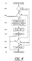
- step 125 a flow chart for a specific subroutine to operate the crankcase heater.
- the crankcase heater, step 125 is shown having substeps 125A through 125G before proceeding to the OFR plus REV valve step 126.
- step 125A questions whether the system is in the force mode. If the system is in the force mode it proceeds to turn the crankcase heater on. If the compressor is not in the force mode the logic proceeds to step 125B to determine whether the compressor is energized. If the compressor is not energized then the logic proceeds to step 125F to determine if the crankcase heater delay is accomplished. If the crankcase heater delay is accomplished then sequential operation turns the crankcase heater on at step 125G. If the crankcase heater delay is not completed sequential operation proceeds to step 126.
- step 125B If the compressor is on as determined by step 125B then a calculation is made to determine a run time value RT. RT is determined by decrementing from five to zero in one unit increments for each one minute interval of continuous operating time of the compressor.
- the step 125C then calculates a crankcase heater delay by multiplying five times the quantity of five minus the run time. This calculation determines the total delay during which it is not necessary to operate the crankcase heater. Hence, if the compressor were run for a total of three minutes then step 125C would calculate the run time as two. Step 125D would then calculate that five times five minus two (or three) equals fifteen. It would be this fifteen minutes that is then utilized as the crankcase heater delay.
- Step 125E indicates that the crankcase heater is de-energized when the compressor is energized. Upon completion of the crankcase heater delay the crankcase heater is turned on at step 125G by step 125F determining the delay is completed.
- crankcase heater is maintained in an energized state at all times except when either the compressor is operating or for a delay period after the compressor has operated, said delay period being calculated to equal five minutes for each one minute of compressor operation time up to a maximum of twenty-five minutes.
- the crankcase heater delay upon termination of compressor operation, is twenty-five minutes.
- crankcase heater relay 52 which controls crankcase heater relay contacts CH R-1 for determining when to energize and de-energize crankcase heater CCH or 35 is controlled via the central processing unit 50 output CH R.
- steps 125E and 125G determine when the crankcase heater should be turned on and off. Since the crankcase heater contacts CH R-1 are normally closed the operative step to de-energize crankcase heater CCH will be the energization of crankcase heater relay CHR.
- the above-described control, wiring schematic and flow charts disclose a method and apparatus for controlling the crankcase heater of a refrigeration system.
- the crankcase heater is maintained energized except during operation of the compressor and except for a certain delay period after compressor operation.
- the delay period is a function of the duration of the compressor operation period and the heat energy stored within the compressor during the period of operation.
Landscapes
- Engineering & Computer Science (AREA)
- Physics & Mathematics (AREA)
- Mechanical Engineering (AREA)
- General Engineering & Computer Science (AREA)
- General Physics & Mathematics (AREA)
- Automation & Control Theory (AREA)
- Thermal Sciences (AREA)
- Air Conditioning Control Device (AREA)
- Control Of Positive-Displacement Pumps (AREA)
- Lubrication Of Internal Combustion Engines (AREA)
- Compressor (AREA)
Claims (13)
Applications Claiming Priority (2)
| Application Number | Priority Date | Filing Date | Title |
|---|---|---|---|
| US06/362,785 US4444017A (en) | 1982-03-29 | 1982-03-29 | Method and apparatus for controlling the operation of a compressor crankcase heater |
| US362785 | 1989-06-07 |
Publications (3)
| Publication Number | Publication Date |
|---|---|
| EP0090760A2 EP0090760A2 (fr) | 1983-10-05 |
| EP0090760A3 EP0090760A3 (en) | 1984-05-09 |
| EP0090760B1 true EP0090760B1 (fr) | 1985-08-14 |
Family
ID=23427518
Family Applications (1)
| Application Number | Title | Priority Date | Filing Date |
|---|---|---|---|
| EP83630041A Expired EP0090760B1 (fr) | 1982-03-29 | 1983-03-04 | Méthode et appareillage pour commander les opérations du réchauffeur de carter d'un compresseur |
Country Status (5)
| Country | Link |
|---|---|
| US (1) | US4444017A (fr) |
| EP (1) | EP0090760B1 (fr) |
| JP (1) | JPH073224B2 (fr) |
| AU (1) | AU544462B2 (fr) |
| DE (1) | DE3360545D1 (fr) |
Cited By (1)
| Publication number | Priority date | Publication date | Assignee | Title |
|---|---|---|---|---|
| DE4205918B4 (de) * | 1991-02-26 | 2005-04-07 | Samsung Electronics Co., Ltd., Suwon | Verfahren zur Steuerung des Kompressors eines zum Kühlen und Heizen verwendbaren Klimagerätes |
Families Citing this family (15)
| Publication number | Priority date | Publication date | Assignee | Title |
|---|---|---|---|---|
| DE3905553A1 (de) * | 1989-02-23 | 1990-08-30 | Metallgesellschaft Ag | Wirbelbrennkammer |
| US6318966B1 (en) | 1999-04-06 | 2001-11-20 | York International Corporation | Method and system for controlling a compressor |
| US6302654B1 (en) * | 2000-02-29 | 2001-10-16 | Copeland Corporation | Compressor with control and protection system |
| WO2009096620A1 (fr) * | 2008-02-01 | 2009-08-06 | Carrier Corporation | Procédé et appareil pour protéger un compresseur de système de climatisation |
| JP5404110B2 (ja) * | 2009-03-12 | 2014-01-29 | 三菱電機株式会社 | 空気調和装置 |
| US8734125B2 (en) | 2009-09-24 | 2014-05-27 | Emerson Climate Technologies, Inc. | Crankcase heater systems and methods for variable speed compressors |
| JP5264871B2 (ja) * | 2010-12-09 | 2013-08-14 | 三菱電機株式会社 | 空気調和機 |
| US9903627B2 (en) | 2012-11-06 | 2018-02-27 | Carrier Corporation | Method of operating an air conditioning system including reducing the energy consumed by the compressor crank case heaters |
| US9181939B2 (en) * | 2012-11-16 | 2015-11-10 | Emerson Climate Technologies, Inc. | Compressor crankcase heating control systems and methods |
| JP5803958B2 (ja) * | 2013-03-08 | 2015-11-04 | ダイキン工業株式会社 | 冷凍装置 |
| EP2984422B1 (fr) * | 2013-04-12 | 2020-10-28 | Emerson Climate Technologies, Inc. | Compresseur à commande de démarrage à l'état noyé |
| JP6440930B2 (ja) * | 2013-06-20 | 2018-12-19 | 三菱重工サーマルシステムズ株式会社 | 空気調和機及び空気調和機の制御方法 |
| US9353738B2 (en) | 2013-09-19 | 2016-05-31 | Emerson Climate Technologies, Inc. | Compressor crankcase heating control systems and methods |
| US9482222B2 (en) | 2013-10-08 | 2016-11-01 | Lennox Industries, Inc. | System for heating a compressor assembly in an HVAC system |
| CN112781274B (zh) * | 2020-12-25 | 2022-02-18 | 珠海格力电器股份有限公司 | 热泵机组控制方法 |
Family Cites Families (8)
| Publication number | Priority date | Publication date | Assignee | Title |
|---|---|---|---|---|
| US3312081A (en) * | 1965-08-03 | 1967-04-04 | Carrier Corp | Control apparatus for refrigeration system |
| US3377816A (en) * | 1966-08-01 | 1968-04-16 | Carrier Corp | Compressor control arrangement |
| US3577741A (en) * | 1969-06-02 | 1971-05-04 | Carrier Corp | Refrigeration apparatus |
| US4066869A (en) * | 1974-12-06 | 1978-01-03 | Carrier Corporation | Compressor lubricating oil heater control |
| GB1587452A (en) * | 1977-07-18 | 1981-04-01 | Electricity Council | Compressors for heat pumps |
| JPS603354Y2 (ja) * | 1977-10-04 | 1985-01-30 | ダイキン工業株式会社 | 冷凍装置 |
| US4236379A (en) * | 1979-01-04 | 1980-12-02 | Honeywell Inc. | Heat pump compressor crankcase low differential temperature detection and control system |
| CA1133097A (fr) * | 1980-04-24 | 1982-10-05 | Maurice Yunik | Temporisateur a commande thermostatique |
-
1982
- 1982-03-29 US US06/362,785 patent/US4444017A/en not_active Expired - Fee Related
-
1983
- 1983-03-04 DE DE8383630041T patent/DE3360545D1/de not_active Expired
- 1983-03-04 EP EP83630041A patent/EP0090760B1/fr not_active Expired
- 1983-03-25 AU AU12880/83A patent/AU544462B2/en not_active Ceased
- 1983-03-29 JP JP58053456A patent/JPH073224B2/ja not_active Expired - Lifetime
Cited By (1)
| Publication number | Priority date | Publication date | Assignee | Title |
|---|---|---|---|---|
| DE4205918B4 (de) * | 1991-02-26 | 2005-04-07 | Samsung Electronics Co., Ltd., Suwon | Verfahren zur Steuerung des Kompressors eines zum Kühlen und Heizen verwendbaren Klimagerätes |
Also Published As
| Publication number | Publication date |
|---|---|
| EP0090760A2 (fr) | 1983-10-05 |
| US4444017A (en) | 1984-04-24 |
| AU544462B2 (en) | 1985-05-30 |
| JPS58206895A (ja) | 1983-12-02 |
| JPH073224B2 (ja) | 1995-01-18 |
| EP0090760A3 (en) | 1984-05-09 |
| DE3360545D1 (en) | 1985-09-19 |
Similar Documents
| Publication | Publication Date | Title |
|---|---|---|
| US4449375A (en) | Method and apparatus for controlling the operation of an indoor fan associated with an air conditioning unit | |
| EP0090760B1 (fr) | Méthode et appareillage pour commander les opérations du réchauffeur de carter d'un compresseur | |
| US4236379A (en) | Heat pump compressor crankcase low differential temperature detection and control system | |
| EP0090759B1 (fr) | Appareillage d'auto-contrôle d'un thermostat | |
| US6792766B2 (en) | Zone demand controlled dual air conditioning system and controller therefor | |
| US9671125B2 (en) | Fan controller | |
| US4470266A (en) | Timer speedup for servicing an air conditioning unit with an electronic control | |
| US4094166A (en) | Air conditioning control system | |
| CA1125888A (fr) | Systeme de commande-regulation sur pompe a chaleur, et de detection du mauvais fonctionnement de ladite pompe | |
| KR900002319B1 (ko) | 냉동시스템의 작동방법과 제어시스템 | |
| US4286438A (en) | Condition responsive liquid line valve for refrigeration appliance | |
| US4228846A (en) | Control apparatus for a two-speed heat pump | |
| US9500386B1 (en) | Fan controller | |
| US5701750A (en) | Zone demand controlled dual heat pump system and controller therefor | |
| CA2161047C (fr) | Climatiseur d'air; mode de fonctionnement | |
| EP0123554A2 (fr) | Unité frigorifique | |
| US4493194A (en) | Apparatus for controlling the operation of an indoor fan associated with an air conditioning unit | |
| US4487031A (en) | Method and apparatus for controlling compressor capacity | |
| US3159981A (en) | Heat pump including frost control means | |
| US4474227A (en) | Gas valve lockout during compressor operation in an air conditioning system | |
| US2590061A (en) | Industrial liquid cooler automatic liquid level control | |
| US4459815A (en) | Air conditioner | |
| US4067383A (en) | Heating and cooling system for a multiple coil installation | |
| US4483388A (en) | Apparatus and method for providing failsafe supplemental heat _regulation in an air conditioning control | |
| US3034314A (en) | Refrigerating apparatus |
Legal Events
| Date | Code | Title | Description |
|---|---|---|---|
| PUAI | Public reference made under article 153(3) epc to a published international application that has entered the european phase |
Free format text: ORIGINAL CODE: 0009012 |
|
| AK | Designated contracting states |
Kind code of ref document: A2 Designated state(s): DE FR GB Designated state(s): DE FR GB |
|
| PUAL | Search report despatched |
Free format text: ORIGINAL CODE: 0009013 |
|
| RHK1 | Main classification (correction) |
Ipc: F25B 31/00 |
|
| AK | Designated contracting states |
Kind code of ref document: A3 Designated state(s): DE FR GB Designated state(s): DE FR GB |
|
| 17P | Request for examination filed |
Effective date: 19840618 |
|
| GRAA | (expected) grant |
Free format text: ORIGINAL CODE: 0009210 |
|
| AK | Designated contracting states |
Kind code of ref document: B1 Designated state(s): DE FR GB Designated state(s): DE FR GB |
|
| REF | Corresponds to: |
Ref document number: 3360545 Country of ref document: DE Date of ref document: 19850919 |
|
| ET | Fr: translation filed | ||
| PLBE | No opposition filed within time limit |
Free format text: ORIGINAL CODE: 0009261 |
|
| STAA | Information on the status of an ep patent application or granted ep patent |
Free format text: STATUS: NO OPPOSITION FILED WITHIN TIME LIMIT |
|
| 26N | No opposition filed | ||
| PGFP | Annual fee paid to national office [announced via postgrant information from national office to epo] |
Ref country code: FR Payment date: 19950208 Year of fee payment: 13 |
|
| PGFP | Annual fee paid to national office [announced via postgrant information from national office to epo] |
Ref country code: GB Payment date: 19950216 Year of fee payment: 13 |
|
| PGFP | Annual fee paid to national office [announced via postgrant information from national office to epo] |
Ref country code: DE Payment date: 19950217 Year of fee payment: 13 |
|
| PG25 | Lapsed in a contracting state [announced via postgrant information from national office to epo] |
Ref country code: GB Effective date: 19960304 |
|
| GBPC | Gb: european patent ceased through non-payment of renewal fee |
Effective date: 19960304 |
|
| PG25 | Lapsed in a contracting state [announced via postgrant information from national office to epo] |
Ref country code: FR Effective date: 19961129 |
|
| PG25 | Lapsed in a contracting state [announced via postgrant information from national office to epo] |
Ref country code: DE Effective date: 19961203 |
|
| REG | Reference to a national code |
Ref country code: FR Ref legal event code: ST |