EP0090794A2 - Bâtiment - Google Patents
Bâtiment Download PDFInfo
- Publication number
- EP0090794A2 EP0090794A2 EP83890043A EP83890043A EP0090794A2 EP 0090794 A2 EP0090794 A2 EP 0090794A2 EP 83890043 A EP83890043 A EP 83890043A EP 83890043 A EP83890043 A EP 83890043A EP 0090794 A2 EP0090794 A2 EP 0090794A2
- Authority
- EP
- European Patent Office
- Prior art keywords
- wall
- ventilation duct
- heat
- building
- wall body
- Prior art date
- Legal status (The legal status is an assumption and is not a legal conclusion. Google has not performed a legal analysis and makes no representation as to the accuracy of the status listed.)
- Granted
Links
Images

Classifications
-
- E—FIXED CONSTRUCTIONS
- E04—BUILDING
- E04B—GENERAL BUILDING CONSTRUCTIONS; WALLS, e.g. PARTITIONS; ROOFS; FLOORS; CEILINGS; INSULATION OR OTHER PROTECTION OF BUILDINGS
- E04B1/00—Constructions in general; Structures which are not restricted either to walls, e.g. partitions, or floors or ceilings or roofs
- E04B1/62—Insulation or other protection; Elements or use of specified material therefor
- E04B1/74—Heat, sound or noise insulation, absorption, or reflection; Other building methods affording favourable thermal or acoustical conditions, e.g. accumulating of heat within walls
- E04B1/76—Heat, sound or noise insulation, absorption, or reflection; Other building methods affording favourable thermal or acoustical conditions, e.g. accumulating of heat within walls specifically with respect to heat only
- E04B1/7608—Heat, sound or noise insulation, absorption, or reflection; Other building methods affording favourable thermal or acoustical conditions, e.g. accumulating of heat within walls specifically with respect to heat only comprising a prefabricated insulating layer, disposed between two other layers or panels
- E04B1/7612—Heat, sound or noise insulation, absorption, or reflection; Other building methods affording favourable thermal or acoustical conditions, e.g. accumulating of heat within walls specifically with respect to heat only comprising a prefabricated insulating layer, disposed between two other layers or panels in combination with an air space
-
- F—MECHANICAL ENGINEERING; LIGHTING; HEATING; WEAPONS; BLASTING
- F24—HEATING; RANGES; VENTILATING
- F24D—DOMESTIC- OR SPACE-HEATING SYSTEMS, e.g. CENTRAL HEATING SYSTEMS; DOMESTIC HOT-WATER SUPPLY SYSTEMS; ELEMENTS OR COMPONENTS THEREFOR
- F24D5/00—Hot-air central heating systems; Exhaust gas central heating systems
- F24D5/005—Hot-air central heating systems; Exhaust gas central heating systems combined with solar energy
Definitions
- the invention relates to a building with an outer wall consisting of a wall body and an outer cladding in front of it at a distance, the space between the wall body and the outer cladding being designed as a vertical ventilation duct.
- either heat transfer to the outside air or heating of the inside of the building by the outside air or solar radiation should usually be prevented in buildings, whereby heat transfer from the inside of the building and in the summer months in particular should be prevented in the summer months .
- the outer walls of the buildings are provided with appropriately dimensioned thermal insulation layers, which not only increase the construction effort, but also cannot always fulfill their task satisfactorily, especially if the interior of the building is to be protected from undesired warming without cooling in warm seasons. This thermal insulation can only hinder heat transfer through the outer wall and not completely exclude it.
- strong heat insulation prevents heat dissipation to the outside, which can be desirable in the warm seasons, especially if a glass house effect is to be expected for large glazed areas.
- the two flow channels are only connected to the interior of the building, it is not possible to prevent heating of the interior of the building due to high outside temperatures with simple means, because the air heated via the outer shell is not directed to the outside but to the inside . Even if the outer flow channel is closed, such a structure will therefore heat up in an undesirable manner, which requires a considerable amount of energy for appropriate cooling. Conversely, if heat is to be released from the inside of the building to the outside air, the unavoidable air flow inside the two flow channels results in an increased heat output, even if the outer channel is closed and the air layer in this channel has an insulating effect.
- the invention is therefore based on the object of adapting the outer wall thermal insulation of a building with simple means to the external conditions with regard to temperature and solar radiation.
- the invention solves the problem in that a control member is provided for optionally opening and shutting off the ventilation duct.
- the control element for the ventilation duct can advantageously be actuated as a function of the shading device, which ensures particularly simple handling.
- the shading device will generally only be used if greater heat radiation is to be expected, which of course ensures that the outer wall is heated accordingly.
- the opening of the ventilation duct which is carried out when the shading device is actuated ensures heat dissipation and thus cooling of the outer wall.
- connection of a shading device with the described rear ventilation of the outer cladding of the outer wall of a building is particularly simple in terms of construction if the control element is placed in the ventilation signal as a shading device for windows or the like. This means that shading and ventilation of an outer wall is inevitable.
- the advantage is achieved that between the shading device and the wall surface to be shaded, a ventilation channel between the outer cladding and the inner wall body is created, so that effective cooling can also be achieved in the area of the shading device in its working position.
- the control element designed as a shading device can have a cover closing the ventilation channel, which is moved when the shading device is used and releases the flow channel.
- the outer wall 1 shown in the drawing of a building consists of an inner wall body 2 and an outer cladding 3 which is spaced upstream of this wall body 2 and which, according to FIG. 1, consists of mutually offset wall panels and according to FIG Plastic or metal.
- this outer cladding can also be designed completely differently, since it is only important in the context of the invention that the space between the inner wall body 2 and the outer cladding forms a vertical ventilation duct 4.
- This ventilation duct 4 which results between the outer cladding 3 and a heat-insulating layer 5 on the outside of the wall body 2, is closed at the top by a control element 6, which controls the air flow within the ventilation duct 4.
- the shading device 7 consists of a venetian blind, the slats 10 of which are guided on both sides in vertical rails 11 and can be pulled in front of the window 8 with an actuating device, which is indicated by the arrows 12 in FIG. 1.
- the ventilation duct 4 is closed with the help of the control element 6.
- the air cushion enclosed in the ventilation duct 4 acts as additional heat insulation, so that the desired insulation values can also be ensured with regard to heat transfer from the inside to the outside, without having to form the heat-insulating layer 5 particularly strongly.
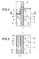
- the control member 6 for the ventilation channel 4 is not formed by a shading device provided with a cover, but by a slide 14 which is slidably mounted transversely to the ventilation channel 4 in a housing 15 which is spaced apart in the direction of displacement of the slide 14 has provided through openings 16 which correspond to corresponding through openings 17 of the slide 14.
- the through openings 16 of the housing 15 closing the ventilation duct 4 can consequently be closed or opened in order to block or open the ventilation duct 4 for an air flow.
- this slide 14 need not be arranged in the parapet area of a window 8, as is shown in FIGS. 4 and 5.
- the slider will preferably be attached to the upper end of the outer wall. What is important is not the position of the control element 6, but the controllability of the air flow within the ventilation duct 4 that results between the outer cladding 3 and the inner wall body 2.
Landscapes
- Engineering & Computer Science (AREA)
- Physics & Mathematics (AREA)
- Architecture (AREA)
- Sustainable Development (AREA)
- Thermal Sciences (AREA)
- Civil Engineering (AREA)
- Structural Engineering (AREA)
- Life Sciences & Earth Sciences (AREA)
- Acoustics & Sound (AREA)
- Sustainable Energy (AREA)
- Electromagnetism (AREA)
- Chemical & Material Sciences (AREA)
- Combustion & Propulsion (AREA)
- Mechanical Engineering (AREA)
- General Engineering & Computer Science (AREA)
- Building Environments (AREA)
- Duct Arrangements (AREA)
- Specific Sealing Or Ventilating Devices For Doors And Windows (AREA)
Applications Claiming Priority (2)
| Application Number | Priority Date | Filing Date | Title |
|---|---|---|---|
| AT0123382A AT374227B (de) | 1982-03-30 | 1982-03-30 | Bauwerk |
| AT1233/82 | 1982-03-30 |
Publications (3)
| Publication Number | Publication Date |
|---|---|
| EP0090794A2 true EP0090794A2 (fr) | 1983-10-05 |
| EP0090794A3 EP0090794A3 (en) | 1984-07-04 |
| EP0090794B1 EP0090794B1 (fr) | 1987-09-16 |
Family
ID=3509480
Family Applications (1)
| Application Number | Title | Priority Date | Filing Date |
|---|---|---|---|
| EP19830890043 Expired EP0090794B1 (fr) | 1982-03-30 | 1983-03-24 | Bâtiment |
Country Status (3)
| Country | Link |
|---|---|
| EP (1) | EP0090794B1 (fr) |
| AT (1) | AT374227B (fr) |
| DE (1) | DE3373689D1 (fr) |
Cited By (3)
| Publication number | Priority date | Publication date | Assignee | Title |
|---|---|---|---|---|
| DE4042387A1 (de) * | 1990-10-13 | 1992-04-16 | Alco Systeme Gmbh | Bauwerk |
| EP0467876A3 (en) * | 1990-07-14 | 1992-07-29 | Rls-Bautechnologie Ag | High-rise building |
| EP0481217A3 (en) * | 1990-10-13 | 1992-09-02 | Alco-Systeme Gmbh | Building |
Families Citing this family (3)
| Publication number | Priority date | Publication date | Assignee | Title |
|---|---|---|---|---|
| CH674391A5 (fr) * | 1986-12-23 | 1990-05-31 | Sarna Granol Ag | |
| AT403073B (de) * | 1987-06-04 | 1997-11-25 | Jordan Paul Dipl Ing | Verfahren und hochhaus zur verbesserung der aussenluft, insbesondere stadtluft |
| AT410456B9 (de) * | 2000-12-12 | 2003-12-29 | Consultplan Tech Buero Ges M B | Hochbau mit einer vielzahl von geschossen sowie profil mit metall |
Family Cites Families (8)
| Publication number | Priority date | Publication date | Assignee | Title |
|---|---|---|---|---|
| CH64648A (de) * | 1913-01-16 | 1914-04-16 | Reinh Rosenthal Nicolai | Einrichtung zur Vermeidung des Temperaturausgleiches zwischen dem Innern von Gebäuden, Fahrzeugen etc. und der Außenluft |
| FR1036846A (fr) * | 1951-05-08 | 1953-09-11 | Revêtement écran pour parois de construction telles que murs ou toitures | |
| AT236607B (de) * | 1959-02-11 | 1964-11-10 | Gertraude Oehler | Außenwandverkleidung in Form einer bleibenden Schalung |
| AT351716B (de) * | 1974-05-31 | 1979-08-10 | Linecker Josef | Gebaeude, insbesondere halle |
| AT344380B (de) * | 1975-08-19 | 1978-07-25 | Winkler Hans H Dipl Ing Dkfm | Zweischaliges, hinterlueftetes mauerwerk |
| AT350237B (de) * | 1976-08-20 | 1979-05-25 | Leitl Werke Bauhuette | Fassadenkonstruktion aus plattenfoermigen, vor- zugsweise keramischen bauelementen |
| DE3026635A1 (de) * | 1978-02-27 | 1982-02-11 | Schmidt Reuter Ingenieurgesellschaft mbH & Co KG, 5000 Köln | Luftfuehrende fassade |
| US4286420A (en) * | 1979-04-18 | 1981-09-01 | Pharmakidis Panayiotis D | Heat retention wall system |
-
1982
- 1982-03-30 AT AT0123382A patent/AT374227B/de not_active IP Right Cessation
-
1983
- 1983-03-24 EP EP19830890043 patent/EP0090794B1/fr not_active Expired
- 1983-03-24 DE DE8383890043T patent/DE3373689D1/de not_active Expired
Cited By (5)
| Publication number | Priority date | Publication date | Assignee | Title |
|---|---|---|---|---|
| EP0467876A3 (en) * | 1990-07-14 | 1992-07-29 | Rls-Bautechnologie Ag | High-rise building |
| US5347779A (en) * | 1990-07-14 | 1994-09-20 | Rls-Bautechnologie-Ag | High-rise building |
| TR26161A (tr) * | 1990-07-14 | 1995-02-15 | Paul Jordan Dipl Ing | BIR BINA DIS DUVARI ILE BIR BINA KILIFINDAN OLUSAN YüKSEK BINA |
| DE4042387A1 (de) * | 1990-10-13 | 1992-04-16 | Alco Systeme Gmbh | Bauwerk |
| EP0481217A3 (en) * | 1990-10-13 | 1992-09-02 | Alco-Systeme Gmbh | Building |
Also Published As
| Publication number | Publication date |
|---|---|
| ATA123382A (de) | 1983-08-15 |
| AT374227B (de) | 1984-03-26 |
| EP0090794A3 (en) | 1984-07-04 |
| EP0090794B1 (fr) | 1987-09-16 |
| DE3373689D1 (en) | 1987-10-22 |
Similar Documents
| Publication | Publication Date | Title |
|---|---|---|
| DE3216581C2 (de) | Schall- und wärmeisolierendes Verbundfenster mit Schalldämmlüftung | |
| DE4424524C2 (de) | Fassadenkonstruktion in zweischaliger Bauweise | |
| EP0090794A2 (fr) | Bâtiment | |
| EP2492432B1 (fr) | Caisson de store ou de store à lamelles ainsi qu'insert d'isolation thermique associé | |
| DE3233499A1 (de) | Solarpaneele insbesondere fuer aussenfenster | |
| EP0256441B1 (fr) | Elément de construction vitré | |
| DE3928259A1 (de) | Luftfuehrendes fensterelement | |
| DE4431928A1 (de) | Wärmedämmendes Fenster | |
| DE10033535A1 (de) | Doppelfassade | |
| DE2744451A1 (de) | Verschlusseinrichtung fuer fenster, tueren o.dgl. oeffnungen | |
| DE69011121T2 (de) | Element zur Lüftung von Gebäuden wie Wintergärden, Solaria und Gewächshäusern. | |
| DE3627096A1 (de) | Verglastes bauelement, insbesondere tuer, mit einer umkehrbaren glasscheibenanordnung | |
| DE3227721C2 (de) | Rolladen oder schiebbarer Laden für Wandöffnungen an Gebäuden | |
| DE2420548A1 (de) | Brandwand-abschluss in form von feuerschutzelementen | |
| EP0663573A2 (fr) | Façade à double paroi | |
| DE202016008921U1 (de) | Fensterdämmelement | |
| DE3013440A1 (de) | Fenster oder tuer mit integrierter lueftungsvorrichtung | |
| EP0005259B1 (fr) | Système de climatisation d'un local fermé | |
| EP0481217B1 (fr) | Bâtiment | |
| DE3422439C2 (de) | Fenster mit in eine Bauwerkswand einzubauendem Fensterrahmen und darin angeordnetem Flügelrahmen | |
| DE8327232U1 (de) | Jalousie zum abdecken einer wandoeffnung | |
| DE2842476C2 (de) | Innenschattierung für Gewächshäuser | |
| DE19818380B4 (de) | Doppelfenster | |
| DE3347583A1 (de) | Feuerbestaendige fensterwand | |
| DE8309181U1 (de) | Fenster- und/oder rolladenkasten-element |
Legal Events
| Date | Code | Title | Description |
|---|---|---|---|
| PUAI | Public reference made under article 153(3) epc to a published international application that has entered the european phase |
Free format text: ORIGINAL CODE: 0009012 |
|
| AK | Designated contracting states |
Kind code of ref document: A2 Designated state(s): BE CH DE FR GB IT LI LU NL SE Designated state(s): BE CH DE FR GB IT LI LU NL SE |
|
| PUAL | Search report despatched |
Free format text: ORIGINAL CODE: 0009013 |
|
| AK | Designated contracting states |
Kind code of ref document: A3 Designated state(s): BE CH DE FR GB IT LI LU NL SE Designated state(s): BE CH DE FR GB IT LI LU NL SE |
|
| 17P | Request for examination filed |
Effective date: 19841205 |
|
| GRAA | (expected) grant |
Free format text: ORIGINAL CODE: 0009210 |
|
| AK | Designated contracting states |
Kind code of ref document: B1 Designated state(s): BE CH DE FR GB IT LI LU NL SE |
|
| REF | Corresponds to: |
Ref document number: 3373689 Country of ref document: DE Date of ref document: 19871022 |
|
| ET | Fr: translation filed | ||
| GBT | Gb: translation of ep patent filed (gb section 77(6)(a)/1977) | ||
| ITF | It: translation for a ep patent filed | ||
| PLBE | No opposition filed within time limit |
Free format text: ORIGINAL CODE: 0009261 |
|
| STAA | Information on the status of an ep patent application or granted ep patent |
Free format text: STATUS: NO OPPOSITION FILED WITHIN TIME LIMIT |
|
| 26N | No opposition filed | ||
| ITTA | It: last paid annual fee | ||
| EPTA | Lu: last paid annual fee | ||
| EAL | Se: european patent in force in sweden |
Ref document number: 83890043.9 |
|
| PGFP | Annual fee paid to national office [announced via postgrant information from national office to epo] |
Ref country code: LU Payment date: 19960301 Year of fee payment: 14 |
|
| PGFP | Annual fee paid to national office [announced via postgrant information from national office to epo] |
Ref country code: SE Payment date: 19960326 Year of fee payment: 14 |
|
| PGFP | Annual fee paid to national office [announced via postgrant information from national office to epo] |
Ref country code: NL Payment date: 19960329 Year of fee payment: 14 |
|
| PGFP | Annual fee paid to national office [announced via postgrant information from national office to epo] |
Ref country code: CH Payment date: 19960401 Year of fee payment: 14 |
|
| PGFP | Annual fee paid to national office [announced via postgrant information from national office to epo] |
Ref country code: BE Payment date: 19960412 Year of fee payment: 14 |
|
| PG25 | Lapsed in a contracting state [announced via postgrant information from national office to epo] |
Ref country code: LU Free format text: LAPSE BECAUSE OF NON-PAYMENT OF DUE FEES Effective date: 19970324 |
|
| PG25 | Lapsed in a contracting state [announced via postgrant information from national office to epo] |
Ref country code: SE Effective date: 19970325 |
|
| PGFP | Annual fee paid to national office [announced via postgrant information from national office to epo] |
Ref country code: FR Payment date: 19970328 Year of fee payment: 15 |
|
| PG25 | Lapsed in a contracting state [announced via postgrant information from national office to epo] |
Ref country code: LI Effective date: 19970331 Ref country code: CH Effective date: 19970331 Ref country code: BE Effective date: 19970331 |
|
| PGFP | Annual fee paid to national office [announced via postgrant information from national office to epo] |
Ref country code: GB Payment date: 19970401 Year of fee payment: 15 |
|
| BERE | Be: lapsed |
Owner name: JORDAN PAUL DIPL.-ING. Effective date: 19970331 |
|
| PG25 | Lapsed in a contracting state [announced via postgrant information from national office to epo] |
Ref country code: NL Effective date: 19971001 |
|
| REG | Reference to a national code |
Ref country code: CH Ref legal event code: PL |
|
| NLV4 | Nl: lapsed or anulled due to non-payment of the annual fee |
Effective date: 19971001 |
|
| EUG | Se: european patent has lapsed |
Ref document number: 83890043.9 |
|
| PG25 | Lapsed in a contracting state [announced via postgrant information from national office to epo] |
Ref country code: GB Free format text: LAPSE BECAUSE OF NON-PAYMENT OF DUE FEES Effective date: 19980324 |
|
| PG25 | Lapsed in a contracting state [announced via postgrant information from national office to epo] |
Ref country code: FR Free format text: THE PATENT HAS BEEN ANNULLED BY A DECISION OF A NATIONAL AUTHORITY Effective date: 19980331 |
|
| GBPC | Gb: european patent ceased through non-payment of renewal fee |
Effective date: 19980324 |
|
| REG | Reference to a national code |
Ref country code: FR Ref legal event code: ST |
|
| PGFP | Annual fee paid to national office [announced via postgrant information from national office to epo] |
Ref country code: DE Payment date: 20020320 Year of fee payment: 20 |