EP0090796B1 - Dispositif de réglage du début de refoulement d'une pompe d'injection de combustible - Google Patents
Dispositif de réglage du début de refoulement d'une pompe d'injection de combustible Download PDFInfo
- Publication number
- EP0090796B1 EP0090796B1 EP19830890049 EP83890049A EP0090796B1 EP 0090796 B1 EP0090796 B1 EP 0090796B1 EP 19830890049 EP19830890049 EP 19830890049 EP 83890049 A EP83890049 A EP 83890049A EP 0090796 B1 EP0090796 B1 EP 0090796B1
- Authority
- EP
- European Patent Office
- Prior art keywords
- injection pump
- fuel injection
- electric motor
- gear
- internal
- Prior art date
- Legal status (The legal status is an assumption and is not a legal conclusion. Google has not performed a legal analysis and makes no representation as to the accuracy of the status listed.)
- Expired
Links
- 238000002347 injection Methods 0.000 title claims description 56
- 239000007924 injection Substances 0.000 title claims description 56
- 239000000446 fuel Substances 0.000 title claims description 24
- 238000002485 combustion reaction Methods 0.000 claims description 15
- 230000005540 biological transmission Effects 0.000 claims description 8
- 230000007246 mechanism Effects 0.000 claims description 3
- 230000001105 regulatory effect Effects 0.000 claims 6
- 230000001276 controlling effect Effects 0.000 claims 1
- 238000012432 intermediate storage Methods 0.000 claims 1
- 238000006073 displacement reaction Methods 0.000 description 6
- 230000002349 favourable effect Effects 0.000 description 5
- 230000033001 locomotion Effects 0.000 description 5
- 238000000034 method Methods 0.000 description 4
- 230000008569 process Effects 0.000 description 4
- 238000010586 diagram Methods 0.000 description 3
- 230000006870 function Effects 0.000 description 3
- 239000007921 spray Substances 0.000 description 3
- 230000008901 benefit Effects 0.000 description 2
- 238000006243 chemical reaction Methods 0.000 description 2
- 230000004913 activation Effects 0.000 description 1
- 230000033228 biological regulation Effects 0.000 description 1
- 230000000903 blocking effect Effects 0.000 description 1
- 230000008859 change Effects 0.000 description 1
- 230000006835 compression Effects 0.000 description 1
- 238000007906 compression Methods 0.000 description 1
- 230000000694 effects Effects 0.000 description 1
- 239000003344 environmental pollutant Substances 0.000 description 1
- 230000017525 heat dissipation Effects 0.000 description 1
- 239000010687 lubricating oil Substances 0.000 description 1
- 239000003921 oil Substances 0.000 description 1
- 231100000719 pollutant Toxicity 0.000 description 1
- 230000036316 preload Effects 0.000 description 1
- 238000005086 pumping Methods 0.000 description 1
- 238000007789 sealing Methods 0.000 description 1
- 239000000243 solution Substances 0.000 description 1
Images

Classifications
-
- F—MECHANICAL ENGINEERING; LIGHTING; HEATING; WEAPONS; BLASTING
- F02—COMBUSTION ENGINES; HOT-GAS OR COMBUSTION-PRODUCT ENGINE PLANTS
- F02D—CONTROLLING COMBUSTION ENGINES
- F02D1/00—Controlling fuel-injection pumps, e.g. of high pressure injection type
- F02D1/16—Adjustment of injection timing
- F02D1/18—Adjustment of injection timing with non-mechanical means for transmitting control impulse; with amplification of control impulse
-
- F—MECHANICAL ENGINEERING; LIGHTING; HEATING; WEAPONS; BLASTING
- F02—COMBUSTION ENGINES; HOT-GAS OR COMBUSTION-PRODUCT ENGINE PLANTS
- F02D—CONTROLLING COMBUSTION ENGINES
- F02D1/00—Controlling fuel-injection pumps, e.g. of high pressure injection type
- F02D1/16—Adjustment of injection timing
Definitions
- the invention relates to a device for adjusting the start of delivery of a fuel injection pump for injection internal combustion engines, in which in a fixed housing the injection pump shaft is coupled to a drive shaft by means of a sleeve which is axially displaceable by an actuator and has internal gears which engage in external gears of the two coaxially arranged shafts, of which At least one pair of mutually engaging gears runs obliquely to the axis, the sleeve being rotatably supported against axial displacement by a holding element, and the actuator engaging the holding element and being electrically operable as a function of operating variables and being formed by an electric motor.
- the actuator As a centrifugal speed sensor which is seated on the drive shaft driven by the internal combustion engine or on the injection pump shaft, the pivotable centrifugal weights of which, depending on the speed, directly cause the axial displacement of the sleeve.
- a predetermined setting of the start of delivery of the injection pump is thus assigned to each speed of the internal combustion engine.
- AT-B-298 881 the starting position of the sleeve is arbitrarily axially adjustable, as a result of which the control range can be shifted, for example, to adapt the internal combustion engine to different fuels.
- the relative angular position of the drive shaft and the injection pump shaft should be changed automatically as a function of various operating variables without external intervention, in order to change the start of delivery of the injection pump or the start of injection at the injection nozzle in relation to a typical crankshaft position of the internal combustion engine.
- the determination of the favorable start of funding takes place from the point of view of minimizing the specific fuel consumption and the pollutant emission depending on, in particular, the speed and the torque of the internal combustion engine as well as on further characteristic values, such as atmospheric air pressure, intake manifold pressure, engine temperature etc.
- US-A-2 810 275 shows and describes a drive device, a sleeve carrier being arranged between a worm wheel and a sleeve.
- the sleeve carrier has an external thread and is screwed into an internal thread of the stationary housing.
- the required drive torque for the pump which has to be transmitted via the axially displaceable sleeve of the adjusting device, is not of a uniform size, but rather reaches a high peak value at the moment of the pumping process of a pump element of the usually multi-cylinder in-line pump. which extends over a few degrees and then over a certain angle, which is usually larger than the conveying angle, has a value close to zero and can also be slightly negative.
- a distinction is made in the course of the torque over the cam angle of the injection pump shaft, a delivery phase with high torque and a free phase with low torque.
- the invention aims to provide a device for adjusting the start of delivery of a fuel injection pump, the actuator of which manages without excessive power consumption and in which undesired adjustments by the reaction forces of the fuel injection pump are largely avoided.
- the invention essentially consists in a device of the type mentioned at the outset that the holding element is designed as a sleeve carrier arranged coaxially with the sleeve is that the sleeve carrier has an external thread and can be screwed into an internal thread of the fixed housing and the actuator acts on the sleeve carrier to rotate the same and that in the power transmission path from the electric motor to the sleeve carrier a spring loaded in both directions of rotation is provided.
- the invention essentially consists in that the holding element is designed as a sleeve carrier arranged coaxially with the sleeve that the sleeve carrier has an external thread and can be screwed into an internal thread of the fixed housing and the actuator engages the sleeve carrier to rotate the same and that a transducer, such as, for. B.
- a freely programmable Switchgear which is connected to the electric motor for control as a function of the operating variables, or is connected to a buffer for the manipulated variable and only enables the output or transmission of a manipulated variable to be transmitted to the electric motor in the free phase.
- one and the same adjustment device can be adapted to different internal combustion engines and application purposes and numerous influencing variables can be taken into account in cooperation with a specific internal combustion engine.
- the electric motor is expediently a direct current servomotor or a stepper motor.
- a DC servomotor offers the advantage of a favorable ratio of output power to volume, however a position transmitter is required for the momentary system of the sleeve carrier.
- Such a feedback of a signal via the torque system of the sleeve carrier is superfluous when using a stepper motor, but this simplification in terms of circuitry can only be exploited if the torque of the stepper motor, which is lower than that of a DC servomotor, can be found.
- At least one countershaft carrying two gearwheels can be arranged between the electric motor and the sleeve carrier, one of which meshes with an output gear of the electric motor and the other meshes with an external toothing of the sleeve carrier.
- the distance between the shaft of the electric motor and the axis of the sleeve carrier can be bridged with smaller gear wheels and a multi-stage gear ratio can be provided.
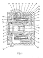
- FIG. 1 shows an embodiment of an adjusting device with a laterally flanged servomotor, the servomotor axis perpendicularly crossing the injection pump axis and the rotary movement being transmitted to the sleeve carrier via a worm gear;
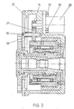
- Fig. 2 shows a second Embodiment with parallel axes of the servomotor and the injection pump, the power being transmitted via spur gears;
- FIG. 3 shows a combination of two gear wheels with built-in spring accumulator, which combination can take the place of the intermediate gear wheel in the embodiment according to FIG. 2, in axial section; 4 shows a view of the combination according to FIG. 3 in the intermediate plane of the two gear wheels and
- FIG. 5 shows a block diagram for the control of the electric motor of the adjusting device in the free phase of the fuel injection pump.
- the adjusting device shown in FIG. 1 interacts with a drive stub 1 of the injection pump shaft of a fuel injection pump for a diesel engine, which is not shown.
- a hub 3 is secured against rotation by means of a disc spring 2 by means of a tubular nut 4.
- a driver 5 is rotatably mounted on the hub 3, axial forces being absorbed by sliding disks 6 and 7, which also allow play adjustment during assembly.
- the driver 5 has a flange-like end region, which is used for connection to a drive shaft driven by the diesel engine.
- a cover 8 covers the interior of the driver 5.
- the connection between the hub 3 and the driver 5 is made by a sleeve 9 with two internal teeth 10 and 11, of which at least one is helical in the manner of a steep thread.
- Corresponding external teeth 12 and 13 on the hub 3 and on the driver 5 are in constant engagement with the associated internal teeth of the sleeve 9.
- two roller bearings 16 and 17 are fastened by means of a nut 14 and a sleeve 15, which are also clamped in a sleeve carrier 18 by means of a nut 19 and a sleeve 20.
- the sleeve carrier 18 has a thread 21 on the outside and a toothing 22.
- the thread 21 is a single-thread or multi-thread motion thread, which is usually designed to be self-locking and is in engagement with a thread 23 in a pot 24.
- the pot 24 is fastened in the housing 25 by means of screws 26, which at the same time serve to fasten the housing 25 to the housing of the injection pump, not shown. It is of course possible to provide the thread 23 directly in the housing 25 and thus to dispense with the pot 24 as a thread carrier.
- the toothing 22 on the sleeve carrier is in engagement with the toothing 27 of a worm wheel 28, which is fastened on the shaft of a stepper motor 29 shown in the contour and converts the rotary movement of the stepper motor shaft into a corresponding rotational movement of the sleeve carrier 18, as a result of which a thread 21 is used simultaneous axial displacement of sleeve carrier 18 and sleeve 9 takes place, which causes the mutual relative adjustment of hub 3 and driver 5.
- Sealing rings 30 and 31 provide a tight seal of the housing 25 closed with a cover 32, which is either filled with oil or connected to the lubricating oil circuit of the diesel engine.
- the thread 21/23 is expediently used as a movement thread, e.g. B. as a trapezoidal thread, and carried out with such a pitch that it is self-locking, so that it exerts no torque on the toothing 22 at thrust forces acting on the sleeve carrier 18 via the two roller bearings 16, 17, but locks itself.
- the toothing 11, 13 and the toothing 10, 12 can also be designed to be self-locking, so that no thrust is released on the sleeve 9 when torque is passed through.
- the thread 21, 23 can be designed with a larger pitch, so it no longer has to have self-locking.
- the advantage of the self-locking design of the toothing and / or the thread is that the servomotor is not loaded by the large torque at the moment of the injection, but on the other hand can perform an unimpeded adjustment in the free phases between the injections. This enables a very small and space-saving design of the servomotor.
- Fig. 2 shows an embodiment of the spray adjuster, in which the servo motor 29 is screwed onto the front of the housing 25 with screws 33 and via a pinion 34 and a bearing 36 mounted on a shaft 35 with a sleeve 36 Gear 37 rotates the sleeve carrier 18 and thus displaces it relative to the housing 25.
- This design is favorable if a lateral flanging of the servomotor 29 according to FIG. 1 is not desired.
- the housing 25 is closed with the cover 32.
- gearwheels with larger diameters or corresponding ratios makes it possible to dispense with gearwheel 37 as an intermediate gearwheel.
- the intermediate gear 37 shows an embodiment of the intermediate gear 37 as a step memory for the embodiment of the adjusting device according to FIG. 2.
- the intermediate gear is here in two parts and consists of the gears 38 and 39, which are braced against each other and only rotate against each other when a predetermined torque is exceeded.
- these two gears can be used as an angular step memory and it is possible to save one or more rotary steps of the stepping motor if the thread or the toothing should be locked during the conveying phase.
- the stepper motor is thus not hindered in its rotation and adjustment and can store the steps to be carried out in the step memory, from which they are made up during the free phase. This makes it possible to carry out a particularly small and space-saving design of the stepping motor without reducing the accuracy of the adjustment.
- FIG. 3 can be used as a countershaft between the stepper motor 29 and the sleeve carrier 18, the pinion 34 of the stepper motor 29 meshing with the smaller gear 38 and the larger gear 39 with the toothing 22 of the sleeve carrier 18.
- Such a rotation angle memory can also be installed in the drive shaft of the worm wheel according to FIG. 1.
- 3 and 4 consists of the two gear wheels 38 and 39, which have prestressed compression springs 41 inserted in groove-shaped corresponding recesses 40 in their side wall. When a predetermined torque occurs, the two gear wheels 38, 39 rotate against each other and return to their starting position when the torque is removed.
- the worm gear of Fig. 1 can also be designed as a helical gear. It is also possible to provide the self-locking neither in the toothing 11/13 nor in the toothing 10/12 nor in the thread 21/23, but only in the worm gear 22/27. Finally, it is possible to do without self-locking in one or more parts of the transmission and to execute the servomotor so vigorously that it can support the torque during the conveying phase or that it can even be adjusted against this torque.
- FIG. 5 shows a block diagram for the control of the electric motor 29 of the adjusting device 42 in the free phase of the fuel injection pump 43 of an internal combustion engine 44.
- a microprocessor 45 is provided, the various factors such as accelerator pedal position, speed, torque, engine temperature, air temperature, air pressure and. Like., Representative electrical signals are supplied via lines 46.
- control values for the start of delivery and the delivery rate of the injection pump 43 are calculated on the basis of predetermined and stored characteristic maps.
- the control signal for the start of delivery reaches a temporary store 48 via a line 47 and from there to the servomotor 29 via a line 49.
- the rotary position sensor 50 for sensing the position of the injection pump shaft 51 is connected via a line 52 to a control input of the temporary store 48 and effects it that signals supplied by the microprocessor 45 via the line 47 during the delivery phase of the injection pump 43 are temporarily stored in the intermediate memory 48 and are only forwarded to the servomotor 29 via the line 49 in the free phase of the injection pump 43.
- This configuration is particularly expedient if the servomotor 29 is a stepper motor which, if activated, would be blocked during the delivery phase of the injection pump 43, as a result of which the relationship between the setpoint value and the actual value would be lost.
- the stepper motor can have a position transmitter and a revolution counter, which components are to be connected to the microprocessor 45 via a line 53 indicated by a broken line, by which measure it can be achieved in a particularly simple manner that the adjusting device for the next starting process after the internal combustion engine 44 has been switched off is brought into a defined starting position.
- the feedback via the line 53 would not be necessary in the case of a stepper motor, or the buffer memory 48 could be omitted if such a feedback was present. In any case, however, the return via line 53 is required if the servomotor 29 is a DC servomotor.
- Whether measures should be taken with a DC servomotor that the servomotor can only be activated in the free phase of the injection pump depends on the power or torque of the motor and also on the heat dissipation possibility of its rotor, since it must be taken into account that in the case of an engine without preventing its activation during the delivery phase of the injection pump, the case may occur that the electric motor in braked state is under power. In the case of rapidly responding disc rotor or bell-armature motors with a low moment of inertia, it seems advisable to control the motor as well as a stepper motor only in the free phase of the injection pump.
Landscapes
- Engineering & Computer Science (AREA)
- Chemical & Material Sciences (AREA)
- Combustion & Propulsion (AREA)
- Mechanical Engineering (AREA)
- General Engineering & Computer Science (AREA)
- High-Pressure Fuel Injection Pump Control (AREA)
- Fuel-Injection Apparatus (AREA)
Claims (3)
Applications Claiming Priority (2)
| Application Number | Priority Date | Filing Date | Title |
|---|---|---|---|
| AT1256/82 | 1982-03-30 | ||
| AT125682 | 1982-03-30 |
Publications (2)
| Publication Number | Publication Date |
|---|---|
| EP0090796A1 EP0090796A1 (fr) | 1983-10-05 |
| EP0090796B1 true EP0090796B1 (fr) | 1986-10-15 |
Family
ID=3509955
Family Applications (1)
| Application Number | Title | Priority Date | Filing Date |
|---|---|---|---|
| EP19830890049 Expired EP0090796B1 (fr) | 1982-03-30 | 1983-03-29 | Dispositif de réglage du début de refoulement d'une pompe d'injection de combustible |
Country Status (2)
| Country | Link |
|---|---|
| EP (1) | EP0090796B1 (fr) |
| DE (1) | DE3366993D1 (fr) |
Families Citing this family (2)
| Publication number | Priority date | Publication date | Assignee | Title |
|---|---|---|---|---|
| AT392120B (de) * | 1983-01-24 | 1991-01-25 | Bosch Robert Ag | Einrichtung zur verstellung des foerderbeginnes einer brennstoffeinspritzpumpe |
| FR2714430B1 (fr) * | 1993-12-27 | 1996-02-09 | Giat Ind Sa | Mécanisme de transmission de couple à commande mécanique et arme comportant un tel mécanisme. |
Family Cites Families (4)
| Publication number | Priority date | Publication date | Assignee | Title |
|---|---|---|---|---|
| NL47716C (fr) * | ||||
| US2810275A (en) * | 1956-12-10 | 1957-10-22 | Angelus Sanitary Can Machine C | Shaft timing adjustment device |
| JPS5339528B1 (fr) * | 1971-03-06 | 1978-10-21 | ||
| US4142498A (en) * | 1977-01-17 | 1979-03-06 | Caterpillar Tractor Co. | Fuel injection pump timing mechanism |
-
1983
- 1983-03-29 EP EP19830890049 patent/EP0090796B1/fr not_active Expired
- 1983-03-29 DE DE8383890049T patent/DE3366993D1/de not_active Expired
Also Published As
| Publication number | Publication date |
|---|---|
| DE3366993D1 (en) | 1986-11-20 |
| EP0090796A1 (fr) | 1983-10-05 |
Similar Documents
| Publication | Publication Date | Title |
|---|---|---|
| DE3590194C2 (de) | Brennstoff-Einspritzpumpe | |
| DE10116707B4 (de) | Vorrichtung zur Relativverdrehung einer Nockenwelle gegenüber einer Kurbelwelle einer Brennkraftmaschine | |
| DE3619956C2 (fr) | ||
| DE69312060T2 (de) | Verstellbare ventilsteuerungseinrichtung | |
| EP0560201B1 (fr) | Pompe à huile pour une scie à chaîne | |
| DE3333931C2 (fr) | ||
| DE3400313C2 (de) | Vorrichtung zur Rezirkulationsregelung der Auspuffgase eines Dieselmotors | |
| DE3010839A1 (de) | Kraftstoffeinspritzpumpe | |
| EP0090796B1 (fr) | Dispositif de réglage du début de refoulement d'une pompe d'injection de combustible | |
| DE2221212A1 (de) | Verfahren und Vorrichtung zum Freihalten des Abgasstromes eines Innenverbrennungsmotors von schaedlichen Gasen | |
| DE2803323C2 (de) | Mechanische, drehzahlabhängige Regelung einer Brennstoff-Einspritzpumpe für eine Brennkraftmaschine | |
| DE3644147A1 (de) | Kraftstoffeinspritzpumpe fuer brennkraftmaschinen | |
| DE3101266C2 (de) | Regeleinrichtung für eine Verteiler-Treibstoffeinspritzpumpe einer Brennkraftmaschine | |
| EP0009475B1 (fr) | Dispositif de réglage pour des moteurs Diesel | |
| DE3245853C2 (fr) | ||
| EP0911492B1 (fr) | Dispositif pour modifier la phase angulaire d'un arbre à cames de moteur à combustion interne | |
| WO1991002897A1 (fr) | Pompe d'injection de carburant pour moteurs a combustion interne | |
| DE2446903A1 (de) | Treibstoffeinspritzpumpe | |
| DE4130125C2 (de) | Mechanische Handverstelleinrichtung für den Regelhub eines Stellgliedes | |
| EP0288669B1 (fr) | Pompe à injection de combustible pour moteur diesel | |
| DE3241572A1 (de) | Brennstoffeinspritzvorrichtung | |
| DE1094040B (de) | Einrichtung zur AEnderung der Ventilsteuerzeiten von Brennkraftmaschinen | |
| DE2131283C3 (de) | Drehzahlregler für Brennkraftmaschinen | |
| AT392120B (de) | Einrichtung zur verstellung des foerderbeginnes einer brennstoffeinspritzpumpe | |
| DE3126002A1 (de) | Kraftstoffeinspritzvorrichtung |
Legal Events
| Date | Code | Title | Description |
|---|---|---|---|
| PUAI | Public reference made under article 153(3) epc to a published international application that has entered the european phase |
Free format text: ORIGINAL CODE: 0009012 |
|
| AK | Designated contracting states |
Kind code of ref document: A1 Designated state(s): DE FR GB Designated state(s): DE FR GB |
|
| 17P | Request for examination filed |
Effective date: 19840306 |
|
| GRAA | (expected) grant |
Free format text: ORIGINAL CODE: 0009210 |
|
| AK | Designated contracting states |
Kind code of ref document: B1 Designated state(s): DE FR GB |
|
| PG25 | Lapsed in a contracting state [announced via postgrant information from national office to epo] |
Ref country code: FR Free format text: THE PATENT HAS BEEN ANNULLED BY A DECISION OF A NATIONAL AUTHORITY Effective date: 19861015 |
|
| REF | Corresponds to: |
Ref document number: 3366993 Country of ref document: DE Date of ref document: 19861120 |
|
| EN | Fr: translation not filed | ||
| PLBE | No opposition filed within time limit |
Free format text: ORIGINAL CODE: 0009261 |
|
| STAA | Information on the status of an ep patent application or granted ep patent |
Free format text: STATUS: NO OPPOSITION FILED WITHIN TIME LIMIT |
|
| 26N | No opposition filed | ||
| REG | Reference to a national code |
Ref country code: GB Ref legal event code: 732 |
|
| PGFP | Annual fee paid to national office [announced via postgrant information from national office to epo] |
Ref country code: GB Payment date: 19910318 Year of fee payment: 9 |
|
| PGFP | Annual fee paid to national office [announced via postgrant information from national office to epo] |
Ref country code: DE Payment date: 19910531 Year of fee payment: 9 |
|
| PG25 | Lapsed in a contracting state [announced via postgrant information from national office to epo] |
Ref country code: GB Effective date: 19920329 |
|
| GBPC | Gb: european patent ceased through non-payment of renewal fee | ||
| PG25 | Lapsed in a contracting state [announced via postgrant information from national office to epo] |
Ref country code: DE Effective date: 19921201 |