EP0090797A1 - Système de réglage électro-hydraulique du début de refoulement d'une pompe d'injection d'un moteur à combustion interne à injection - Google Patents
Système de réglage électro-hydraulique du début de refoulement d'une pompe d'injection d'un moteur à combustion interne à injection Download PDFInfo
- Publication number
- EP0090797A1 EP0090797A1 EP83890050A EP83890050A EP0090797A1 EP 0090797 A1 EP0090797 A1 EP 0090797A1 EP 83890050 A EP83890050 A EP 83890050A EP 83890050 A EP83890050 A EP 83890050A EP 0090797 A1 EP0090797 A1 EP 0090797A1
- Authority
- EP
- European Patent Office
- Prior art keywords
- injection
- actuator
- solenoid valve
- pressure
- valve
- Prior art date
- Legal status (The legal status is an assumption and is not a legal conclusion. Google has not performed a legal analysis and makes no representation as to the accuracy of the status listed.)
- Granted
Links
- 238000002347 injection Methods 0.000 title claims abstract description 73
- 239000007924 injection Substances 0.000 title claims abstract description 73
- 238000002485 combustion reaction Methods 0.000 title claims abstract description 38
- 239000000446 fuel Substances 0.000 title claims abstract description 8
- 230000007246 mechanism Effects 0.000 claims abstract description 9
- 230000005540 biological transmission Effects 0.000 claims abstract description 7
- 230000009471 action Effects 0.000 claims abstract description 3
- 239000007921 spray Substances 0.000 claims description 14
- 239000000314 lubricant Substances 0.000 claims description 4
- 238000006073 displacement reaction Methods 0.000 claims description 3
- 239000000725 suspension Substances 0.000 claims 1
- 239000003921 oil Substances 0.000 description 13
- 230000006870 function Effects 0.000 description 7
- 239000010705 motor oil Substances 0.000 description 6
- 230000001419 dependent effect Effects 0.000 description 5
- 238000010586 diagram Methods 0.000 description 5
- 239000010687 lubricating oil Substances 0.000 description 5
- 238000000034 method Methods 0.000 description 4
- 230000008569 process Effects 0.000 description 4
- 239000012530 fluid Substances 0.000 description 2
- 230000002093 peripheral effect Effects 0.000 description 2
- 238000005096 rolling process Methods 0.000 description 2
- 239000000243 solution Substances 0.000 description 2
- 241001306288 Ophrys fuciflora Species 0.000 description 1
- 230000008859 change Effects 0.000 description 1
- 230000006835 compression Effects 0.000 description 1
- 238000007906 compression Methods 0.000 description 1
- 238000010276 construction Methods 0.000 description 1
- 230000007613 environmental effect Effects 0.000 description 1
- 230000002349 favourable effect Effects 0.000 description 1
- 230000003993 interaction Effects 0.000 description 1
- 238000005461 lubrication Methods 0.000 description 1
- 238000005457 optimization Methods 0.000 description 1
- 230000002265 prevention Effects 0.000 description 1
- 239000007858 starting material Substances 0.000 description 1
- 238000004804 winding Methods 0.000 description 1
Images


Classifications
-
- F—MECHANICAL ENGINEERING; LIGHTING; HEATING; WEAPONS; BLASTING
- F02—COMBUSTION ENGINES; HOT-GAS OR COMBUSTION-PRODUCT ENGINE PLANTS
- F02D—CONTROLLING COMBUSTION ENGINES
- F02D1/00—Controlling fuel-injection pumps, e.g. of high pressure injection type
- F02D1/16—Adjustment of injection timing
- F02D1/18—Adjustment of injection timing with non-mechanical means for transmitting control impulse; with amplification of control impulse
- F02D1/183—Adjustment of injection timing with non-mechanical means for transmitting control impulse; with amplification of control impulse hydraulic
-
- F—MECHANICAL ENGINEERING; LIGHTING; HEATING; WEAPONS; BLASTING
- F02—COMBUSTION ENGINES; HOT-GAS OR COMBUSTION-PRODUCT ENGINE PLANTS
- F02B—INTERNAL-COMBUSTION PISTON ENGINES; COMBUSTION ENGINES IN GENERAL
- F02B3/00—Engines characterised by air compression and subsequent fuel addition
- F02B3/06—Engines characterised by air compression and subsequent fuel addition with compression ignition
Definitions
- the invention relates to an electronic-hydraulic actuator system for adjusting the conveyor-launch of injection pumps for fuel injection internal combustion engines, especially for fuel - fuel injection in a diesel engine, comprising a memory having for the program to be executed processor having data inputs to which sensors for the Drehhoffnoslglied- or accelerator pedal position and Operating variables of the machine, such as temperatures and pressures, as well as speed and, if applicable, torque, are connected, and with outputs, to which solenoid valves for one engaging against the action of a spring in the transmission mechanism for driving the injection pump (s), one of which Internal combustion engine driven pump having pressurized fluid source, hydraulic actuator designed as a single-acting cylinder are connected, the working space of which via a solenoid valve arrangement with the pressure medium source or with a return line v is connectable, a pressure accumulator being connected to the pressure medium source via a check valve opening to the pressure accumulator.
- the injection systems currently used for injection internal combustion engines consist of an injection unit, injection lines, and nozzle holders and nozzles.
- the injection pressure generated in the injection pump spreads through the injection lines at the speed of sound to the nozzle holders. Due to the constant speed of sound, the time required for this is independent of the speed of the internal combustion engine. This means that with increasing speed the pressure wave, based on the position of the piston of the internal combustion engine, always reaches the nozzle-nozzle holder combination later. To regardless of the speed of the Always injecting the internal combustion engine in the correct position for the position of the piston, it is therefore necessary to place the start of delivery of the injection pump further before top dead center of the internal combustion engine as the speed increases. For currently used injection adjusters, this is achieved via a centrifugal speed sensor or a speed measuring device, which generates a signal proportional to the speed, which rotates the injection pump shaft relative to its drive shaft.
- the torque required for the relative rotation of the injection pump shaft with respect to its drive shaft fluctuates periodically and reaches very high peak values, since the entire drive torque for the camshaft of the injection pump is passed through the injection adjuster mechanism.
- the adjustment mechanism which is based on the aforementioned principle of the relative rotation from the injection pump shaft to the drive shaft, must be able to deliver a large torque.
- the hydraulics are a technically sensible work system. Spray adjuster systems that work with hydraulic adjustment are known and are described, for example, in Diesel & Gas Turbine Worldwide, November 1981, pages 61 and 65: Two New Controls For Vehicie Diesels, or in SAE Paper 790901, M. Straubel, R.Schwartz and K .Hummel: The Robert Bosch In-Line Pump for. Diesel engines, type MW, design, Application and Further Development, listed and described.
- An electronic-hydraulic control system of the type specified is known from DE-A-29 32 672.
- the line separated from the pressure side of the pressure medium pump by a check valve, to which the pressure accumulator is connected, is the only pressure medium supply line for the hydraulically controlled control circuit.
- the pressure in the pressure accumulator is therefore dependent on the last delivery pressure of the pressure medium pump before the internal combustion engine is switched off. This pressure will be low in particular if pressure medium was still used for an actuating process immediately before the internal combustion engine was switched off. It therefore represents a later Kaltstartvor g ang no means always the greatest possible pressure from the accumulator is available.
- Another disadvantage of the known arrangement is that a single, three-position solenoid valve is used.
- the invention aims to avoid these disadvantages and, in the case of an actuating system of the type specified at the outset, is that the working space of the actuator can be connected to the pressure medium source or to the pressure accumulator either by means of a throttle or by means of a further solenoid valve the return line can be connected, with all solenoid valves being separately controllable.
- the separate solenoid valve which serves as an inlet valve, allows an optional supply to the working area of the actuator either while it is running Internal combustion engine directly from the pressure medium pump or for a starting process from the pressure accumulator to be used only for this purpose, which is otherwise always charged to the maximum delivery pressure of the pressure medium pump and remains charged.
- a separate, drain valve also designed as a solenoid valve.
- the inlet valve creates an open connection with the pressure side of the pressure medium pump and the outlet valve is closed. This ensures a simple speed-dependent adjustment of the injection time via the delivery pressure of the pressure medium pump which is dependent on the speed of the internal combustion engine.
- the pressure medium source which has a pump driven by the internal combustion engine, supplies the hydraulic actuator with information about the rotational speed of the internal combustion engine.
- the electronic control device having the processor can intervene at any time by switching the solenoid valves in order to set the start of delivery of the injection pump differently from the value which is merely caused by the speed of the internal combustion engine .
- the associated solenoid valve can be switched to the pressure accumulator with the starter switch, the pressure of which then acts immediately on the hydraulic actuator, so that the a satisfactory starting process, desired early delivery of the injection pump is achieved.
- a control valve is connected to the connecting line between the throttle and the first-mentioned solenoid valve, the output of which is connected to a return line, possibly via a further throttle. This places a limit on the advancement of the start of delivery of the injection pump as the engine speed increases.
- Simple, electromagnetically controllable shut-off valves can be used to establish the connection for the application of pressure medium to the working space of the hydraulic actuator by two separately controllable solenoid valves, the outputs of which are provided together with the, for selectively connecting the working space of the actuator with the throttle or with the pressure accumulator Work space and connected to the input of the other solenoid valve.
- a changeover valve with two inputs and one output can be provided for the optional connection of the working space of the actuator with the throttle or with the pressure accumulator.
- the pressure medium source can have a separate pump driven by the internal combustion engine, but a particularly economical solution is that the pressure medium source is formed by the lubricant pump of the internal combustion engine and that lubricant is led via the return line to the transmission mechanism coupled to the actuator. Thus, it is unnecessary to separate H y Drau likpumpe and in that the pressure medium is lubricating oil, the pressure fluid for the lubrication of mechanical moving parts of the actuating system can be used.
- a technically simple, mechanically favorable and space-saving construction can be achieved with an actuating system in which the transmission mechanism (injection adjuster)
- injection adjuster For the drive of the injection pump (s) at the end of the camshaft of the same and on a coaxial shaft end connected to the drive flange of the injection pump, an external toothing with a different pitch and a sliding sleeve bridging these two external toothings, equipped with corresponding internal toothings, adjustable in the axial direction has, which is pressed into an end position by a spring, the injection adjuster being accommodated in a hollow cylindrical housing and in the housing extending from a front wall of the same coaxially to the housing jacket, a guide bushing surrounding the sliding sleeve and spring, between which and the housing jacket a working space is formed for an annular piston of the actuator, which is coupled via a bearing to the sliding sleeve rotating during operation for the axial displacement thereof.
- the housing jacket is formed at least in a region of its circumference with a larger wall thickness and has incorporated channels, that the solenoid valves are attached and connected to the outside of this area, that the channel connecting the solenoid valves on the front side of the Working space opens and that the outlet of the further solenoid valve opens into the interior of the housing facing away from the working space, in which the bearing, the sliding sleeve, the spring and the toothings are located, the area of the interior of the pressure adjuster in the lower position of the spray adjuster in the installed position leading return line is connected.
- the solenoid valves can be attached directly to the spray adjuster and it is possible to find it out with a minimum of pipes.
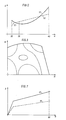
- FIG. 1 shows a spray adjuster for the actuating system according to the invention in axial section; 2 shows a diagram with the dependence of the start of delivery of the injection pump on the engine speed; 3 shows a diagram with the relationship between torque and speed of the internal combustion engine with the start of delivery of the injection pump as a parameter; FIGS. 4, 5 and 6 schematically each show an embodiment of the electronic-hydraulic actuating system according to the invention, and FIG. 7 shows a diagram with the relationship between pressure medium pressure and engine speed when the pressure medium is removed from the lubricating oil circuit of the engine.
- the drive end of the camshaft 1 of an injection pump 2 has an oblique external toothing 3.
- a hollow stub shaft 7 connected to a drive flange 6 is rotatably mounted on the extended end 5 of the camshaft 1 and secured against axial movement by means of a screw 8.
- the shaft end 7 has a straight external toothing 9 in the vicinity of its end adjacent to the oblique external toothing 3.
- the two external toothings 3 and 9 are overlapped by a sliding sleeve 10, each of which has a corresponding internal toothing 11 or 12 meshing with one of these external toothings.
- the working space for the piston 17 is from an inner end wall and an inner peripheral wall of the housing 4 and from one in the Housing 4 used guide bushing 18 limited.
- the guide bushing 18 and the housing 4 are connected to the injection pump 2 by means of screws 19.
- the housing 4 of the injection adjuster is closed with a cover 20.
- the piston 17 carries two seals 21, 22, which seal against the guide bush 18 or against the inner peripheral wall of the housing 4.
- a 3/2-way valve 23 and a 2/2-way valve 24 are attached to the housing 4 and control the inflow and outflow of the pressure medium to and from the piston 17. From the pressure medium inlet 25, the pressure medium passes through a bore 26 to the valve 23. If the plate 27 is raised by passage of current through the winding of the valve 23 designed as a solenoid valve, the pressure medium passes through a bore 28 to the end face of the piston 17 and displaces it, the rolling bearing 16, the tubular support 15 and thus also the sliding sleeve 10 against the force of the spring 13 in the direction of the drive flange 6. Further bores 29 and 30 are also filled with pressure medium which, however, cannot flow out as long as the plate 31 also Valve 24 designed as a solenoid valve remains in the closed position.
- the piston 17 is moved in the direction of the drive flange 6 until the plate 27 of the valve 23 is closed or until a state of equilibrium is established between the force exerted by the pressure medium pressure on the end face of the piston 17 and the counterforce exerted by the spring 13 .
- a movement of the piston 17 in the direction of the injection pump 2 takes place by actuating the valve 24, lifting off the plate 31 and draining the pressure medium through the bores 29, 30 and 32 into the injection adjuster.
- the spray adjuster has an outlet 33 through which the pressure medium can drain. The movement of the sliding sleeve 10 and thus of the piston 17 in the direction of the injection pump 2 is then stopped when the plate 31 closes the bore 30 and again equilibrium between the Pressure medium exerted force and the counterforce supplied by the spring 13 prevails.
- an external pressure medium return 34 is also conceivable.
- an oil inlet 35 is provided in the cover 20, by means of which, in the latter case, the toothing of the injection adjuster is supplied with the required lubricating oil in every operating position.
- the pressure medium enters the bore 28 via an inlet 36.
- the pressure medium is usually supplied by a pressure medium pump driven by the injection internal combustion engine, and there is thus essentially a monotonous relationship between the speed of the internal combustion engine and the start of delivery of the injection pump without taking special account of it Influencing factors.
- the start of delivery A of the injection pump in degrees crankshaft angle before the top dead center of the internal combustion engine is shown as a function of the speed N and the operating state in the diaqram of FIG. Curve 37 shows a desired characteristic.
- the injection pump must be started earlier.
- the start of delivery of the injection pump should be withdrawn and at full load with the maximum speed 40, the start of delivery should be brought forward again.
- Knowing the optimal start of delivery values for any engine speed and engine torque results in curves of constant start of delivery in degrees crankshaft angle before top dead center as a function of engine torque M and engine speed N, as shown in FIG.
- the actuation of the valves 23 and 24 makes it possible to set the desired start of delivery of the injection pump for each pair of values of engine speed and engine torque.
- the diagram field is limited in the direction of increasing engine torque by the engine at any speed from g ebbare largest torque and it is limited in the direction of increasing speed through the speed regulation for the prevention of damage to machine parts.
- FIG. 4 shows a first embodiment of an electronic-hydraulic control system according to the invention.
- lubricating oil is conveyed into the engine oil circuit 43 via a pump 42.
- an overpressure valve 44 opens, which means that above a predetermined speed of the internal combustion engine, the pressure is kept approximately constant, but a slightly increasing characteristic occurs with the speed.
- Such a kinked course of the oil pressure P over the engine speed N is indicated schematically at 45 in the diagram in FIG.
- the pressure prevailing in the engine oil circuit 43 is acted upon by a pressure accumulator 47 via a check valve 46.
- the inlet 36 of the valve 23 is connected via a throttle 48 to the engine oil circuit 43 and the inlet 26 of this valve is connected to the pressure accumulator 47.
- a control valve 49 with subsequent throttle 50 is connected to the connecting line between throttle 48 and inlet 36 of valve 23.
- a return line from the throttle 50 can lead directly to the oil pan 41 or, as indicated in FIG. 4, can be connected to the oil inlet 35 of the injection adjuster.
- This curve 51 also represents the pressure values available for the actuation of the spray adjuster for emergency operation in the event of failure of the electronics.
- the pressure curve 51 is a function of the engine oil viscosity and thus the engine oil temperature with constant adjustment of the throttles 48 and 50 and the control valve 49. The setting of the throttles 48 and 50 and the control valve 49 can therefore only be a compromise for an operating state.
- the pressure curve 51 according to FIG. 7 causes the piston 17 of the hydraulic spray adjuster to be pressurized via the inlet 36 and the bore 28 in such a way that the emergency operating characteristic 52 shown in broken lines in FIG. 2 results.
- the kink 53 at a low engine speed is caused by the opening of the pressure relief valve 44.
- valve 23 is energized, for example, the emergency operation is switched off and pressure oil is brought into the working space for the piston 17 of the hydraulic spray adjuster via the inlet 25 and the bores 26, 28 until the setpoint of the start of delivery of the injection pump is reached. The valve 23 then drops and the piston 17 remains in its assumed position. If it is necessary to adjust the start of delivery of the injection pump, which causes the spring 13 to relax in the hydraulic injection adjuster, the valve 24 is erreated, as a result of which the bores 29, 30 and 32 the engine oil flows into the hydraulic spray adjuster and from there via the outlet 33 into the oil pan 41.
- FIG. 5 and 6 show two variants of the actuating system according to FIG. 4, the same parts being provided with the same reference numerals.
- the solution of Figure 5 differs from that according Fi g. 4 only in that the electronic-hydraulic spray adjuster has its own oil circuit and the bore 32 is replaced by the bore 34 (see also Fig.l).
- valve 23 In order to avoid the permanent switching of the valve 23, a circuit according to FIG. 6 is conceivable. Only 2/2-way valves are used here.
- the valve 24 is the same in structure and function as in the embodiments of the actuating system according to the invention according to FIGS. 4 and 5.
- the valve 23 of these two embodiments of the actuating system in the embodiment according to FIG. 6 is replaced by two simpler valves 56 and 57.
- the oil circuit for emergency operation as in the exemplary embodiments according to FIGS. 4 and 5, can be set via throttles 48 and 50 and control valve 49. In normal operation, however, the emergency oil circuit from the bore 28 is via the 2/2-way valve 57 Cut. The valve 57 is switched so that no lubricating oil can get into the line 58 when excited.
- the adjustment of the start of delivery of the injection pump via the electronic-hydraulic injection adjuster is now done by simply switching the valves 56 and 24. If the electronics fail, the valves 56 and 24 block, whereas the valve 57 drops and an emergency operation via line 58 and the Hole 28 allows.
- the pressure accumulator 47 maintains its pressure after the internal combustion engine has been switched off. When starting, the pressure required to optimally adjust the start of delivery of the injection pump is therefore immediately available. Likewise, if the driving state changes rapidly, the pressure accumulator 47 supplies a sufficient amount of pressure medium for quickly adjusting the start of delivery of the injection pump, even in the case of small oil pumps. In the driving mode of a motor vehicle with an injection internal combustion engine and an actuating system according to the invention, in addition to the electronically controlled arbitrary load and speed-dependent adjustment of the start of delivery of the injection pump, emergency operation is possible, which can be adjusted to a certain extent to the desired injection adjuster course.
Landscapes
- Engineering & Computer Science (AREA)
- Chemical & Material Sciences (AREA)
- Combustion & Propulsion (AREA)
- Mechanical Engineering (AREA)
- General Engineering & Computer Science (AREA)
- Fuel-Injection Apparatus (AREA)
- High-Pressure Fuel Injection Pump Control (AREA)
Applications Claiming Priority (2)
| Application Number | Priority Date | Filing Date | Title |
|---|---|---|---|
| AT1351/82 | 1982-04-05 | ||
| AT135182 | 1982-04-05 |
Publications (2)
| Publication Number | Publication Date |
|---|---|
| EP0090797A1 true EP0090797A1 (fr) | 1983-10-05 |
| EP0090797B1 EP0090797B1 (fr) | 1986-06-11 |
Family
ID=3512011
Family Applications (1)
| Application Number | Title | Priority Date | Filing Date |
|---|---|---|---|
| EP83890050A Expired EP0090797B1 (fr) | 1982-04-05 | 1983-03-30 | Système de réglage électro-hydraulique du début de refoulement d'une pompe d'injection d'un moteur à combustion interne à injection |
Country Status (3)
| Country | Link |
|---|---|
| EP (1) | EP0090797B1 (fr) |
| AT (1) | ATE20377T1 (fr) |
| DE (1) | DE3364046D1 (fr) |
Cited By (2)
| Publication number | Priority date | Publication date | Assignee | Title |
|---|---|---|---|---|
| GB2161624A (en) * | 1984-07-12 | 1986-01-15 | Lucas Ind Plc | Fuel pumping apparatus |
| FR2972493A1 (fr) * | 2011-03-11 | 2012-09-14 | Manitou Bf | Dispositif de controle de regime moteur |
Citations (4)
| Publication number | Priority date | Publication date | Assignee | Title |
|---|---|---|---|---|
| GB579504A (en) * | 1943-05-14 | 1946-08-06 | Bendix Aviat Corp | Coupling means for shafts and like torque-transmitting members |
| FR2030975A5 (fr) * | 1969-06-27 | 1970-11-13 | Bosch | |
| US3815564A (en) * | 1971-03-06 | 1974-06-11 | Nippon Denso Co | Fuel injection device for internal combustion engines |
| GB2059114A (en) * | 1979-08-11 | 1981-04-15 | Daimler Benz Ag | Injection timing means for fuel injection in an internal-combustion engine |
-
1983
- 1983-03-30 EP EP83890050A patent/EP0090797B1/fr not_active Expired
- 1983-03-30 DE DE8383890050T patent/DE3364046D1/de not_active Expired
- 1983-03-30 AT AT83890050T patent/ATE20377T1/de active
Patent Citations (4)
| Publication number | Priority date | Publication date | Assignee | Title |
|---|---|---|---|---|
| GB579504A (en) * | 1943-05-14 | 1946-08-06 | Bendix Aviat Corp | Coupling means for shafts and like torque-transmitting members |
| FR2030975A5 (fr) * | 1969-06-27 | 1970-11-13 | Bosch | |
| US3815564A (en) * | 1971-03-06 | 1974-06-11 | Nippon Denso Co | Fuel injection device for internal combustion engines |
| GB2059114A (en) * | 1979-08-11 | 1981-04-15 | Daimler Benz Ag | Injection timing means for fuel injection in an internal-combustion engine |
Non-Patent Citations (1)
| Title |
|---|
| PATENTS ABSTRACTS OF JAPAN, Band 6, Nr. 48, 27. März 1982, Seite 926 M 119 & JP - A - 56 162 230 (DIESEL KIKI K.K.) 14.12.1981 * |
Cited By (2)
| Publication number | Priority date | Publication date | Assignee | Title |
|---|---|---|---|---|
| GB2161624A (en) * | 1984-07-12 | 1986-01-15 | Lucas Ind Plc | Fuel pumping apparatus |
| FR2972493A1 (fr) * | 2011-03-11 | 2012-09-14 | Manitou Bf | Dispositif de controle de regime moteur |
Also Published As
| Publication number | Publication date |
|---|---|
| ATE20377T1 (de) | 1986-06-15 |
| EP0090797B1 (fr) | 1986-06-11 |
| DE3364046D1 (en) | 1986-07-17 |
Similar Documents
| Publication | Publication Date | Title |
|---|---|---|
| EP0335083B1 (fr) | Dispositif de déplacement angulaire relatif entre deux arbres en liaison d'entraînement | |
| DE2503346C2 (de) | Kraftstoffverteilereinspritzpumpe für Brennkraftmaschinen | |
| DE112007002915B4 (de) | Verstelleinrichtung zur Phaseneinstellung einer Nockenwelle | |
| DE3144500C2 (de) | Mit einem hydraulischen Spritzversteller versehene Verteilereinspritzpumpe | |
| DE60123699T2 (de) | Hydraulische Servolenkung für ein Fahrzeug | |
| EP0469332A1 (fr) | Procédé pour changer le calage des soupapes d'un moteur à combustion interne | |
| DE10237801A1 (de) | Vorrichtung zur Druckregelung von Hydraulikpumpen | |
| DE10141786B4 (de) | Einrichtung zur Regelung des Schmieröldruckes einer Brennkraftmaschine | |
| DE2844910A1 (de) | Kraftstoffeinspritzpumpe fuer brennkraftmaschinen | |
| DE1258187B (de) | Kraftstoffeinspritzpumpe fuer Brennkraftmaschinen | |
| WO1993024346A1 (fr) | Pompe hydraulique entrainee par un moteur a combustion interne | |
| WO2003058071A1 (fr) | Dispositif pour reguler la pression de pompes hydrauliques | |
| DE3911160C2 (de) | Kraftstoffeinspritzpumpe für Brennkraftmaschinen | |
| EP0461213B1 (fr) | Pompe d'injection de carburant pour moteurs a combustion interne | |
| EP0090797B1 (fr) | Système de réglage électro-hydraulique du début de refoulement d'une pompe d'injection d'un moteur à combustion interne à injection | |
| EP0273225A2 (fr) | Pompe d'injection de combustible pour moteurs à combustion interne | |
| EP0543805B1 (fr) | Pompe d'injection de carburant pour moteurs a combustion interne | |
| DE1920417C3 (de) | Kraftstoffverteilereinspritzpumpe fur eine Brennkraftmaschine | |
| EP0323591A2 (fr) | Dispositif de réglage de l'injection à 2 points | |
| DE3014313A1 (de) | Verteiler-einspritzpumpe fuer brennkraftmaschinen | |
| DE2630385A1 (de) | Kraftstoffeinspritzvorrichtung | |
| DE3215047C2 (de) | Brennstoffeinspritzsystem für eine Brennkraftmaschine | |
| DE3900346A1 (de) | Kraftstoffeinspritzpumpe fuer brennkraftmaschinen | |
| EP1049860A1 (fr) | Pompe d'injection de carburant | |
| EP0812384B1 (fr) | Pompe d'injection de carburant pour moteur a combustion interne |
Legal Events
| Date | Code | Title | Description |
|---|---|---|---|
| PUAI | Public reference made under article 153(3) epc to a published international application that has entered the european phase |
Free format text: ORIGINAL CODE: 0009012 |
|
| AK | Designated contracting states |
Kind code of ref document: A1 Designated state(s): AT DE FR GB Designated state(s): AT DE FR GB |
|
| 17P | Request for examination filed |
Effective date: 19840306 |
|
| GRAA | (expected) grant |
Free format text: ORIGINAL CODE: 0009210 |
|
| AK | Designated contracting states |
Kind code of ref document: B1 Designated state(s): AT DE FR GB |
|
| REF | Corresponds to: |
Ref document number: 20377 Country of ref document: AT Date of ref document: 19860615 Kind code of ref document: T |
|
| REF | Corresponds to: |
Ref document number: 3364046 Country of ref document: DE Date of ref document: 19860717 |
|
| ET | Fr: translation filed | ||
| PLBI | Opposition filed |
Free format text: ORIGINAL CODE: 0009260 |
|
| 26 | Opposition filed |
Opponent name: KLOECKNER-HUMBOLDT-DEUTZ AG Effective date: 19870306 |
|
| RAP2 | Party data changed (patent owner data changed or rights of a patent transferred) |
Owner name: ROBERT BOSCH AG |
|
| PLBN | Opposition rejected |
Free format text: ORIGINAL CODE: 0009273 |
|
| STAA | Information on the status of an ep patent application or granted ep patent |
Free format text: STATUS: OPPOSITION REJECTED |
|
| 27O | Opposition rejected |
Effective date: 19890204 |
|
| PGFP | Annual fee paid to national office [announced via postgrant information from national office to epo] |
Ref country code: AT Payment date: 19910308 Year of fee payment: 9 |
|
| PGFP | Annual fee paid to national office [announced via postgrant information from national office to epo] |
Ref country code: FR Payment date: 19910319 Year of fee payment: 9 |
|
| PGFP | Annual fee paid to national office [announced via postgrant information from national office to epo] |
Ref country code: GB Payment date: 19910320 Year of fee payment: 9 |
|
| PGFP | Annual fee paid to national office [announced via postgrant information from national office to epo] |
Ref country code: DE Payment date: 19910531 Year of fee payment: 9 |
|
| PG25 | Lapsed in a contracting state [announced via postgrant information from national office to epo] |
Ref country code: GB Effective date: 19920330 Ref country code: AT Effective date: 19920330 |
|
| GBPC | Gb: european patent ceased through non-payment of renewal fee | ||
| PG25 | Lapsed in a contracting state [announced via postgrant information from national office to epo] |
Ref country code: FR Effective date: 19921130 |
|
| PG25 | Lapsed in a contracting state [announced via postgrant information from national office to epo] |
Ref country code: DE Effective date: 19921201 |
|
| REG | Reference to a national code |
Ref country code: FR Ref legal event code: ST |