EP0090871A1 - Détecteur à haute pression - Google Patents
Détecteur à haute pression Download PDFInfo
- Publication number
- EP0090871A1 EP0090871A1 EP82102929A EP82102929A EP0090871A1 EP 0090871 A1 EP0090871 A1 EP 0090871A1 EP 82102929 A EP82102929 A EP 82102929A EP 82102929 A EP82102929 A EP 82102929A EP 0090871 A1 EP0090871 A1 EP 0090871A1
- Authority
- EP
- European Patent Office
- Prior art keywords
- sealing
- sensor
- sensor part
- mounting hole
- base body
- Prior art date
- Legal status (The legal status is an assumption and is not a legal conclusion. Google has not performed a legal analysis and makes no representation as to the accuracy of the status listed.)
- Granted
Links
- 238000007789 sealing Methods 0.000 claims abstract description 79
- 239000012528 membrane Substances 0.000 claims abstract description 25
- 239000002184 metal Substances 0.000 claims description 3
- 229910052751 metal Inorganic materials 0.000 claims description 3
- 230000000694 effects Effects 0.000 abstract description 8
- 238000009530 blood pressure measurement Methods 0.000 abstract description 4
- 230000004907 flux Effects 0.000 abstract 1
- 238000005259 measurement Methods 0.000 description 14
- 238000011161 development Methods 0.000 description 6
- 230000018109 developmental process Effects 0.000 description 6
- 238000009434 installation Methods 0.000 description 6
- 238000000034 method Methods 0.000 description 5
- 230000008569 process Effects 0.000 description 5
- 238000010276 construction Methods 0.000 description 4
- 238000005516 engineering process Methods 0.000 description 4
- 230000035945 sensitivity Effects 0.000 description 4
- 239000013078 crystal Substances 0.000 description 3
- 239000007788 liquid Substances 0.000 description 3
- 229910000831 Steel Inorganic materials 0.000 description 2
- 230000008901 benefit Effects 0.000 description 2
- 238000013461 design Methods 0.000 description 2
- 239000000243 solution Substances 0.000 description 2
- 239000010959 steel Substances 0.000 description 2
- RYGMFSIKBFXOCR-UHFFFAOYSA-N Copper Chemical group [Cu] RYGMFSIKBFXOCR-UHFFFAOYSA-N 0.000 description 1
- 230000002411 adverse Effects 0.000 description 1
- 230000003679 aging effect Effects 0.000 description 1
- 238000005452 bending Methods 0.000 description 1
- 230000015572 biosynthetic process Effects 0.000 description 1
- 230000008859 change Effects 0.000 description 1
- 238000002485 combustion reaction Methods 0.000 description 1
- 238000005520 cutting process Methods 0.000 description 1
- 238000006073 displacement reaction Methods 0.000 description 1
- 238000005553 drilling Methods 0.000 description 1
- 230000005489 elastic deformation Effects 0.000 description 1
- 239000003721 gunpowder Substances 0.000 description 1
- 230000006872 improvement Effects 0.000 description 1
- 238000002347 injection Methods 0.000 description 1
- 239000007924 injection Substances 0.000 description 1
- 238000005461 lubrication Methods 0.000 description 1
- 238000004519 manufacturing process Methods 0.000 description 1
- 230000004048 modification Effects 0.000 description 1
- 238000012986 modification Methods 0.000 description 1
- 230000035515 penetration Effects 0.000 description 1
- 239000000843 powder Substances 0.000 description 1
- 230000036316 preload Effects 0.000 description 1
- 238000003825 pressing Methods 0.000 description 1
- 239000010453 quartz Substances 0.000 description 1
- 238000011160 research Methods 0.000 description 1
- 230000004043 responsiveness Effects 0.000 description 1
- 238000010079 rubber tapping Methods 0.000 description 1
- 238000000926 separation method Methods 0.000 description 1
- VYPSYNLAJGMNEJ-UHFFFAOYSA-N silicon dioxide Inorganic materials O=[Si]=O VYPSYNLAJGMNEJ-UHFFFAOYSA-N 0.000 description 1
- 230000003068 static effect Effects 0.000 description 1
- 239000000725 suspension Substances 0.000 description 1
- 230000009466 transformation Effects 0.000 description 1
Images
Classifications
-
- G—PHYSICS
- G01—MEASURING; TESTING
- G01L—MEASURING FORCE, STRESS, TORQUE, WORK, MECHANICAL POWER, MECHANICAL EFFICIENCY, OR FLUID PRESSURE
- G01L5/00—Apparatus for, or methods of, measuring force, work, mechanical power, or torque, specially adapted for specific purposes
- G01L5/14—Apparatus for, or methods of, measuring force, work, mechanical power, or torque, specially adapted for specific purposes for measuring the force of explosions; for measuring the energy of projectiles
-
- G—PHYSICS
- G01—MEASURING; TESTING
- G01L—MEASURING FORCE, STRESS, TORQUE, WORK, MECHANICAL POWER, MECHANICAL EFFICIENCY, OR FLUID PRESSURE
- G01L23/00—Devices or apparatus for measuring or indicating or recording rapid changes, such as oscillations, in the pressure of steam, gas, or liquid; Indicators for determining work or energy of steam, internal-combustion, or other fluid-pressure engines from the condition of the working fluid
- G01L23/08—Devices or apparatus for measuring or indicating or recording rapid changes, such as oscillations, in the pressure of steam, gas, or liquid; Indicators for determining work or energy of steam, internal-combustion, or other fluid-pressure engines from the condition of the working fluid operated electrically
- G01L23/10—Devices or apparatus for measuring or indicating or recording rapid changes, such as oscillations, in the pressure of steam, gas, or liquid; Indicators for determining work or energy of steam, internal-combustion, or other fluid-pressure engines from the condition of the working fluid operated electrically by pressure-sensitive members of the piezoelectric type
-
- G—PHYSICS
- G01—MEASURING; TESTING
- G01L—MEASURING FORCE, STRESS, TORQUE, WORK, MECHANICAL POWER, MECHANICAL EFFICIENCY, OR FLUID PRESSURE
- G01L9/00—Measuring steady of quasi-steady pressure of fluid or fluent solid material by electric or magnetic pressure-sensitive elements; Transmitting or indicating the displacement of mechanical pressure-sensitive elements, used to measure the steady or quasi-steady pressure of a fluid or fluent solid material, by electric or magnetic means
- G01L9/0041—Transmitting or indicating the displacement of flexible diaphragms
- G01L9/008—Transmitting or indicating the displacement of flexible diaphragms using piezoelectric devices
Definitions
- the invention relates to high-pressure transducers for fastening in a mounting hole in a component, with a base body, a sensor part connected to the base body with a membrane section for loading a sensor element and a device for creating a seal between the sensor and the mounting hole.
- the invention is therefore directed in particular, but not exclusively, to pressure sensors for detecting such high pressures. Therefore, a preferred field of application is the ballistic pressure measurements to determine at guns and guns the pressure curve during the A bschusses of the projectile. Such measurements are necessary for research purposes in the further development of pipes and projectiles. Corresponding measurements are carried out in so-called pressure bombs for powder development. Another area of application is high-pressure measurement in liquid media. In all cases, these are processes that last a few milliseconds and have pressure amplitudes up to 10,000 bar.
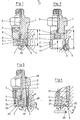
- Fig. 1 shows a typical known piezoelectric high pressure transducer with a blind hole seal. Due to the high sealing torques during installation, there are still no transducers on the market whose sensitivity is not affected by the assembly process. This is due to the fact that the force flow lines introduced into the transducer during assembly are passed through sensitive sensor parts, as a result of which deformations are also transmitted to the membrane parts of the transducer. Depending on the micro design of the sealing section, there is a different sensitivity for each installation, so that it is often impossible to achieve satisfactory measurement accuracy and repeatability.
- the invention has for its object to provide transducers of the type in question, which are practically insensitive to different sealing torques.
- a solution to this problem which is primarily suitable for measuring pressures in liquid media, is characterized in that the sensor part with its membrane section is arranged or set back at such a distance from the device that creates the seal between the transducer and the mounting hole that the lines of force flow arising during the sealing of the transducer are essentially kept away from the sensor part from the sealing forces.
- the senor part can be preceded by a tubular extension with an external thread for screwing into the mounting hole, the tubular extension with its sealing surface being able to be brought into sealing engagement with a shoulder surface of the mounting hole.
- Another preferred solution to the problem on which the invention is based is characterized by a flange-like sealing part which is connected to the sensor part in the region of the membrane and which is pressed in sealing engagement with a shoulder surface of the mounting hole by a mounting screw surrounding the base body, so that the sealing of the transducer force flow lines arising from the sealing forces are essentially kept away from the sensor part.
- any deformation of the collar caused by the sealing forces has an effect on the sensitive sensor part and the force flow lines resulting from the sealing forces not only penetrate the collar, but also the sensor part.
- the effects of the sealing forces are essentially limited to the flange-like sealing part which is connected to the sensor part in the region of the membrane part and which, according to a development of the invention, can preferably be elastically connected to the sensor part. Since, according to the invention, the assembly hollow screw preferably surrounds the sensor part of the base body at a distance, deformations of the assembly hollow screw cannot have an effect on the sensor part when it is screwed into the mounting hole.
- Both types of transducer are used to measure rapidly changing pressure sequences with high peak values and are characterized by a high level of consistency in their responsiveness as well as a long service life, since in both cases the sensitive membrane area of the transducer is not or only barely noticeable due to the sealing forces is charged.
- the sensitivity of the transducers is neither influenced by the amount of the tightening torque when screwing into the mounting hole, nor by the elastic boundary conditions of the mounting hole, nor by the aging effect. This ensures that both the measurement accuracy itself and its reproducibility remain unchanged regardless of the respective installation conditions.
- Fig. 1 shows a known high pressure transducer with a blind hole seal. This type of seal is easier to manufacture, but has the disadvantage that the membrane section 7 cannot be installed flush with the surface of the pressure chamber, so that a supply bore 30 is always necessary. Because of the required high accuracy of the drilling, surface lapping and tapping work to be carried out, the special tools are supplied by the transducer manufacturer.
- the known transducer comprises a mounting base body 1 with an external thread 2 for screwing into a threaded mounting hole 11 such that the free under face 3 of a sensor part 4 fastened to the base body comes into sealing engagement with a shoulder surface of the feed bore 30.
- a sensor element 5 is arranged in a recess in the sensor part 4, which is preferably one or more suitable piezo crystals, the electrical charges of which are discharged to the outside via a signal line 6 led through the mounting body 1.
- the free lower end face of the transducer is formed in part by an inner thickened membrane section 7 that transmits the pressure signal edientik p generated by the M as a force on the sensor element 5 and is preferably made with the sensor part 4 in one piece.
- the sensor part 4 itself is supplied with the mounting body 1 turned upper contact surface 8 on the mounting base body 1, as indicated at 9, welded.
- the medium pressure p acts on the membrane section 7 up to the sealing surface 3.
- the pressure force transformation is thus carried out in an extremely complex structure.
- the necessary pressing force of the sealing surface 3 against the shoulder surface of the feed bore 3o is provided when the mounting body is screwed into the bore section T. Sealing torques of 30 ... 60 Nm are necessary for this.
- force flow lines K also extend to sensitive sensor parts.
- the medium pressure p forces the static force flow lines K to change, which in turn has an effect on the sensor sensitivity.
- the thermal component of a gas surge which results in additional tensioning of the membrane section 7, has a further significant influence on the membrane section 7, which can result in dynamic errors in the measurement.
- the sensor part 4 Due to the construction, the sensor part 4 is penetrated by the force air lines K and torsional forces over the entire height. Accordingly, there are considerable adverse influences on the clamping of the sensor element 5 and the membrane section. An additional problem is the upper, large separating or supporting surface 8, which, depending on the design of the weld 9, led to more or less gap suspension, which should be avoided as far as possible.
- FIG. 2 shows a high-pressure sensor according to the first embodiment of the invention, which is particularly suitable for measuring the pressures in liquid media.
- the mounting body 1 is in turn connected or welded to the sensor part 4 at 9.
- a lower tubular extension 10 is formed on the sensor part 4, so that the membrane section 7 no longer forms the lower outer end face of the transducer as in the known construction previously described in connection with FIG. 1, but by a suitable distance from the lower one Sealing surface 3 on the tubular extension 10 is set back upwards.
- the tubular extension 10 has on its outer circumference a thread 2 with which the transducer can be screwed into the mounting hole 11 of the component to be examined in order to bring the end or sealing surface 3 of the tubular extension 10 into sealing engagement with the heel surface of the mounting hole.
- the pressure p thus acts on the diaphragm section 7 via the space 12 enclosed by the tubular extension 10.
- the force flow lines K which extend from the lowest threads to the sealing surface 3, run essentially only through parts of the transducer which exert no influence on the sensor element 5, so that in this embodiment it is ensured that the measurement value acquisition is not influenced by the level of the tightening torques and the like when the sensor is installed in the mounting hole.
- the transducer corresponds to Fig. 2 essentially of the known construction described above, so that a new description of these parts is unnecessary.
- the senor according to the preferred embodiment of the invention again comprises a base body 1, which, however, is here preferably integrally connected to the sensor part 4.
- the sensor part 4 carries at its lower end a membrane section 7 which is exposed to the media pressure p and which acts on a sensor element 5 accommodated in the sensor part of the type described in connection with FIGS. 1 and 2.
- a signal line passing through the base body 1 leads the charges arising at the sensor element 5 to the outside.
- the base body 1, as shown, is surrounded on the outside by a hollow screw 21, which can be screwed with its external thread 2 relatively far into the mounting hole 11 of the component to be examined.
- the mounting screw On its lower end surface 23, the mounting screw is in contact with a flange-like sealing part 22, which protrudes horizontally outwards from the sensor part 4 or is firmly connected to the latter via a weld seam 24.
- the tubular extension 10 shown in FIG. 2 is thus avoided and its function is replaced by the sealing part 22, on which there is no longer any thread.
- connection between the sealing part 22 and the sensor part 4 is made elastic according to the invention.
- screwings 25 and 26 can be introduced at suitable points between the sealing part 22 and the sensor part 4, which create a weakened connection of the sealing part 22 to the sensor part 4 and thereby prevent the lines of force flow from the sealing part 22 into the sensor part 4 can.
- the extent to which the sealing part 22 is weakened by the turns 25 and 26 or to what extent the connection T between the sensor part 4 and the sealing part 22 can be reduced in thickness T depends on the pressure p to be measured, which is to be sealed, and also of the other operating conditions. Trials have shown that the Thickness t of the connecting web between sealing part 22 and sensor part 4 should preferably not be greater than about 25% of the front diameter of the sensor.
- Another advantage of the provision of a hollow screw 21 is that the overall height of the sealing part 22 and its connection to the sensor part 4 can be very small, as a result of which the force flow lines run only a short distance in the vicinity of the sensor part 4 and accordingly only can have a slight effect on the sensor part 4 or its membrane section 7.
- the hollow screw 21 only touches the base body 1 at an upper area, while in the area of the sensor part 4 there is a distance between it and the hollow screw, so that any deformations of the hollow screw do not affect the Can affect sensor part 4.
- a groove for receiving a securing ring 21 can be introduced in the upper region of the base body 1, which further fixes the hollow mounting screw 21.
- the membrane part 7 or the sensor part 4 is set back somewhat upwards relative to the sealing surface 3, as a result of which the pressure medium is spread over the whole Distribute membrane section 7 and the latter is acted upon by the measuring pressure over a precisely defined area.
- F ig. 4 shows a partial view of a modified high-pressure transducer according to the invention with a blind hole seal.
- a metal sealing ring 27 engages when installing the transducer, which is described in detail in DE-PS 17 75 646.
- the metal sealing ring 27 is a pipe section 28, cf. Fig. 4 below, which assumes the configuration shown in Fig. 4 by elastic deformation during installation and results in a perfect seal even with very small tightening torques.
- 4 also shows in more detail the formation of the elastic connection of the sealing part 22 to the sensor part 4 by means of the recesses 25 and 26.
Landscapes
- Physics & Mathematics (AREA)
- General Physics & Mathematics (AREA)
- Chemical & Material Sciences (AREA)
- Engineering & Computer Science (AREA)
- Combustion & Propulsion (AREA)
- Measuring Fluid Pressure (AREA)
Priority Applications (4)
| Application Number | Priority Date | Filing Date | Title |
|---|---|---|---|
| DE8282102929T DE3275009D1 (en) | 1982-04-06 | 1982-04-06 | High-pressure detector |
| AT82102929T ATE24764T1 (de) | 1982-04-06 | 1982-04-06 | Hochdruckaufnehmer. |
| EP82102929A EP0090871B1 (fr) | 1982-04-06 | 1982-04-06 | Détecteur à haute pression |
| US06/481,881 US4559821A (en) | 1982-04-06 | 1983-04-04 | High pressure transducer |
Applications Claiming Priority (1)
| Application Number | Priority Date | Filing Date | Title |
|---|---|---|---|
| EP82102929A EP0090871B1 (fr) | 1982-04-06 | 1982-04-06 | Détecteur à haute pression |
Publications (2)
| Publication Number | Publication Date |
|---|---|
| EP0090871A1 true EP0090871A1 (fr) | 1983-10-12 |
| EP0090871B1 EP0090871B1 (fr) | 1987-01-07 |
Family
ID=8188972
Family Applications (1)
| Application Number | Title | Priority Date | Filing Date |
|---|---|---|---|
| EP82102929A Expired EP0090871B1 (fr) | 1982-04-06 | 1982-04-06 | Détecteur à haute pression |
Country Status (4)
| Country | Link |
|---|---|
| US (1) | US4559821A (fr) |
| EP (1) | EP0090871B1 (fr) |
| AT (1) | ATE24764T1 (fr) |
| DE (1) | DE3275009D1 (fr) |
Cited By (8)
| Publication number | Priority date | Publication date | Assignee | Title |
|---|---|---|---|---|
| EP0230491A1 (fr) * | 1986-01-22 | 1987-08-05 | Kristal Instrumente AG | Capteur, en particulier pour des mesures de haute pression |
| DE8903667U1 (de) * | 1989-03-23 | 1989-05-11 | Kistler Instrumente Ag, Winterthur | Hochdruckaufnehmer |
| EP0395622A3 (fr) * | 1989-03-30 | 1991-06-05 | AVL Gesellschaft für Verbrennungskraftmaschinen und Messtechnik mbH.Prof.Dr.Dr.h.c. Hans List | Capteur de pression |
| EP0616203A1 (fr) * | 1993-03-19 | 1994-09-21 | General Motors Corporation | Capteur de pression de cylindre d'un moteur |
| DE102009039827A1 (de) | 2008-09-11 | 2010-04-15 | Piezocryst Advanced Sensorics Gmbh | Piezoelektrischer Drucksensor |
| EP1639335B1 (fr) * | 2003-06-19 | 2012-04-18 | Dynisco Instruments Llc | Transducteur de pression |
| EP2110540A3 (fr) * | 2008-04-15 | 2016-03-16 | Denso Corporation | Injecteur de carburant avec un capteur de pression de carburant |
| US9546676B2 (en) | 2012-08-16 | 2017-01-17 | Robert Bosch Gmbh | Thread connection for connecting components conducting high pressure medium |
Families Citing this family (18)
| Publication number | Priority date | Publication date | Assignee | Title |
|---|---|---|---|---|
| DE3811311C1 (fr) * | 1988-04-02 | 1989-03-09 | Robert Bosch Gmbh, 7000 Stuttgart, De | |
| US4969352A (en) * | 1989-08-21 | 1990-11-13 | General Motors Corporation | Combustion pressure sensor |
| DE4230031A1 (de) * | 1991-09-09 | 1993-03-11 | Avl Verbrennungskraft Messtech | Drucksensor |
| FR2703772B1 (fr) * | 1993-04-10 | 1995-05-19 | Bosch Gmbh Robert | Douille de pression, notamment pour un capteur de cognement. |
| CH691625A5 (de) * | 1997-09-15 | 2001-08-31 | Kk Holding Ag | Beschleunigungskompensierter Druckkaufnehmer. |
| DE10318679A1 (de) * | 2003-04-24 | 2004-12-30 | Vega Grieshaber Kg | Befestigungsanordnung für einen Sensor an einem Behältnis |
| US7197918B2 (en) * | 2003-08-14 | 2007-04-03 | International Engine Intellectual Property Company, Llc | Apparatus and method for evaluating fuel injectors |
| DE102005011973B4 (de) * | 2005-03-13 | 2012-04-19 | Endress + Hauser Gmbh + Co. Kg | Sensormodul |
| CN101636592A (zh) * | 2006-07-20 | 2010-01-27 | 费尔柴尔德工业产品公司 | 高压变换器 |
| JP4840098B2 (ja) * | 2006-11-20 | 2011-12-21 | トヨタ自動車株式会社 | 圧力センサ |
| WO2015066310A1 (fr) * | 2013-10-30 | 2015-05-07 | Lime Instruments Llc | Ensemble capteur pour mesure de pression dynamique dans des pompes alternatives |
| JP6404776B2 (ja) * | 2015-06-09 | 2018-10-17 | 株式会社Soken | 燃焼圧センサ |
| US9689534B2 (en) * | 2015-11-11 | 2017-06-27 | Chad Deville | Pipeline-waste-gas reduction method |
| US9695988B2 (en) * | 2015-11-11 | 2017-07-04 | Chad Deville | Pipeline-waste-gas reducer apparatus |
| US9995619B2 (en) | 2016-05-13 | 2018-06-12 | Adaptec Medical Devices LLC | Fluid container measurement system employing load cell linkage member |
| US10444060B2 (en) | 2016-05-13 | 2019-10-15 | Adaptec Medical Devices LLC | Fluid container measurement system |
| CN108151639B (zh) * | 2017-12-18 | 2023-09-01 | 中船重工西安东仪科工集团有限公司 | 一种耐压密封装配体内部零件位移精密测量装置 |
| ES3056549T3 (en) * | 2022-12-07 | 2026-02-23 | Kistler Holding Ag | Pressure sensor, system for assembling and disassembling the pressure sensor, and use of the pressure sensor |
Family Cites Families (6)
| Publication number | Priority date | Publication date | Assignee | Title |
|---|---|---|---|---|
| US2629801A (en) * | 1950-08-01 | 1953-02-24 | Howard D Warshaw | Mounting for pressure responsive device |
| US3247719A (en) * | 1963-10-01 | 1966-04-26 | Chelner Herbert | Strain decoupled transducer |
| US3225859A (en) * | 1964-03-30 | 1965-12-28 | Lawrence C Davidson | Pipe line hydrophone system |
| US3335381A (en) * | 1965-07-06 | 1967-08-08 | Stratham Instr Inc | Duplex flexure for force transducer |
| US3587322A (en) * | 1969-06-17 | 1971-06-28 | Simmonds Precision Products | Pressure transducer mounting |
| CH582353A5 (fr) * | 1974-11-08 | 1976-11-30 | Kistler Instrumente Ag |
-
1982
- 1982-04-06 AT AT82102929T patent/ATE24764T1/de not_active IP Right Cessation
- 1982-04-06 EP EP82102929A patent/EP0090871B1/fr not_active Expired
- 1982-04-06 DE DE8282102929T patent/DE3275009D1/de not_active Expired
-
1983
- 1983-04-04 US US06/481,881 patent/US4559821A/en not_active Expired - Fee Related
Cited By (8)
| Publication number | Priority date | Publication date | Assignee | Title |
|---|---|---|---|---|
| EP0230491A1 (fr) * | 1986-01-22 | 1987-08-05 | Kristal Instrumente AG | Capteur, en particulier pour des mesures de haute pression |
| DE8903667U1 (de) * | 1989-03-23 | 1989-05-11 | Kistler Instrumente Ag, Winterthur | Hochdruckaufnehmer |
| EP0395622A3 (fr) * | 1989-03-30 | 1991-06-05 | AVL Gesellschaft für Verbrennungskraftmaschinen und Messtechnik mbH.Prof.Dr.Dr.h.c. Hans List | Capteur de pression |
| EP0616203A1 (fr) * | 1993-03-19 | 1994-09-21 | General Motors Corporation | Capteur de pression de cylindre d'un moteur |
| EP1639335B1 (fr) * | 2003-06-19 | 2012-04-18 | Dynisco Instruments Llc | Transducteur de pression |
| EP2110540A3 (fr) * | 2008-04-15 | 2016-03-16 | Denso Corporation | Injecteur de carburant avec un capteur de pression de carburant |
| DE102009039827A1 (de) | 2008-09-11 | 2010-04-15 | Piezocryst Advanced Sensorics Gmbh | Piezoelektrischer Drucksensor |
| US9546676B2 (en) | 2012-08-16 | 2017-01-17 | Robert Bosch Gmbh | Thread connection for connecting components conducting high pressure medium |
Also Published As
| Publication number | Publication date |
|---|---|
| ATE24764T1 (de) | 1987-01-15 |
| US4559821A (en) | 1985-12-24 |
| DE3275009D1 (en) | 1987-02-12 |
| EP0090871B1 (fr) | 1987-01-07 |
Similar Documents
| Publication | Publication Date | Title |
|---|---|---|
| EP0090871A1 (fr) | Détecteur à haute pression | |
| EP0090872B1 (fr) | Détecteur à haute pression | |
| DE3122375C2 (de) | Sensoranordnung | |
| DE4234290C2 (de) | Drucksensor | |
| DE2544505C3 (de) | Druckaufnehmer | |
| DE102009030702A1 (de) | Drucksensormesselement sowie damit versehener Drucksensor | |
| EP0230491B1 (fr) | Capteur, en particulier pour des mesures de haute pression | |
| EP0915327B1 (fr) | Capteur de pression | |
| AT394112B (de) | Druckaufnehmer | |
| DE2649358A1 (de) | Einrichtung zur erfassung des innendruckes in einem drucksystem | |
| EP0041599B1 (fr) | Capteur de force, en particulier pour mesures de pressions ballistiques | |
| EP0140066A1 (fr) | Dispositif pour la détection de forces, tensions resp. des accélérations de machines, appareils ou similaires | |
| EP2174106B1 (fr) | Capteur de force | |
| EP2087333A2 (fr) | Capteur de pression pour effectuer des mesures dans le cadre de processus dynamiques à haute température | |
| DE3640511A1 (de) | Verfahren und vorrichtung zur ueberpruefung und/oder erfassung der masse, massaenderungen, positionen oder positionsaenderungen von werkstuecken, stellgliedern oder dgl. | |
| DE2552873C2 (de) | Hydraulisches Spannelement | |
| EP3899470B1 (fr) | Capteur de pression avec moyen pour deplacer une membrane isolante | |
| DE69106411T2 (de) | Piezoelektrischer Druckaufnehmer. | |
| DE4444831C2 (de) | Drucksensor | |
| DE10332284A1 (de) | Drucksensorelement mit integrierter Dichtfläche | |
| EP3798598A1 (fr) | Dispositif, procédé et système de mesure d'une tension propre d'un objet de mesure | |
| DE3327265A1 (de) | Verbesserter messwertgeber zum messen des druckes einer fluessigkeit, insbesondere einer aggressiven und heissen fluessigkeit | |
| EP1505378A1 (fr) | Système de transmission de pression | |
| DE2904844B2 (de) | Druckmeßeinrichtung zur Messung und Überwachung von Betonspannungen | |
| CH434802A (de) | Piezoelektrischer Messwandler mit einer elastischen Spannhülse zur Aufnahme des piezoelektrischen Kristallsatzes |
Legal Events
| Date | Code | Title | Description |
|---|---|---|---|
| PUAI | Public reference made under article 153(3) epc to a published international application that has entered the european phase |
Free format text: ORIGINAL CODE: 0009012 |
|
| AK | Designated contracting states |
Designated state(s): AT CH DE FR GB LI SE |
|
| 17P | Request for examination filed |
Effective date: 19831124 |
|
| GRAA | (expected) grant |
Free format text: ORIGINAL CODE: 0009210 |
|
| AK | Designated contracting states |
Kind code of ref document: B1 Designated state(s): AT CH DE FR GB LI SE |
|
| REF | Corresponds to: |
Ref document number: 24764 Country of ref document: AT Date of ref document: 19870115 Kind code of ref document: T |
|
| REF | Corresponds to: |
Ref document number: 3275009 Country of ref document: DE Date of ref document: 19870212 |
|
| ET | Fr: translation filed | ||
| PLBE | No opposition filed within time limit |
Free format text: ORIGINAL CODE: 0009261 |
|
| STAA | Information on the status of an ep patent application or granted ep patent |
Free format text: STATUS: NO OPPOSITION FILED WITHIN TIME LIMIT |
|
| 26N | No opposition filed | ||
| PGFP | Annual fee paid to national office [announced via postgrant information from national office to epo] |
Ref country code: FR Payment date: 19910228 Year of fee payment: 10 |
|
| PGFP | Annual fee paid to national office [announced via postgrant information from national office to epo] |
Ref country code: SE Payment date: 19910312 Year of fee payment: 10 |
|
| PGFP | Annual fee paid to national office [announced via postgrant information from national office to epo] |
Ref country code: GB Payment date: 19910327 Year of fee payment: 10 |
|
| PGFP | Annual fee paid to national office [announced via postgrant information from national office to epo] |
Ref country code: DE Payment date: 19910417 Year of fee payment: 10 |
|
| PGFP | Annual fee paid to national office [announced via postgrant information from national office to epo] |
Ref country code: CH Payment date: 19920305 Year of fee payment: 11 |
|
| PG25 | Lapsed in a contracting state [announced via postgrant information from national office to epo] |
Ref country code: GB Effective date: 19920406 |
|
| PG25 | Lapsed in a contracting state [announced via postgrant information from national office to epo] |
Ref country code: SE Effective date: 19920407 |
|
| GBPC | Gb: european patent ceased through non-payment of renewal fee | ||
| PG25 | Lapsed in a contracting state [announced via postgrant information from national office to epo] |
Ref country code: FR Effective date: 19921230 |
|
| PG25 | Lapsed in a contracting state [announced via postgrant information from national office to epo] |
Ref country code: DE Effective date: 19930101 |
|
| REG | Reference to a national code |
Ref country code: FR Ref legal event code: ST |
|
| PG25 | Lapsed in a contracting state [announced via postgrant information from national office to epo] |
Ref country code: LI Effective date: 19930430 Ref country code: CH Effective date: 19930430 |
|
| REG | Reference to a national code |
Ref country code: CH Ref legal event code: PL |
|
| PGFP | Annual fee paid to national office [announced via postgrant information from national office to epo] |
Ref country code: AT Payment date: 19940331 Year of fee payment: 13 |
|
| EUG | Se: european patent has lapsed |
Ref document number: 82102929.5 Effective date: 19921108 |
|
| PG25 | Lapsed in a contracting state [announced via postgrant information from national office to epo] |
Ref country code: AT Effective date: 19950406 |