EP0090885B1 - Dispositif de manoeuvre à pression de fluide - Google Patents
Dispositif de manoeuvre à pression de fluide Download PDFInfo
- Publication number
- EP0090885B1 EP0090885B1 EP82109716A EP82109716A EP0090885B1 EP 0090885 B1 EP0090885 B1 EP 0090885B1 EP 82109716 A EP82109716 A EP 82109716A EP 82109716 A EP82109716 A EP 82109716A EP 0090885 B1 EP0090885 B1 EP 0090885B1
- Authority
- EP
- European Patent Office
- Prior art keywords
- pressure medium
- piston
- sleeve
- actuator according
- adjustment actuator
- Prior art date
- Legal status (The legal status is an assumption and is not a legal conclusion. Google has not performed a legal analysis and makes no representation as to the accuracy of the status listed.)
- Expired
Links
- 230000007246 mechanism Effects 0.000 claims description 26
- 238000007789 sealing Methods 0.000 claims description 15
- 241001052209 Cylinder Species 0.000 claims 1
- 210000002310 elbow joint Anatomy 0.000 claims 1
- 238000012856 packing Methods 0.000 claims 1
- 230000000712 assembly Effects 0.000 description 5
- 238000000429 assembly Methods 0.000 description 5
- 238000003825 pressing Methods 0.000 description 4
- 210000000629 knee joint Anatomy 0.000 description 3
- 239000000463 material Substances 0.000 description 2
- 229910000831 Steel Inorganic materials 0.000 description 1
- 230000006835 compression Effects 0.000 description 1
- 238000007906 compression Methods 0.000 description 1
- 238000010276 construction Methods 0.000 description 1
- 238000005520 cutting process Methods 0.000 description 1
- 238000004049 embossing Methods 0.000 description 1
- 238000003754 machining Methods 0.000 description 1
- 238000004080 punching Methods 0.000 description 1
- 239000010959 steel Substances 0.000 description 1
Images



Classifications
-
- F—MECHANICAL ENGINEERING; LIGHTING; HEATING; WEAPONS; BLASTING
- F15—FLUID-PRESSURE ACTUATORS; HYDRAULICS OR PNEUMATICS IN GENERAL
- F15B—SYSTEMS ACTING BY MEANS OF FLUIDS IN GENERAL; FLUID-PRESSURE ACTUATORS, e.g. SERVOMOTORS; DETAILS OF FLUID-PRESSURE SYSTEMS, NOT OTHERWISE PROVIDED FOR
- F15B15/00—Fluid-actuated devices for displacing a member from one position to another; Gearing associated therewith
- F15B15/08—Characterised by the construction of the motor unit
- F15B15/10—Characterised by the construction of the motor unit the motor being of diaphragm type
-
- B—PERFORMING OPERATIONS; TRANSPORTING
- B23—MACHINE TOOLS; METAL-WORKING NOT OTHERWISE PROVIDED FOR
- B23Q—DETAILS, COMPONENTS, OR ACCESSORIES FOR MACHINE TOOLS, e.g. ARRANGEMENTS FOR COPYING OR CONTROLLING; MACHINE TOOLS IN GENERAL CHARACTERISED BY THE CONSTRUCTION OF PARTICULAR DETAILS OR COMPONENTS; COMBINATIONS OR ASSOCIATIONS OF METAL-WORKING MACHINES, NOT DIRECTED TO A PARTICULAR RESULT
- B23Q3/00—Devices holding, supporting, or positioning work or tools, of a kind normally removable from the machine
- B23Q3/02—Devices holding, supporting, or positioning work or tools, of a kind normally removable from the machine for mounting on a work-table, tool-slide, or analogous part
- B23Q3/06—Work-clamping means
- B23Q3/08—Work-clamping means other than mechanically-actuated
- B23Q3/082—Work-clamping means other than mechanically-actuated hydraulically actuated
-
- B—PERFORMING OPERATIONS; TRANSPORTING
- B30—PRESSES
- B30B—PRESSES IN GENERAL
- B30B1/00—Presses, using a press ram, characterised by the features of the drive therefor, pressure being transmitted directly, or through simple thrust or tension members only, to the press ram or platen
- B30B1/003—Presses, using a press ram, characterised by the features of the drive therefor, pressure being transmitted directly, or through simple thrust or tension members only, to the press ram or platen by an elastic bag or diaphragm expanded by fluid pressure
Definitions
- the invention relates to a pressure medium-operated actuator, in particular a tensioning cylinder, with an elastic, cylindrical sealing sleeve enclosing a working space, which is arranged between a cylinder housing and an actuator and the open ends of which bear against mutually opposite plane-parallel surfaces of the cylinder housing, whereby a working stroke is carried out via a bore a pressure medium is supplied to the work area in one of the plane-parallel surfaces.
- the sealing sleeve has the same wall thickness at its open ends as in its remaining area.
- the plane-parallel surfaces of the cylinder housing exert an axial pressure on the sealing collar, so that a contact pressure prevails between the open ends of the sealing collar and the plane-parallel surfaces, which is intended to seal the working space.
- one of the plane-parallel surfaces is formed by a threaded insert that can be screwed into the cylinder housing.
- the sealing sleeve rests against an abutment of the steep element which is circular in cross section and is seen there in W-shaped cross section.
- the pressure medium is delivered to the work area explosively. That part of the jacket of the elastic sealing sleeve which runs unsupported between the cylinder housing and the abutment is bulged and at the same time the edges of the open ends of the sealing sleeve bulge out in this area, so that the explosively supplied pressure medium can escape from the working space.
- the sealing sleeve is deformed in such a way that it can only be used once and must be replaced by a new sleeve for the next working stroke.
- the task is to improve this actuator in such a way that a perfect seal between the sealing sleeve and the housing is guaranteed even over a long service life.
- the piston 2 which is rectangular in cross section, is arranged in a cup-shaped cylinder 1, which also has a rectangular cross section.
- the housing 1 of the cylinder consists of an underside 8, from which two walls 9, 10 extend at right angles. Their surfaces 11, 12 facing each other are flat and run parallel to one another. The piston 2 is also guided between these surfaces 11, 12. At right angles to the walls 9, 10 and at right angles to the underside 8, the housing 1 of the cylinder has two further walls 13, 14, between which the piston 2 is arranged with play.
- the piston 2 is provided on its underside with an elongate, in the longitudinal direction of the U-shaped recess 15, which of the Ze "is Linders 1 open towards the bottom. 8
- an elastic O-shaped collar 3 is arranged, which below against the underside 8 of the cylinder 1 rests.
- This sleeve 3 has sealing lips 16 which are directed into the interior 7 of the sleeve 3 and which abut against the surfaces 11, 12.
- the wall 9 is provided with a connection bore 17 which communicates with the interior the cuff 3 communicates.
- 1 is a cylindrical, O-shaped sleeve which is round when not installed.
- Return springs can be provided at both ends of piston 2 and cylinder 1. Such a configuration is shown on the left in FIG. 1.
- a screw bolt 5 is screwed to the underside 8 of the cylinder 1.
- a return spring 4 is arranged between the bottom of this bore 19 and the head 20 of the screw bolt 5, which presses the piston 2 in the direction of the underside 8 of the cylinder 1.
- the screw bolt 5 is adjustably screwed to the underside 8, so that the stroke of the piston 2 can be limited adjustable.
- a block 22 which partially fills the interior 7, ie the working space of the sleeve 3, can be arranged between the two surfaces 11, 12.
- This block 22 reduces the dead volume within the cuff 3 and thus the volume of the pressure accordingly mediums reduced, which must be introduced into the interior of the cuff 3 until the lifting movement begins.
- the device is characterized by a rectangular construction, in which the size can be adapted to the respective application.
- the piston 2 exerts a surface pressure, the force exerted by the piston 2 being greater than the force with a round cylinder of the same width.
- the overall height of the device is relatively small. Since the piston 2 has a play with respect to the walls 13, 14, the piston 2 can adapt to a slight inclination of the part on which it acts.
- the device is characterized by the use of few individual parts, only the surfaces 11, 12 having to be subjected to fine machining.
- the device can be used for a wide variety of uses, such as lifting, tensioning, pressing, pressing, embossing, cutting and punching, in particular where the piston 2 is to exert high forces with a small stroke.
- the principle of using a cuff 3 is that when the interior 7 of the cuff 3 is pressurized, the cuff 3 tends to take a circular shape, as a result of which the piston 2 is moved in the direction of the arrow 21. In the embodiment described above, the piston 2 exerts a force when there is pressure inside the sleeve 3.
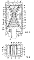
- FIGS. 4 to 6 show a cylinder which is primarily suitable as a clamping cylinder.
- the piston 2 'exerts a force when the interior 7 of the sleeve 3 is not acted upon by the pressure medium.
- the cylinder 1 ' which is again rectangular in cross section, has a side 8' and the walls 9 ', 10', 13 'and 14'.
- the piston 2 ' is guided between these walls.
- the sleeve 3 ' is arranged between the surfaces 11' and 12 'of the walls 9' and 10 '.
- On the side opposite the side 8 ', the sleeve 3' bears against a stop 23 fixed to the housing.
- a screw bolt 5 ' is screwed into this stop 23, which is firmly connected to the housing 1'.
- a return spring 4 ' is arranged between the bottom of the bore 19' and the head 20 'of the screw bolt 5'.
- Two spring assemblies 24, 25 are arranged between grooves 26 on the side 8 'and grooves 27 on the inside of the piston 2'. These spring assemblies 24, 25 consist of resilient flat springs, for example of rolled steel strip material. At rest, the springs are straight, as shown in FIG. 4. In the idle state, these spring assemblies 24, 25 bear against the cuff 3 'and against the stop 23.
- the piston 2 ' is suitable for pressing against any objects and thereby tightening them. If the objects clamped by the piston 2 'are to be released, then a pressure medium is passed into the interior 7' of the sleeve 3 ', whereby the piston 2' releases the object being held (FIG. 5).
- a piston 2 " is arranged to move back and forth inside the cylinder 1" which is rectangular in cross section.
- This piston 2 " has a piston rod 30 which is guided in a bore 31 at one end of the cylinder 1".
- a compression spring 4 " is arranged between this end of the cylinder 1 and the piston 2".
- Toggle joint mechanisms 32 are provided between the piston 2 "and the side 8" of the cylinder 1 ". These two toggle lever mechanisms 32 are supported on the one hand against grooves 27 'on the piston 2" and on the other hand in grooves 26' on the side 8 " Toggle joint mechanisms 32 each consist of a first lever 33 and a second lever 34, the knee joint being formed by a wedge-shaped incision on the lever 33, into which a rounding on the lever 34 engages.
- the collar 3 ′′ is arranged between the two joint mechanisms 32, the underside 8 ′′ and the cylinder-fixed stop 23 ′.
- This elastic sleeve 3 " which is annular in the idle state, has sealing lips 16" on the inside on its edges, which bear against the mutually parallel walls 11 “, 12" of the cylinder 1 ".
- the originally round sleeve 3" rests against the joint mechanisms 32, which are folded against the cuff 3 "in the idle state.
- the interior 7 “of the sleeve 3" is pressurized with the pressure medium via the connection 17 ", then the interior is enlarged Volume of the cuff 3 ". Since the cuff 3" lies against the stop 23 'and against the underside 8 ", the volume can only be increased in that the areas of the cuff 3" which bear against the joint mechanisms 32 are laterally outward move, the knee joint mechanisms 32 are converted into an elongated shape. As a result, the piston 2 "with its piston rod 30 is moved outward from the cylinder 1". If the cuff 3 "is relieved of pressure medium, then the spring 4" guides the piston 2 ", the lever mechanisms 32 and the cuff 3" back to the starting position shown.
- the stroke movement can be limited by stops 35 in the cylinder chamber, as a result of which the extension of the lever mechanisms 32 is limited.
- stops 35 can be adjustable. They are preferably set in such a way that complete extension is not achieved in order to ensure that the spring 4 "returns the lever mechanisms 32 to the starting position shown.
- the over-center position can be unlocked from outside by mechanical means or by applying pressure medium to the toggle lever parts from the outside or the like.
- the sleeve made of an elastic plastic material can have a jacket made of spring plate.
- the stop 23 'on the cylinder chamber side is not absolutely necessary.
- the cuff 3 "can rest there against the piston 2".
- the piston rod 30 exerts a relatively small stroke.
- the piston force is 10 to 15 times greater than a cylinder of the same size, in which the inside of the piston 2 "is acted upon directly by the pressure medium. This is achieved by the toggle lever mechanisms 32 arranged in the interior of the cylinder 1".
- FIGS. 9 and 10 differs from the embodiment variant described above primarily in that two arcuate springs 36 are used instead of the knee joint mechanisms 32.
- the sleeve 3 When pressure is applied to the working space 7 "of the sleeve 3", the sleeve 3 "is converted into an elongated shape, the piston 2" with its piston rod 30 executing a relatively small stroke with high force.
- the sleeve 3 is in contact with the piston 2".
- the cylinder can have only one lever mechanism 32 or 36, for example the right lever mechanism 32 in FIG. 7.
- embodiments are also conceivable in which the piston 2 executes a pivoting movement relative to the cylinder 1 and no axial movement.
- the piston 2 would not lead between the walls 13, 14, but z. B. via a hinge with one of these walls z. B. the wall 14 articulated.
- Either a spring assembly 24 or a flat spring 36 or a toggle lever mechanism 32 would have to be arranged between the sleeve 3 and the opposite wall 13 between the underside 8 of the cylinder 1 and the piston 2.
- the outer surface of the sleeve 3 is thus enclosed by the wall 14, the underside 8, the springs or the toggle lever mechanism and the piston 2.
- the piston 2 then leads due to the deformation of the springs 24 or 36 or Extension of the toggle mechanism 32 pivots around the hinge.
Landscapes
- Engineering & Computer Science (AREA)
- Mechanical Engineering (AREA)
- Physics & Mathematics (AREA)
- Fluid Mechanics (AREA)
- General Engineering & Computer Science (AREA)
- Actuator (AREA)
Claims (16)
Priority Applications (1)
| Application Number | Priority Date | Filing Date | Title |
|---|---|---|---|
| AT82109716T ATE17391T1 (de) | 1982-04-01 | 1982-10-21 | Druckmittelbetriebener stellantrieb. |
Applications Claiming Priority (4)
| Application Number | Priority Date | Filing Date | Title |
|---|---|---|---|
| DE3212155 | 1982-04-01 | ||
| DE3212155 | 1982-04-01 | ||
| DE3216753 | 1982-05-05 | ||
| DE19823216753 DE3216753A1 (de) | 1982-05-05 | 1982-05-05 | Vorrichtung zum erzeugen von druecken bei einem kolben |
Publications (2)
| Publication Number | Publication Date |
|---|---|
| EP0090885A1 EP0090885A1 (fr) | 1983-10-12 |
| EP0090885B1 true EP0090885B1 (fr) | 1986-01-08 |
Family
ID=25800859
Family Applications (1)
| Application Number | Title | Priority Date | Filing Date |
|---|---|---|---|
| EP82109716A Expired EP0090885B1 (fr) | 1982-04-01 | 1982-10-21 | Dispositif de manoeuvre à pression de fluide |
Country Status (6)
| Country | Link |
|---|---|
| US (2) | US4543877A (fr) |
| EP (1) | EP0090885B1 (fr) |
| JP (1) | JPS59500526A (fr) |
| AU (1) | AU1336583A (fr) |
| DE (1) | DE3268446D1 (fr) |
| WO (1) | WO1983003448A1 (fr) |
Families Citing this family (13)
| Publication number | Priority date | Publication date | Assignee | Title |
|---|---|---|---|---|
| DE3268446D1 (en) * | 1982-04-01 | 1986-02-20 | Sta Co Mettallerzeugnisse Gmbh | Fluid-pressure actuator |
| DE3638730A1 (de) * | 1986-11-13 | 1988-05-26 | Georg Roeck | Vorrichtung zum umsetzen, uebersetzen und uebertragen eines druckes |
| US4996981A (en) * | 1989-06-20 | 1991-03-05 | Allen Elenewski | Apparatus for removing condensate from a sealed face visor and for indicating a dangerous environmental temperature |
| FI894671A7 (fi) * | 1989-10-03 | 1991-04-04 | Erkki Rinne | Reglerbar faestanordning. |
| US5476268A (en) * | 1990-03-15 | 1995-12-19 | Unicraft Oy | Seal assembly with a hard seal layer actuated through a silicone layer |
| US5470083A (en) * | 1991-09-16 | 1995-11-28 | Unicraft Oy | Seal assembly with a hard seal layer actuated through a silicone layer |
| CA2115896A1 (fr) * | 1993-03-16 | 1994-09-17 | Edwin George Sawdon | Mecanisme generateur de force |
| GB9316126D0 (en) * | 1993-08-04 | 1993-09-22 | Gardiner Richard | A pneumatic ejector |
| GB2280713A (en) * | 1993-08-04 | 1995-02-08 | Richard Gardiner | A pneumatic ejector |
| EP1585616B1 (fr) * | 2003-01-20 | 2006-10-11 | Klaus Hofmann | Dispositif de serrage et/ou de freinage |
| DE10302225A1 (de) * | 2003-01-20 | 2004-07-29 | Innotech Engineering Gmbh | Klemm- und/oder Bremsvorrichtung |
| DE10335795A1 (de) * | 2003-08-05 | 2005-03-10 | Klaus Hofmann | Klemm- und/oder Bremsvorrichtung |
| JP6992712B2 (ja) * | 2018-09-07 | 2022-01-13 | トヨタ自動車株式会社 | ロボットアーム |
Family Cites Families (16)
| Publication number | Priority date | Publication date | Assignee | Title |
|---|---|---|---|---|
| US345446A (en) * | 1886-07-13 | powers | ||
| US2617260A (en) * | 1942-05-01 | 1952-11-11 | Baldwin Philip Sidney | Pressure amplifying system for hydraulic brake wheel cylinders |
| US2655943A (en) * | 1950-10-19 | 1953-10-20 | Dunlop Rubber Co | Hydrostatic apparatus |
| US2724411A (en) * | 1953-02-24 | 1955-11-22 | Ohio Commw Eng Co | Variable surge chamber and/or accumulator |
| GB772177A (en) * | 1953-12-02 | 1957-04-10 | Dunlop Rubber Co | Fluid pressure actuated system and operating means therefor |
| US2826420A (en) * | 1954-01-08 | 1958-03-11 | Karl A Klingler | Hydraulic holding means for chucks and the like |
| US3025072A (en) * | 1960-08-26 | 1962-03-13 | Specialties Inc | Clamping device |
| US3663027A (en) * | 1970-09-14 | 1972-05-16 | Ingersoll Milling Machine Co | Fluid actuated clamp |
| FR2105632A5 (fr) * | 1970-09-15 | 1972-04-28 | Hure Sa | |
| US3876255A (en) * | 1972-11-13 | 1975-04-08 | Ilon B E | Wheels for a course stable selfpropelling vehicle movable in any desired direction on the ground or some other base |
| US3815464A (en) * | 1973-01-17 | 1974-06-11 | Frost Eng Dev | Gas operated single stroke servo-motor |
| SU569764A1 (ru) * | 1973-12-20 | 1977-08-25 | Томский Ордена Октябрьской Революции И Ордена Трудового Красного Знамени Политехнический Институт Им.С.М.Кирова | Гидравлический (пневматический) исполнительный механизм |
| FR2278968A1 (fr) * | 1973-12-21 | 1976-02-13 | Mysliwiec Jean | Actionneur a mouvement angulaire alternatif |
| GB1604686A (en) * | 1978-05-31 | 1981-12-16 | Pilgrim Eng Dev | Fluid pressure actuators |
| FR2448060A1 (fr) * | 1979-02-02 | 1980-08-29 | Roeder & Spengler Stanz | Dispositif pour commander la course de travail de pieces en mouvement |
| DE3268446D1 (en) * | 1982-04-01 | 1986-02-20 | Sta Co Mettallerzeugnisse Gmbh | Fluid-pressure actuator |
-
1982
- 1982-10-21 DE DE8282109716T patent/DE3268446D1/de not_active Expired
- 1982-10-21 EP EP82109716A patent/EP0090885B1/fr not_active Expired
-
1983
- 1983-03-24 JP JP58501048A patent/JPS59500526A/ja active Pending
- 1983-03-24 AU AU13365/83A patent/AU1336583A/en not_active Abandoned
- 1983-03-24 WO PCT/DE1983/000055 patent/WO1983003448A1/fr not_active Ceased
- 1983-03-24 US US06/563,412 patent/US4543877A/en not_active Expired - Fee Related
-
1985
- 1985-06-03 US US06/740,693 patent/US4638724A/en not_active Expired - Fee Related
Also Published As
| Publication number | Publication date |
|---|---|
| DE3268446D1 (en) | 1986-02-20 |
| US4638724A (en) | 1987-01-27 |
| AU1336583A (en) | 1983-10-24 |
| WO1983003448A1 (fr) | 1983-10-13 |
| US4543877A (en) | 1985-10-01 |
| JPS59500526A (ja) | 1984-03-29 |
| EP0090885A1 (fr) | 1983-10-12 |
Similar Documents
| Publication | Publication Date | Title |
|---|---|---|
| EP0090885B1 (fr) | Dispositif de manoeuvre à pression de fluide | |
| DE2823584C2 (de) | Greifvorrichtung für Industrieroboter | |
| DE3153268C2 (en) | Two-cylinder viscous-material pump, preferably concrete pump | |
| DD282423A5 (de) | Einrichtung zum klemmen biegsamer druckplatten auf dem plattenzylinder einer rotationsdruckmaschine | |
| DE2242204C3 (de) | Druckmittelbeaufschlagter Servomotor | |
| DE2737327C2 (fr) | ||
| DE69411760T2 (de) | Durch elastische Verformung von Tellerfedern wirkende Bremse | |
| DE3502575A1 (de) | Kurzhub-spannelement | |
| DE1817816C3 (de) | Hydraulisch nachstellbare Führung. Ausscheidung aus: 1815638 | |
| DD249071A5 (de) | Kolbenstangenloser zylinder | |
| DE4000099A1 (de) | Vorrichtung zum aufspannen von werkstuecken mittels unterdruck | |
| DE29918229U1 (de) | Probenhalter zum Spannen von Werkstücken | |
| DE8511577U1 (de) | Kolbenstangenloser Zylinder | |
| DE69105009T2 (de) | Druckluftzylinder mit Verriegelungseinrichtung. | |
| DE69906199T2 (de) | Kolben-Zylinder-Stellglied für einen Schlittentisch | |
| DE2356075B2 (de) | Rollenkäfig für die Rollen einer Spreizkeil-Betätigungsvorrichtung für Innenbackenbremsen, insbesondere für Fahrzeuge | |
| EP0562503B1 (fr) | Vérin à air | |
| DD128820B1 (de) | Dreistellungszylinder fuer getriebefernschaltung | |
| EP0141106A2 (fr) | Cylindre de travail à trois positions | |
| DE2145643C3 (de) | Spannvorrichtung für Werkzeugmaschinen | |
| DE1680180C3 (de) | Bremsbetätigungsvorrichtung für Fahrzeuge | |
| EP0643228A1 (fr) | Dispositif pour bloquer une tige axialement mobile | |
| DE2366135C2 (de) | Spreizkeil-Betätigungsvorrichtung für Innenbackenbremsen | |
| DE2103868B2 (de) | Bolzensetzgerät | |
| WO2026068596A1 (fr) | Nouvelle partie boîtier pour un dispositif de serrage et/ou de freinage pneumatique |
Legal Events
| Date | Code | Title | Description |
|---|---|---|---|
| PUAI | Public reference made under article 153(3) epc to a published international application that has entered the european phase |
Free format text: ORIGINAL CODE: 0009012 |
|
| 17P | Request for examination filed |
Effective date: 19830806 |
|
| AK | Designated contracting states |
Designated state(s): AT BE CH DE FR GB IT LI NL SE |
|
| GRAA | (expected) grant |
Free format text: ORIGINAL CODE: 0009210 |
|
| AK | Designated contracting states |
Designated state(s): AT BE CH DE FR GB IT LI NL SE |
|
| REF | Corresponds to: |
Ref document number: 17391 Country of ref document: AT Date of ref document: 19860115 Kind code of ref document: T |
|
| ITF | It: translation for a ep patent filed | ||
| REF | Corresponds to: |
Ref document number: 3268446 Country of ref document: DE Date of ref document: 19860220 |
|
| ET | Fr: translation filed | ||
| PLBE | No opposition filed within time limit |
Free format text: ORIGINAL CODE: 0009261 |
|
| STAA | Information on the status of an ep patent application or granted ep patent |
Free format text: STATUS: NO OPPOSITION FILED WITHIN TIME LIMIT |
|
| 26N | No opposition filed | ||
| PGFP | Annual fee paid to national office [announced via postgrant information from national office to epo] |
Ref country code: AT Payment date: 19891020 Year of fee payment: 8 |
|
| PGFP | Annual fee paid to national office [announced via postgrant information from national office to epo] |
Ref country code: SE Payment date: 19891027 Year of fee payment: 8 |
|
| PGFP | Annual fee paid to national office [announced via postgrant information from national office to epo] |
Ref country code: NL Payment date: 19891031 Year of fee payment: 8 Ref country code: GB Payment date: 19891031 Year of fee payment: 8 |
|
| PG25 | Lapsed in a contracting state [announced via postgrant information from national office to epo] |
Ref country code: GB Effective date: 19901021 Ref country code: AT Effective date: 19901021 |
|
| PG25 | Lapsed in a contracting state [announced via postgrant information from national office to epo] |
Ref country code: SE Effective date: 19901022 |
|
| PG25 | Lapsed in a contracting state [announced via postgrant information from national office to epo] |
Ref country code: NL Effective date: 19910501 |
|
| NLV4 | Nl: lapsed or anulled due to non-payment of the annual fee | ||
| GBPC | Gb: european patent ceased through non-payment of renewal fee | ||
| ITTA | It: last paid annual fee | ||
| PGFP | Annual fee paid to national office [announced via postgrant information from national office to epo] |
Ref country code: CH Payment date: 19940128 Year of fee payment: 12 |
|
| PG25 | Lapsed in a contracting state [announced via postgrant information from national office to epo] |
Ref country code: LI Effective date: 19941031 Ref country code: CH Effective date: 19941031 |
|
| EUG | Se: european patent has lapsed |
Ref document number: 82109716.9 Effective date: 19910603 |
|
| REG | Reference to a national code |
Ref country code: CH Ref legal event code: PL |
|
| PGFP | Annual fee paid to national office [announced via postgrant information from national office to epo] |
Ref country code: FR Payment date: 19951031 Year of fee payment: 14 |
|
| PGFP | Annual fee paid to national office [announced via postgrant information from national office to epo] |
Ref country code: BE Payment date: 19951102 Year of fee payment: 14 |
|
| PG25 | Lapsed in a contracting state [announced via postgrant information from national office to epo] |
Ref country code: BE Effective date: 19961031 |
|
| BERE | Be: lapsed |
Owner name: DE-STA-CO METALLERZEUGNISSE G.M.B.H. Effective date: 19961031 |
|
| PG25 | Lapsed in a contracting state [announced via postgrant information from national office to epo] |
Ref country code: FR Effective date: 19970630 |
|
| REG | Reference to a national code |
Ref country code: FR Ref legal event code: ST |
|
| PGFP | Annual fee paid to national office [announced via postgrant information from national office to epo] |
Ref country code: DE Payment date: 20011212 Year of fee payment: 20 |