EP0090891B1 - Turbine - Google Patents
Turbine Download PDFInfo
- Publication number
- EP0090891B1 EP0090891B1 EP19820301754 EP82301754A EP0090891B1 EP 0090891 B1 EP0090891 B1 EP 0090891B1 EP 19820301754 EP19820301754 EP 19820301754 EP 82301754 A EP82301754 A EP 82301754A EP 0090891 B1 EP0090891 B1 EP 0090891B1
- Authority
- EP
- European Patent Office
- Prior art keywords
- rotor
- working fluid
- stage
- turbine
- buckets
- Prior art date
- Legal status (The legal status is an assumption and is not a legal conclusion. Google has not performed a legal analysis and makes no representation as to the accuracy of the status listed.)
- Expired
Links
- 239000012530 fluid Substances 0.000 claims description 70
- 238000011144 upstream manufacturing Methods 0.000 claims description 12
- 239000013598 vector Substances 0.000 claims description 3
- 230000009977 dual effect Effects 0.000 claims description 2
- 238000013461 design Methods 0.000 description 4
- 238000003801 milling Methods 0.000 description 4
- 239000002184 metal Substances 0.000 description 3
- 239000000203 mixture Substances 0.000 description 3
- 230000008901 benefit Effects 0.000 description 2
- 238000012546 transfer Methods 0.000 description 2
- 238000005266 casting Methods 0.000 description 1
- 238000004891 communication Methods 0.000 description 1
- 238000010276 construction Methods 0.000 description 1
- 230000008878 coupling Effects 0.000 description 1
- 238000010168 coupling process Methods 0.000 description 1
- 238000005859 coupling reaction Methods 0.000 description 1
- 238000012423 maintenance Methods 0.000 description 1
- 239000000463 material Substances 0.000 description 1
- 238000000034 method Methods 0.000 description 1
- 230000002093 peripheral effect Effects 0.000 description 1
- 230000008569 process Effects 0.000 description 1
- 230000004044 response Effects 0.000 description 1
- 230000035939 shock Effects 0.000 description 1
- 230000007480 spreading Effects 0.000 description 1
- 229910001220 stainless steel Inorganic materials 0.000 description 1
- 239000010935 stainless steel Substances 0.000 description 1
- 230000007704 transition Effects 0.000 description 1
Images


Classifications
-
- F—MECHANICAL ENGINEERING; LIGHTING; HEATING; WEAPONS; BLASTING
- F01—MACHINES OR ENGINES IN GENERAL; ENGINE PLANTS IN GENERAL; STEAM ENGINES
- F01D—NON-POSITIVE DISPLACEMENT MACHINES OR ENGINES, e.g. STEAM TURBINES
- F01D9/00—Stators
- F01D9/02—Nozzles; Nozzle boxes; Stator blades; Guide conduits, e.g. individual nozzles
- F01D9/04—Nozzles; Nozzle boxes; Stator blades; Guide conduits, e.g. individual nozzles forming ring or sector
- F01D9/045—Nozzles; Nozzle boxes; Stator blades; Guide conduits, e.g. individual nozzles forming ring or sector for radial flow machines or engines
-
- F—MECHANICAL ENGINEERING; LIGHTING; HEATING; WEAPONS; BLASTING
- F01—MACHINES OR ENGINES IN GENERAL; ENGINE PLANTS IN GENERAL; STEAM ENGINES
- F01D—NON-POSITIVE DISPLACEMENT MACHINES OR ENGINES, e.g. STEAM TURBINES
- F01D1/00—Non-positive-displacement machines or engines, e.g. steam turbines
- F01D1/02—Non-positive-displacement machines or engines, e.g. steam turbines with stationary working-fluid guiding means and bladed or like rotor, e.g. multi-bladed impulse steam turbines
- F01D1/026—Impact turbines with buckets, i.e. impulse turbines, e.g. Pelton turbines
-
- F—MECHANICAL ENGINEERING; LIGHTING; HEATING; WEAPONS; BLASTING
- F01—MACHINES OR ENGINES IN GENERAL; ENGINE PLANTS IN GENERAL; STEAM ENGINES
- F01D—NON-POSITIVE DISPLACEMENT MACHINES OR ENGINES, e.g. STEAM TURBINES
- F01D1/00—Non-positive-displacement machines or engines, e.g. steam turbines
- F01D1/02—Non-positive-displacement machines or engines, e.g. steam turbines with stationary working-fluid guiding means and bladed or like rotor, e.g. multi-bladed impulse steam turbines
- F01D1/16—Non-positive-displacement machines or engines, e.g. steam turbines with stationary working-fluid guiding means and bladed or like rotor, e.g. multi-bladed impulse steam turbines characterised by having both reaction stages and impulse stages
Definitions
- the invention relates to a dual pressure turbine, which is arranged to be driven by a working fluid such as steam, and of the kind (hereinafter referred to as of the kind described) comprising a high pressure section having at least one radial impulse turbine stage with a rotor; a low pressure section having at least one axial flow turbine stage with a rotor; means for connecting the rotors coaxially as a single rotary unit; means for introducing working fluid at one pressure into the high pressure section to drive the radial impulse stage; and means for introducing working fluid at a lower pressure into the low pressure section to drive the axial flow stage; the radial impulse stage rotor having buckets spaced around and opening at the periphery thereof, and a nozzle ring comprising an annular array of nozzles for introducing the higher pressure working fluid into the buckets to turn the rotor.
- a turbine of this kind is disclosed in GB-A-543098.
- the surfaces of the vanes, which define the outlets of the nozzles adjacent to the buckets are conventionally flat, as exemplified in GB-A-543098, US-A-1896809 and US-A-4150918, and the edges of the vanes adjacent to the buckets usually include a wedge angle of 11° or more.
- the nozzle ring has vanes separating and defining the contours of adjacent nozzles; the vanes having surfaces which face the axis of the rotor and which are continuously curved from their edges at the nozzle outlets to their portions lying radially outwardly of the edges of the adjacent vanes; and the edge of each vane presenting an included wedge angle of not more than 3°.
- the curvature of the vane surfaces is similar to that of the outer periphery of the rotor.
- the turbine may have means for combining working fluid exhausted from the high pressure section with further working fluid to provide the lower pressure working fluid to be introduced into the low pressure section.
- steam discharged from the high pressure section may combine with steam supplied to the turbine at low pressure, the mixture being delivered to the low pressure turbine stage. Maximum utilization of available energy is promoted by this arrangement.
- the turbine may have a single inlet, this inlet communicating with the or the first of the radial impulse stages; whereby the working fluid discharged from the or the last of the radial impulse stages is transferred to the or the first axial flow stage to provide the whole of the working fluid which is supplied to the low pressure section.
- a turbine of this construction is of the "once-through" type. Thus all of the working fluid is supplied to the turbine at one pressure, and the working fluid is discharged directly from the radial impulse staging into the first of the axial flow stages. At some sacrifice in efficiency, this design reduces complexity, lowers maintenance costs, and increases reliability; and it has a faster response time. Consequently this one-through arrangement may prove superior in applications, such as naval shipboard use, where the advantages identified above take precedence over efficiency.
- connection of the rotors of each of the radial impulse and axial flow stages coaxially as a single rotary unit eliminates the need for gearing between the high and low. pressure sections along with the associated expense and power loss. In this case there will usually be a common casing containing both the high and low pressure sections.
- Certain valuable features may be incorporated in the, or at least one radial impulse stage, particularly to accommodate higher than conventional working fluid velocities.
- each of the buckets has an entrance at one side of the rotor and an exit at the other side of the rotor, and the bucket is so shaped that the flow vectors of the fluid entering and exiting from the bucket, in use, are substantially parallel to one another and to planes perpendicular to the axis of the rotor. This leads to significantly greater efficiency than in conventional flow designs.
- efficiency is promoted if the cross sections of the buckets and of the nozzle outlets, perpendicular to the flow of working fluid, have substantially right angular corners. This arrangement effectively reduces unwanted power-wasting shock and turbulence.
- the rotor is completely shrouded between entrances and exits of the buckets by a surrounding shroud to maximize the work available from the working fluid; and the nozzle ring abuts an upstream face of the shroud whereby the shroud provides the downstream walls of the nozzles.
- the shrouding I keeps the character of the flow, the circulation of which is otherwise of generally unspecified character, constant adjacent to the buckets. This eliminates the windage loss that occurs in conventional, unshrouded or partially shrouded radial impulse turbines.
- the high pressure section may include first and second radial impulse stages each with one of the rotors and one of the nozzle rings; each of the nozzles having an inlet opening at the outer periphery of the ring and an outlet opening at the inner periphery of the ring; and flow directing means for turning working fluid discharged radially outwardly from the buckets of the first stage rotor axially towards the second stage rotor and then radially inwardly into the inlets of the nozzles of the second stage nozzle ring.
- the high pressure section also includes a discharge plenum on the downstream side of the rotor of the, or the most downstream, radial impulse stage, the bucket of which rotor being so shaped as to dump the working fluid into the discharge plenum after that fluid has passed once through the buckets of that rotor.
- the turbine 6 of Figures 1 to 4 includes an elongate, external casing 7 which has a generally circular cross-section and is made up of a number of bolted-together casing components.
- the interior of the casing 7 is divided into a high pressure section 8 and a low pressure section 9 (see Figures 2 and 3).
- the high pressure section 8 has two impulse turbine stages 10 and 11; the low pressure section 9 has six conventional, axial flow turbine stages 12, 13, 14, 15, 16 and 17.
- Each of the high and low pressure turbine stages includes a rotor which is identifed by the same reference character as the stage but followed by the letter R.
- the eight rotors 10R...17R are coupled together with splines (assembled fittings are shown diagrammatically in Figure 3 and identified by reference character 18).
- the components of the resulting assembly are held together by a single tension bolt 19, and the assembly is rotatably supported in the casing 8 by appropriate bearings (not shown).
- the upstream (or front) end of the assembly is splined to accept a drive coupling (the splines are not shown), and provide a power take-off upstream of the high pressure section.
- the first and second stage rotors 10R and 11R in the high pressure section 8 of the turbine 6 are cast from 17-4PH stainless steel or a comparable material for steam service.
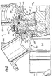
- the first stage rotor 10R is surrounded by an annular nozzle ring 20 of which nozzles 21 are of the convergent configuration illustrated in Figure 4.
- the nozzles are defined between vanes 21A formed by metal left in the process of milling the ring 22 to form the nozzles.
- the vanes have sharp edges 21C, presenting a wedge angle of up to 3°, and curved surfaces 21B which face radially inwardly towards the axis of the rotor and extend from the edges 21C to positions overlying the edges 21 C of the next vane.
- the curvature of the surfaces 21 B is similar to, i.e. within ⁇ 10% of, that of the outer periphery of the rotor.
- Each nozzle has an inlet 22 opening onto the outer periphery of the nozzle ring and an outlet 23 opening onto its inner periphery, and they are of square cross section perpendicular to the fluid flow at their discharge ends.
- the outlets of the nozzles 21 are radially aligned with entrances 24 to buckets 25 in a peripheral flange 26 of the first stage rotor 10R as shown in Figure 2.
- buckets are equiangularly spaced and they are typically formed by milling with the cutter inclined at an angle of 18° to the radial.
- the buckets 25 have a section perpendicular to the fluid flow with substantially right angular corners 27 (see Figure 4), an entrance 24 adjacent to the upstream side of the rotor, an exit 28 adjacent to the downstream side of the rotor and a part circular impulse surface 29 between the entrance and the exit.
- a groove is milled in the rotor before the buckets 25 are milled. This groove extends continuously around, and opens into, the periphery of the rotor and generates slots in the eventual leading edges of the buckets.
- the groove is primarily provided to accommodate the shank of a cutter used to form the buckets, but also eliminates excess metal from the rotor and lowers rotor and bucket stresses.
- the outlets 23 of the nozzles 21 form an almost continuous circle around the rotor 10R. This, together with the sharp edge between adjacent buckets provides essentially full arc admission of working fluid to the buckets and ensures that the buckets are smoothly filled. That contributes significantly to the efficiency of the turbine.
- the nozzle ring 20 is coupled by an antirotation pin 31 to a radial flange 32 at the downstream end of an annular, high pressure inlet manifold 33.
- the manifold is bolted between casing components 34 and 35 on the upstream side of high pressure section first stage rotor 10R.
- the nozzle ring 20 is clamped against the flange 32, and the downstream walls of the nozzles 21 are formed, by a plate-like inner shroud 36 of the casing component 35.
- the latter is bolted between the manifold 33 and an outer casing component 37.
- Working fluid is supplied to the first stage 10 of the turbine 6 through an inlet 38 which communicates with the interior of the high pressure inlet manifold 33.
- the working fluid flows axially from the manifold through an annular inlet 39 between the outer periphery of the nozzle ring 20 and the inner wall of the manifold 33. It then flows radially inwards into the nozzles 21 in the nozzle ring 20 as shown by arrow 40 in Figure 2.
- the working fluid is discharged from the nozzles into the buckets 25 of the rotor 10R, flowing through the latter to drive the rotor. It then flows radially outwards as indicated by arrow 41.
- the entrance and exit flow vectors of the working fluid are parallel.
- Efficiency is also promoted by completely shrouding the buckets 25 between their entrances 24 and exits 28 by the shroud 36, which completely surrounds the rotor 10R. This complete shrouding minimizes power-robbing turbulence. It also promotes efficiency by maintaining a free surface on the exit side of each bucket. Furthermore, because the exiting working fluid does not impinge on the shrould 36, its exit momentum is preserved. This is an attribute of particular importance in multi-stage turbines.
- the outwardly flowing working fluid discharged from the buckets of the rotor 10R is turned first axially and then radially inwards (see arrow 42) by the cooperation between the casing component 37 and an annular, disc-like flow director 43.
- the latter is fixed to the upstream side of a radially and inwardly extending annular flange 44 on the casing component 37 by screw threaded fasteners 45.
- the workingfluid discharged from the first stage 10 flows into nozzles 48 formed in a nozzle ring 49 surrounding the second stage rotor 11R. Again, the nozzle outlets are aligned with entrances 50 to buckets 51 which are similar to the buckets 25.
- the nozzle ring 49 is seated in a recess 52 in the flow director 43 and is clamped against the upstream side of the flange 44 by the flow director and the fasteners 45.
- the upstream face of the flange forms the rear or downstream walls of the nozzles.
- the nozzles 48 will preferably be of a convergent configuration like that shown in Figure 4.
- the second stage rotor 11 R is, like that discussed previously, completely shrouded.
- the shrouding is effected by the circular, radially oriented flange 44 on the casing component 37.
- the working fluid After passing through the buckets 51 of the second stage turbine rotor 10R, the working fluid is discharged radially outwards from the buckets through exits 53 into an annular plenum 54 located between the high and low pressure turbine sections 8 and 9.
- the working fluid discharged from the high pressure section of the turbine is combined with working fluid introduced to the turbine through an inlet 55 and an annular low pressure inlet manifold 56 surrounding the plenum 54.
- Communication between the manifold and the plenum 54 is effected by an inwardly directed, circular opening 57.
- the nozzle is defined by axially extending, circular bosses 58 and 59, which are integral parts of the casing component 37, and by the manifold 56 and the inlet 55.
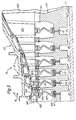
- the working fluid mixture flows axially as indicated by arrow 60 in Figures 2 and 3 into the low pressure section 9 of the turbine 6. That section of the turbine 6 (which is of conventional axial flow design) is best shown in Figure 3.
- Each turbine stage in the low pressure section includes one of the previously mentioned rotors, composed of a disc 61 to which an annular array of blades 62 is attached. Upstream from each rotor is a conventional annular array of stationary nozzles 63. The nozzles of each stage are attached to an annular nozzle support 64 which is fixed to the casing component 37.
- An axially extending, circularflange 68 is fixed to the diaphragm 65 of the first axial flow stage 12 to guide the working fluid mixture from the annular exhaust plenum 54 into the nozzles 63 of the first axial turbine stage.
- each of the low pressure, axial flow stages preferably includes an annular, abradable rub ring 69 which is part of the nozzle support of that stage and surrounds its rotor.
- These rub rings allow minimum tip clearance for the working fluid to be employed, lowering leakage of the working fluid past the blade tips.
- Flow of the working fluid through the low pressure section is conventional with the working fluid being discharged from the blades 62 of the sixth stage rotor 17R into an annular exhaust manifold (not shown). The working fluid is discharged from this manifold and the turbine casing through an exhaust duct 70 (see Figure 1).
- this turbine will be supplied with high pressure steam at 13.7x10 5 Pa (200 psia) and 382°C (720°F) at a rate of 1.47 kg/s (3.23 lbs/second) and with low pressure steam at 2.76x10 5 Pa (40 psia) and 421°C (790°F) at 0.35 kg/s (0.76 lbs/ second).
- the design pressure of the steam exhausted from the last stage of the low pressure, axial flow section of the turbine is 4.48x10 3 Pa (0.65 psia).
- the rotors of the two impulse stages 10 and 11 in the high pressure section 8 of the turbine 6 are, respectively, 0.30 and 0.35 m (11.75 and 13.875 inches) in diameter; and the mid-chord lengths of the blades 62 in the low pressure axial flow section of the turbine range from 0.015 m (0.6 inch) in the first stage 12 to 0.13 m (5.16 inches) in the sixth stage 17.
- the discs on which the blades are mounted are all 0.34 m (13.5 inches) in diameter.
- the invention may also be applied to a once-through turbine having a combination of radial impulse and axial flow stages.
- a turbine of this type which also includes a more efficient arrangement for transferring working fluid from one radial impulse stage to the next and which demonstrates that more than two radial impulse stages can be employed, is shown at 71 in Figure 5.
- the turbine 71 is similar to the previously described example. Consequently, and for the sake of clarity and conciseness, the turbine 71 will be described primarily in reference to those features which distinguish it from the previously described turbine.
- the turbine 71 includes an elongate, external casing 72 housing three radial impulse stages 73, 74, and 75 and seven axial flow stages 76...(only one of which is shown).
- Each of the axial flow stages (which can be of the character described above in conjunction with the turbine 6) and each of the impulse turbine stages includes a rotor which is identified by the same reference character as the stage but followed by the letter R.
- the ten rotors 73R...76R are coupled together by Curvic fittings 77 and held in assembled relationship by a tension bolt 78.
- Appropriate bearings (not shown) rotatably support the resulting assembly in the casing 72.
- the rotors 73R, 74R, and 75R of the radial impulse stages may be like those employed in the turbine 6; and they are surrounded by shrouds 79, 80, and 81 to obtain those above discussed benefits which complete shrouding is capable of providing.
- the first stage rotor 73R is surrounded by an annular nozzle ring 82 with nozzles of the type illustrated in Figure 4.
- the nozzle ring 82 is clamped between the shroud 79 and a working fluid inlet manifold 83.
- Working fluid is supplied to the first stage 73 of the turbine 71 through a working fluid inlet 84 which communicates with the interior of inlet manifold 83.
- the working fluid flows from the manifold through an annular inlet 85 into the nozzles in the nozzle ring.
- the working fluid is discharged from the nozzles into the buckets of the rotor 73R, flowing through the latter to drive the rotor.
- the outwardly flowing working fluid discharged from the buckets of the rotor 73R is turned first axially and then radially inward by the cooperation between the turbine casing 72 and a flow director 86.
- the latter is similar to the flow directors employed in the turbine 6 shown in Figure 2. This keeps the stream of working fluid exiting from the buckets from spreading as it is directed from the first stage rotor 73R to a nozzle ring 87 in the second radial impulse stage 74. That is important in that it minimizes energy losses as the transfer of fluid is affected.
- Flow of the working fluid through the axial flow stage is conventional with the working fluid being discharged from the last stage rotor into an annular exhaust manifold (not shown).
- the working fluid is discharged from this manifold and the turbine casing through an exhaust duct similar to that shown in Figure 1.
Landscapes
- Engineering & Computer Science (AREA)
- Mechanical Engineering (AREA)
- General Engineering & Computer Science (AREA)
- Turbine Rotor Nozzle Sealing (AREA)
Claims (12)
Priority Applications (2)
| Application Number | Priority Date | Filing Date | Title |
|---|---|---|---|
| DE8282301754T DE3276585D1 (en) | 1982-04-02 | 1982-04-02 | Turbine |
| EP19820301754 EP0090891B1 (de) | 1982-04-02 | 1982-04-02 | Turbine |
Applications Claiming Priority (1)
| Application Number | Priority Date | Filing Date | Title |
|---|---|---|---|
| EP19820301754 EP0090891B1 (de) | 1982-04-02 | 1982-04-02 | Turbine |
Publications (2)
| Publication Number | Publication Date |
|---|---|
| EP0090891A1 EP0090891A1 (de) | 1983-10-12 |
| EP0090891B1 true EP0090891B1 (de) | 1987-06-16 |
Family
ID=8189630
Family Applications (1)
| Application Number | Title | Priority Date | Filing Date |
|---|---|---|---|
| EP19820301754 Expired EP0090891B1 (de) | 1982-04-02 | 1982-04-02 | Turbine |
Country Status (2)
| Country | Link |
|---|---|
| EP (1) | EP0090891B1 (de) |
| DE (1) | DE3276585D1 (de) |
Family Cites Families (10)
| Publication number | Priority date | Publication date | Assignee | Title |
|---|---|---|---|---|
| FR340306A (fr) * | 1903-07-03 | 1904-07-02 | George Westinghouse | Perfectionnements dans les turbines à fluide sous pression |
| FR451838A (fr) * | 1912-02-19 | 1913-04-29 | Joseph Weishaeupl | Dispositif pour introduire un agent moteur additionnel à des étages intermédiaires des turbines à vapeur ou à gaz |
| US1803223A (en) * | 1927-11-07 | 1931-04-28 | Wagner Rudolf | Blading for steam and gas turbines |
| US1896809A (en) * | 1930-03-03 | 1933-02-07 | B F Sturtevant Co | Multistage turbine |
| DE580985C (de) * | 1930-04-10 | 1933-07-19 | Siemens Schuckertwerke Akt Ges | Radialbeaufschlagte Doppelfluss-UEberdruckturbine mit feststehender Leitvorrichtung |
| FR717126A (fr) * | 1930-05-17 | 1932-01-04 | Siemens Ag | Turbine à réaction en forme de turbine à tambour |
| FR817889A (fr) * | 1936-02-17 | 1937-09-13 | Siemens Ag | Turbine à une seule enveloppe |
| GB543098A (en) * | 1940-08-07 | 1942-02-10 | Leslie Wilson Downward | Improvements in or relating to turbines |
| DE759486C (de) * | 1941-05-04 | 1953-03-09 | Siemens Schuckertwerke A G | Fuer hohe Druecke und Temperaturen bestimmte Dampf- oder Gasturbine |
| US4150918A (en) * | 1976-01-21 | 1979-04-24 | Hollymatic Corporation | Pressure gas engine |
-
1982
- 1982-04-02 DE DE8282301754T patent/DE3276585D1/de not_active Expired
- 1982-04-02 EP EP19820301754 patent/EP0090891B1/de not_active Expired
Also Published As
| Publication number | Publication date |
|---|---|
| DE3276585D1 (en) | 1987-07-23 |
| EP0090891A1 (de) | 1983-10-12 |
Similar Documents
| Publication | Publication Date | Title |
|---|---|---|
| US7665964B2 (en) | Turbine | |
| US4882902A (en) | Turbine cooling air transferring apparatus | |
| US7354241B2 (en) | Rotor assembly with cooling air deflectors and method | |
| JP2640783B2 (ja) | 改良型の冷却用流体エジェクタ | |
| US5238364A (en) | Shroud ring for an axial flow turbine | |
| US4455121A (en) | Rotating turbine stator | |
| GB2245312A (en) | Axial flow compressor surge margin improvement | |
| GB1602235A (en) | Crossover duct | |
| JPH079194B2 (ja) | ガスタービン・エンジンの冷却空気転送手段 | |
| GB2081392A (en) | Turbomachine seal | |
| GB2260787A (en) | Cooling air stator to rotor flow inducer in gas turbine engines | |
| US4435121A (en) | Turbines | |
| US4571937A (en) | Apparatus for controlling the flow of leakage and cooling air of a rotor of a multi-stage turbine | |
| US4421454A (en) | Turbines | |
| US5097660A (en) | Coanda effect turbine nozzle vane cooling | |
| GB1602939A (en) | Crossover duct assembly primarily for multi-stage compressors | |
| CA2927035C (en) | Rotor assembly with wear member | |
| EP0097608B1 (de) | Turbinenrad mit in der Peripherie eingearbeiteten Schaufeln | |
| US9957807B2 (en) | Rotor assembly with scoop | |
| GB2057573A (en) | Turbine rotor assembly | |
| EP0814233B1 (de) | Rotorscheibe für eine Turbomaschine mit Leitungen zur Führung einer Kühlflüssigkeit | |
| US3582230A (en) | Turbomachine with cooled rotor | |
| EP0090891B1 (de) | Turbine | |
| GB2095764A (en) | Turbine arrangement | |
| CA1189796A (en) | Turbines |
Legal Events
| Date | Code | Title | Description |
|---|---|---|---|
| PUAI | Public reference made under article 153(3) epc to a published international application that has entered the european phase |
Free format text: ORIGINAL CODE: 0009012 |
|
| 17P | Request for examination filed |
Effective date: 19820505 |
|
| AK | Designated contracting states |
Designated state(s): CH DE GB LI SE |
|
| GRAA | (expected) grant |
Free format text: ORIGINAL CODE: 0009210 |
|
| AK | Designated contracting states |
Kind code of ref document: B1 Designated state(s): CH DE GB LI SE |
|
| REF | Corresponds to: |
Ref document number: 3276585 Country of ref document: DE Date of ref document: 19870723 |
|
| PLBE | No opposition filed within time limit |
Free format text: ORIGINAL CODE: 0009261 |
|
| STAA | Information on the status of an ep patent application or granted ep patent |
Free format text: STATUS: NO OPPOSITION FILED WITHIN TIME LIMIT |
|
| 26N | No opposition filed | ||
| PGFP | Annual fee paid to national office [announced via postgrant information from national office to epo] |
Ref country code: GB Payment date: 19940307 Year of fee payment: 13 |
|
| PGFP | Annual fee paid to national office [announced via postgrant information from national office to epo] |
Ref country code: SE Payment date: 19940317 Year of fee payment: 13 |
|
| PGFP | Annual fee paid to national office [announced via postgrant information from national office to epo] |
Ref country code: DE Payment date: 19940329 Year of fee payment: 13 |
|
| PGFP | Annual fee paid to national office [announced via postgrant information from national office to epo] |
Ref country code: CH Payment date: 19940718 Year of fee payment: 13 |
|
| EAL | Se: european patent in force in sweden |
Ref document number: 82301754.6 |
|
| PG25 | Lapsed in a contracting state [announced via postgrant information from national office to epo] |
Ref country code: GB Effective date: 19950402 |
|
| PG25 | Lapsed in a contracting state [announced via postgrant information from national office to epo] |
Ref country code: SE Effective date: 19950403 |
|
| PG25 | Lapsed in a contracting state [announced via postgrant information from national office to epo] |
Ref country code: LI Effective date: 19950430 Ref country code: CH Effective date: 19950430 |
|
| GBPC | Gb: european patent ceased through non-payment of renewal fee |
Effective date: 19950402 |
|
| REG | Reference to a national code |
Ref country code: CH Ref legal event code: PL |
|
| PG25 | Lapsed in a contracting state [announced via postgrant information from national office to epo] |
Ref country code: DE Effective date: 19960103 |
|
| EUG | Se: european patent has lapsed |
Ref document number: 82301754.6 |