EP0090933A2 - Appareil et méthode pour perforer ou perforer et couper des tubes - Google Patents
Appareil et méthode pour perforer ou perforer et couper des tubes Download PDFInfo
- Publication number
- EP0090933A2 EP0090933A2 EP83101558A EP83101558A EP0090933A2 EP 0090933 A2 EP0090933 A2 EP 0090933A2 EP 83101558 A EP83101558 A EP 83101558A EP 83101558 A EP83101558 A EP 83101558A EP 0090933 A2 EP0090933 A2 EP 0090933A2
- Authority
- EP
- European Patent Office
- Prior art keywords
- needle
- workpiece
- needles
- perforated
- perforating
- Prior art date
- Legal status (The legal status is an assumption and is not a legal conclusion. Google has not performed a legal analysis and makes no representation as to the accuracy of the status listed.)
- Granted
Links
Images


Classifications
-
- B—PERFORMING OPERATIONS; TRANSPORTING
- B26—HAND CUTTING TOOLS; CUTTING; SEVERING
- B26F—PERFORATING; PUNCHING; CUTTING-OUT; STAMPING-OUT; SEVERING BY MEANS OTHER THAN CUTTING
- B26F1/00—Perforating; Punching; Cutting-out; Stamping-out; Apparatus therefor
- B26F1/26—Perforating by non-mechanical means, e.g. by fluid jet
-
- B—PERFORMING OPERATIONS; TRANSPORTING
- B26—HAND CUTTING TOOLS; CUTTING; SEVERING
- B26D—CUTTING; DETAILS COMMON TO MACHINES FOR PERFORATING, PUNCHING, CUTTING-OUT, STAMPING-OUT OR SEVERING
- B26D3/00—Cutting work characterised by the nature of the cut made; Apparatus therefor
- B26D3/16—Cutting rods or tubes transversely
- B26D3/161—Cutting rods or tubes transversely for obtaining more than one product at a time
-
- B—PERFORMING OPERATIONS; TRANSPORTING
- B26—HAND CUTTING TOOLS; CUTTING; SEVERING
- B26F—PERFORATING; PUNCHING; CUTTING-OUT; STAMPING-OUT; SEVERING BY MEANS OTHER THAN CUTTING
- B26F1/00—Perforating; Punching; Cutting-out; Stamping-out; Apparatus therefor
- B26F1/0015—Perforating; Punching; Cutting-out; Stamping-out; Apparatus therefor specially adapted for perforating tubes
-
- B—PERFORMING OPERATIONS; TRANSPORTING
- B26—HAND CUTTING TOOLS; CUTTING; SEVERING
- B26F—PERFORATING; PUNCHING; CUTTING-OUT; STAMPING-OUT; SEVERING BY MEANS OTHER THAN CUTTING
- B26F1/00—Perforating; Punching; Cutting-out; Stamping-out; Apparatus therefor
- B26F1/24—Perforating by needles or pins
-
- B—PERFORMING OPERATIONS; TRANSPORTING
- B65—CONVEYING; PACKING; STORING; HANDLING THIN OR FILAMENTARY MATERIAL
- B65H—HANDLING THIN OR FILAMENTARY MATERIAL, e.g. SHEETS, WEBS, CABLES
- B65H75/00—Storing webs, tapes, or filamentary material, e.g. on reels
- B65H75/50—Methods of making reels, bobbins, cop tubes, or the like by working an unspecified material, or several materials
-
- B—PERFORMING OPERATIONS; TRANSPORTING
- B65—CONVEYING; PACKING; STORING; HANDLING THIN OR FILAMENTARY MATERIAL
- B65H—HANDLING THIN OR FILAMENTARY MATERIAL, e.g. SHEETS, WEBS, CABLES
- B65H2701/00—Handled material; Storage means
- B65H2701/30—Handled filamentary material
- B65H2701/31—Textiles threads or artificial strands of filaments
-
- Y—GENERAL TAGGING OF NEW TECHNOLOGICAL DEVELOPMENTS; GENERAL TAGGING OF CROSS-SECTIONAL TECHNOLOGIES SPANNING OVER SEVERAL SECTIONS OF THE IPC; TECHNICAL SUBJECTS COVERED BY FORMER USPC CROSS-REFERENCE ART COLLECTIONS [XRACs] AND DIGESTS
- Y10—TECHNICAL SUBJECTS COVERED BY FORMER USPC
- Y10S—TECHNICAL SUBJECTS COVERED BY FORMER USPC CROSS-REFERENCE ART COLLECTIONS [XRACs] AND DIGESTS
- Y10S493/00—Manufacturing container or tube from paper; or other manufacturing from a sheet or web
- Y10S493/954—Spool
-
- Y—GENERAL TAGGING OF NEW TECHNOLOGICAL DEVELOPMENTS; GENERAL TAGGING OF CROSS-SECTIONAL TECHNOLOGIES SPANNING OVER SEVERAL SECTIONS OF THE IPC; TECHNICAL SUBJECTS COVERED BY FORMER USPC CROSS-REFERENCE ART COLLECTIONS [XRACs] AND DIGESTS
- Y10—TECHNICAL SUBJECTS COVERED BY FORMER USPC
- Y10T—TECHNICAL SUBJECTS COVERED BY FORMER US CLASSIFICATION
- Y10T82/00—Turning
- Y10T82/16—Severing or cut-off
- Y10T82/16016—Processes
-
- Y—GENERAL TAGGING OF NEW TECHNOLOGICAL DEVELOPMENTS; GENERAL TAGGING OF CROSS-SECTIONAL TECHNOLOGIES SPANNING OVER SEVERAL SECTIONS OF THE IPC; TECHNICAL SUBJECTS COVERED BY FORMER USPC CROSS-REFERENCE ART COLLECTIONS [XRACs] AND DIGESTS
- Y10—TECHNICAL SUBJECTS COVERED BY FORMER USPC
- Y10T—TECHNICAL SUBJECTS COVERED BY FORMER US CLASSIFICATION
- Y10T82/00—Turning
- Y10T82/16—Severing or cut-off
- Y10T82/16426—Infeed means
- Y10T82/16803—Rotatable tool[s] driven by contact with work
- Y10T82/16819—Axially movable tool support
- Y10T82/16836—Freely floating parallel to axis
- Y10T82/16852—Freely floating parallel to axis with supplemental nonrotative tool
-
- Y—GENERAL TAGGING OF NEW TECHNOLOGICAL DEVELOPMENTS; GENERAL TAGGING OF CROSS-SECTIONAL TECHNOLOGIES SPANNING OVER SEVERAL SECTIONS OF THE IPC; TECHNICAL SUBJECTS COVERED BY FORMER USPC CROSS-REFERENCE ART COLLECTIONS [XRACs] AND DIGESTS
- Y10—TECHNICAL SUBJECTS COVERED BY FORMER USPC
- Y10T—TECHNICAL SUBJECTS COVERED BY FORMER US CLASSIFICATION
- Y10T82/00—Turning
- Y10T82/16—Severing or cut-off
- Y10T82/16426—Infeed means
- Y10T82/16967—Infeed means with means to support and/or rotate work
-
- Y—GENERAL TAGGING OF NEW TECHNOLOGICAL DEVELOPMENTS; GENERAL TAGGING OF CROSS-SECTIONAL TECHNOLOGIES SPANNING OVER SEVERAL SECTIONS OF THE IPC; TECHNICAL SUBJECTS COVERED BY FORMER USPC CROSS-REFERENCE ART COLLECTIONS [XRACs] AND DIGESTS
- Y10—TECHNICAL SUBJECTS COVERED BY FORMER USPC
- Y10T—TECHNICAL SUBJECTS COVERED BY FORMER US CLASSIFICATION
- Y10T83/00—Cutting
- Y10T83/04—Processes
- Y10T83/0405—With preparatory or simultaneous ancillary treatment of work
- Y10T83/041—By heating or cooling
- Y10T83/0414—At localized area [e.g., line of separation]
-
- Y—GENERAL TAGGING OF NEW TECHNOLOGICAL DEVELOPMENTS; GENERAL TAGGING OF CROSS-SECTIONAL TECHNOLOGIES SPANNING OVER SEVERAL SECTIONS OF THE IPC; TECHNICAL SUBJECTS COVERED BY FORMER USPC CROSS-REFERENCE ART COLLECTIONS [XRACs] AND DIGESTS
- Y10—TECHNICAL SUBJECTS COVERED BY FORMER USPC
- Y10T—TECHNICAL SUBJECTS COVERED BY FORMER US CLASSIFICATION
- Y10T83/00—Cutting
- Y10T83/04—Processes
- Y10T83/0448—With subsequent handling [i.e., of product]
- Y10T83/0453—By fluid application
-
- Y—GENERAL TAGGING OF NEW TECHNOLOGICAL DEVELOPMENTS; GENERAL TAGGING OF CROSS-SECTIONAL TECHNOLOGIES SPANNING OVER SEVERAL SECTIONS OF THE IPC; TECHNICAL SUBJECTS COVERED BY FORMER USPC CROSS-REFERENCE ART COLLECTIONS [XRACs] AND DIGESTS
- Y10—TECHNICAL SUBJECTS COVERED BY FORMER USPC
- Y10T—TECHNICAL SUBJECTS COVERED BY FORMER US CLASSIFICATION
- Y10T83/00—Cutting
- Y10T83/929—Tool or tool with support
- Y10T83/9314—Pointed perforators
-
- Y—GENERAL TAGGING OF NEW TECHNOLOGICAL DEVELOPMENTS; GENERAL TAGGING OF CROSS-SECTIONAL TECHNOLOGIES SPANNING OVER SEVERAL SECTIONS OF THE IPC; TECHNICAL SUBJECTS COVERED BY FORMER USPC CROSS-REFERENCE ART COLLECTIONS [XRACs] AND DIGESTS
- Y10—TECHNICAL SUBJECTS COVERED BY FORMER USPC
- Y10T—TECHNICAL SUBJECTS COVERED BY FORMER US CLASSIFICATION
- Y10T83/00—Cutting
- Y10T83/929—Tool or tool with support
- Y10T83/9372—Rotatable type
- Y10T83/9382—Punching plus nonpunching tool
Definitions
- the invention relates to a method for perforating and / or cutting concentric or rotationally symmetrical hollow body on the wall, in particular of winding carriers such.
- a rotationally symmetrical textile sleeve made of thermoplastic material is known, which is deformable in the radial and also in the axial direction.
- the textile winding can be subjected to a wet and / or heat treatment, perforations being provided in the wall of the textile sleeve for the permeability of the liquor.
- the primary object of the invention is to provide a method with which sleeves can be perforated quickly and economically in a simple manner and / or, if necessary, cut to their correct length.
- a method for perforating the type mentioned above is characterized above all by repeatedly stabbing at the points of the workpiece to be perforated with one or more needles, stamps, pins or the like, and in that the punctures are carried out as often and so can be repeated quickly in succession that the needle tips or the like, which plunge into the perforations several times, heat themselves due to friction.
- the invention makes use of the frictional heat generated during piercing and repeated dipping into a perforation in order to make an initially small perforation into a perforation.
- the hollow body to be perforated has been rotated during the perforation and if at least one rotating body, which is also equipped with needles or the like and is also rotated, is set in counter-rotation, the circumferential circle running through the needle tips or the like into the surface of the immersed body to be perforated and the speed is selected so that the needle tips or the like repeatedly immersed in the same places are heated by friction.
- the rotating body to be perforated can be rotated or the like by the rotation of the needle carrier or carriers and the temporary positive locking of the needles piercing it. It is therefore sufficient if only at least one of the needle carriers is provided with a drive.
- the self-heating needles or the like can be blown to adjust their temperature and / or treated preparatively, in particular wetted with a coolant.
- the liquid coolant can be applied, in particular brushed, by atomizing or as dripping oil.
- An embodiment of the invention of its own worthy of protection can consist in rotating a continuously or intermittently blown hollow body and cutting it off at its later end faces, preferably simultaneously with or after a perforation process.
- sleeves of a predetermined length can be cut off from the respective blank, which can either be a longer tube or a bottle-shaped part. It is particularly advantageous if the rotation of this blank is used both for the above-described perforation process and for cutting off.
- sleeves of a predetermined length can also be produced that do not receive any perforation. Their rotation could nevertheless take place with the aid of a needle wheel or the like, the needles not then through the entire surface of the body have to step through.
- the invention is also based on the object of creating a device for perforating and / or cutting rotationally symmetrical, preferably sleeve-shaped hollow bodies, in particular made of plastic, which is as practical as possible.
- a device suitable for solving this task can be characterized in that it has a holder for the workpiece and at least one support body filled with perforation needles, punches, pins or the like, and that drive means for repeated piercing of the needles or the like. are provided in the surface or wall of the hollow body.
- a holder for the workpiece there can be provided on the outer periphery, rotating support rollers, and the needle carrier (s) can be a rotating body, the periphery of which is occupied by needles or the like, and the axis of rotation of which runs parallel to those of the supporting rollers and the hollow body to be perforated .
- the needle rollers can be pivoted relative to the workpiece so that they can also be disengaged when the workpiece is finished, at the same time making it easier to insert a new workpiece.
- the needles or the like. Stitching tools can also be profiled depending on the desired shape of the perforation.
- An embodiment of the device according to the invention from Its own worthy of protection may consist in that at least one knife blade or the like.
- Cutting tool for severing a sleeve or the like with a predetermined length from a blank is arranged in at least one space between the support rollers arranged on the circumference for the rotating workpiece.
- Such a cutting device can be arranged either in addition to perforating needles or the like, or also in a device without such perforating devices if the device is only intended for the production of sleeves of a predetermined length.
- a plurality of knives or the like which are arranged at a distance from one another can also be provided and rings or the like which are fitted with needles and which are arranged at a distance from one another can be provided.
- these needle rings can drive the workpieces in the manner of a gearwheel, whereby the function of these needle carriers can already be fulfilled, or the needles penetrate so deeply that a perforation occurs at the same time.
- a plurality of needle rings and / or needle rollers can be provided for the rotary drive and / or perforation.
- At least one of the support rollers can be connected to a drive. This can either support or replace a rotary drive emanating from needle rollers, which is particularly expedient if the device is primarily intended for separating sleeves.
- Another embodiment of the device according to the invention device of its own worthy of protection may consist in that, in addition to the needle roller or the like.
- Perforating device preferably a channel for blowing air with openings directed against the needles or the like and / or for the supply of a cooling liquid are provided axially parallel to the latter.
- the support rollers can have an analog counter-profile.
- the textile sleeves according to DE-PS 25 06 512 should above all be able to have a wavy surface in order to allow their surface to be flexible in the radial and also in the axial direction.
- the support rollers with counter-profiles are used.
- the support rollers for workpieces having ring-shaped profiles can have zones with groups of stronger counter-profiles and those with weaker counter-profiles.
- the needle rollers or wheels can be arranged with their axes parallel to a workpiece to be perforated.
- at least one needle wheel or the like preferably several at an angle to one another arranged needle wheels are provided, the axis of rotation of which are arranged transversely, preferably at right angles to the feed direction of the workpiece.
- pinwheels running parallel to the workpiece axis can also be provided.
- their axes which are somewhat oblique to the feed and to the workpiece axis, can possibly also produce helical perforations.
- a modified device in particular for carrying out the method described at the outset, can consist in that fixed, in particular in one plane, needle fields are provided for perforating preferably rotationally symmetrical bodies, by means of which the bodies to be perforated can be unrolled.
- the needle tips or the like can repeatedly enter and heat up in the initially small perforations, so that a correspondingly large perforation can gradually be formed.
- the number of times a needle point is kicked into the same location is chosen so large that the perforation reaches the desired size.
- a device designated as a whole with 1 is primarily used for concentric or rotationally symmetrical hollow bodies or workpieces 2, z. B. textile sleeves to perforate.
- the device 1 can, according to the following description, also be designed or set up to separate such workpieces 2 from continuously or intermittently blown hollow bodies and, under certain circumstances, also to cut them into several sleeves or rings.
- the device 1 described below thus allows the production of rings or sleeves and / or their perforation.
- the processing station is generally designated 5 in FIG. 1.
- a slide 6 or the like is arranged, via which the finished workpieces 2 can be removed.
- the workpieces 2 z. B. can reach a conveyor belt 7.
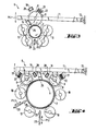
- the processing station 5 is particularly important for the present invention, which is shown on an enlarged scale, particularly in FIGS. 3 and 4, for the case in which the workpieces 2 are to be perforated.
- the device 1 and in particular its work station 5 have a holder for the workpiece 2 to be described in more detail and at least one (FIG. 3) or two (FIG. 4) with perforation needles 8 or the like.
- Carrier body 9 occupied.
- drive means are provided for repeatedly inserting the needles or styli 8 into the surface or wall of the hollow body 2.
- rotatable support rollers or rings 10 are provided as holders for the workpiece 2, and the needle carrier 9 is also a rotating body, the circumference of which is occupied by the needles 8 or the like is and whose axis of rotation runs parallel to the axes of rotation of the support rollers 10 of the hollow body 2 to be perforated and also to the axis thereof. It can be seen in FIGS. 3 and 4 that in the use position the needle carrier 9 with its axis approximates the workpiece so far is that the needles pierce and perforate the wall of the hollow body 2 at least after several revolutions.
- the needle rollers or rings 9 are pivotably mounted relative to the workpiece 2.
- a swivel arm 11 which is fixed in the device 1 via a joint 12 and can be swiveled upwards and then downwards again according to the double arrow Pf 1 from the position shown in FIGS. 3 and 4. It is clear that in the up position of this swivel arm 11, a workpiece 2 can be ejected after its processing or a new workpiece can be inserted for processing.
- the needles 8 can have any profile if the perforation is to have a specific shape.
- the support rollers 10 and also the needle carrier (s) 9 are expediently adjustable to the diameter of the hollow body 2 to be perforated, the needle rollers being adaptable by pivoting the swivel arm 11, while the support rollers can be mounted with their axes displaceable in parallel. It is advantageous that the needle carriers in particular have a drive and the carrier rollers can run along empty. However, it is also possible that at least one of the support rollers 10 has a drive, not shown.
- a gear 13 or the like can be seen on an end face of the needle carrier rollers 9, which belongs to the drive of these needle rollers 9 or forms the drive. With this gear 13 further wheels or a chain or the like can then cooperate.
- the needle carrier 9 can be designed as a needle roller of approximately the length that corresponds to the length of the area of the workpiece 2 to be perforated, in particular that of the entire workpiece 2. It is also indicated in Fig. 2 that z. B. three workpieces can be created and processed at the same time, in particular if 2 knife blades 14 or the like are arranged in at least one space between the support rollers 10 arranged on the circumference for the rotating workpiece. Cutting tools for separating a sleeve with a predetermined length are arranged. 2, for example, three perforated sleeves 15 can be formed from a blank during processing. It can be seen in Fig. 7 that for the separation of individual sleeves 15 from pipes 16 or the like.
- a plurality of knives 14 arranged at a distance from one another are provided and that rings 17 with spaced rings 8 are preferably used for the rotary drive of the workpieces can be provided.
- the focus is on the production of individual sleeves or rings.
- additional perforating devices e.g. H.
- Carrying body 9 filled with needles 8 can be provided, which work holes into the surface of the sleeves 15 simultaneously or subsequently or before the separation.
- the shaft 18, which carries the needle rings 17, belongs to the drive of the processing station 5.
- the needles 8 may not need to pierce the surface of the sleeves 15 if it is only a question of the production of pipe pieces or sleeves 15 and whose perforation is not desired.
- support rollers 10 (not shown in detail) can be provided, these being mainly loose can run along because the needle rings 17 can take over the drive.
- supporting rollers driven with the needle rings 17 in addition to or instead of the shaft 18.
- a plurality of needle rings 17 and / or needle rollers 9 can be provided for the rotary drive and / or for the actual perforation, in particular for larger workpieces 2, these needle rings or rollers in the longitudinal direction one behind the other and / or on the circumference of the workpiece can be distributed.
- the former can be seen in FIG. 7, the latter in FIG. 4.
- the above-described device and in particular the work station 5 shown in FIGS. 3 and 4 allow a perforating process with heated needles 8 without these needles having to be connected to a heater. It is namely possible by the arrangement described above that repeated piercing or intervening at the points of the workpiece 2 to be perforated with one or more needles and that the punctures or interventions are repeated so often and so quickly that the several times in the heat the resulting perforations into the needle tips by the friction itself. Especially when perforating from Thermoplan AG - sticianm plastic existing workpieces 2 the implementation of true perforation is supported from an initially small puncture by said heating or heating and outreach possible.
- the hollow body 2 to be perforated is rotated in this perforation and the rotating body 9 occupied by the needles 8 rotates in the opposite direction, so that a kind of toothing is generated between the needles and the latter perforations are formed.
- the circumferential circle extending through the needle tips dips into the surface of the body to be perforated or even penetrates it, the speed of rotation being able to be selected so that the needle tips repeatedly immersed in the same place produce the abovementioned frictional heat. It is not important that the same needle always hits the same hole, but it is only necessary that some needle always hits the same hole.
- the rotating body 2 to be perforated can be rotated by the rotation of the needle carrier (s) 9 and the positive engagement that occurs in the process.
- the self-heating needles 8 are expediently blown on and / or treated preparatively to adjust their temperature, in particular wetted with a coolant.
- a liquid coolant can be applied, in particular brushed, by atomization or as dripping oil.
- FIGS. 3 and 4 For this purpose, one can see in FIGS. 3 and 4, in addition to the respective needle roller 9 or the like. Perforating tool, axially parallel to this, a channel 19 for blowing air with openings 20 directed against the needles 8. However, through this channel 19 and the openings 20 coolant can also be supplied.
- a brush 21 can be seen in each needle roller 9 for applying a liquid coolant to the needles 8, said brush 21 engaging with its bristles 22 in the area of at least the tips of the needles 8.
- ejector 23 is arranged opposite the attack of the needle rollers 9 or rings 17 and / or cutting knife 14 in the region of the workpiece 2.
- Fig. 3 it is shown that a single ejector is sufficient for a smaller workpiece, while it is indicated in Fig. 4 that several ejectors 23 can be provided, especially for larger workpieces.
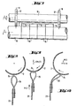
- the design and operation of the ejector 23 can be seen particularly well in FIGS. 8 to 10. It is important that the ejector 23 is connected to the pivot bearing of the needle roller 9 or the like, or at least works synchronously in such a way that when the needle roller swings away 9 of the finished workpiece 2, this is acted upon by the ejector 23 between the support rollers 10 and is lifted out of the latter.
- the ejector 23 is designed as a ruler or the like, which is mounted approximately parallel to the workpiece 2 and has an elastic narrow side 24 which acts on the workpiece 2 and extends over at least part of the workpiece length.
- the ejector 23 in the exemplary embodiment has an elastic lip 25 which has a tube-shaped or loop-shaped cross section for adaptation to workpiece movements taking place during ejection. This makes it possible to gently eject even somewhat flexible workpieces.
- 8 shows the ejector 23 initially in the rest position. When ejecting the ejector 23 is moved in the direction of arrow Pf 2, whereby the workpiece is raised.
- FIGS. 3 and 4 A side view of a schematic representation of the cutting knife (s) 14 can also be seen in FIGS. 3 and 4. It is clear that these cutting knives 14 with their cutting edge 26 are preferably at an acute angle to the surface of the workpiece 2 and preferably gradually during the cutting cut deeper into the workpiece and retractable after cutting while rotating. This retraction movement with simultaneous rotation of the workpiece can bring about an easy release of the knife from the cut formed by it and remove any burr that may occur. To separate short sleeves 15 or the like.
- Ring-shaped workpieces with knife blades 14 that are close to one another, these and in particular their cutting edges can be offset in height, so that they attack the workpiece at different times when it is inserted into the workpiece surface and do not deform it as far as possible and do not deform it generate great cutting resistance.
- Another advantage of the pulling cuts produced by the knife blades 14 described and their cutting edges 26 and the still ongoing rotary movement of the workpieces when the knife blades are pulled out of the cut is that the cutting edges can sharpen the blades again and again, so that the cutting process to a certain extent is self-sharpening.
- the support rollers 10 may have an analog counter-profiling.
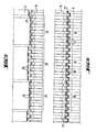
- 5 shows an example in which a strongly profiled support roller 10 engages a workpiece with relatively wide shafts.
- FIG. 6 shows a solution in which the support roller 10 also shown in FIG. 5 for workpieces having ring-shaped profiles 27 has zones 28 and 29 with groups of stronger counter-profiles 30 and those with weaker counter-profiles 31. It can be clearly seen how the stronger profiles 30 fully engage in the profiles 27 of the workpiece, while the weaker counter profiles 31 only partially protrude into the profiles 27, so that the workpiece can adapt well to the support roller in the event of inaccuracies.
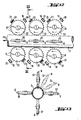
- FIGS. 12 and 13 A modified embodiment of a work station for perforating tubes 2 of any shape in cross section is shown schematically in FIGS. 12 and 13.
- at least one needle wheel in the exemplary embodiment several needle wheels arranged at an angle to one another on the circumference of the hollow body 2 to be perforated, the axes of rotation of which are transverse is arranged to the feed direction of the workpiece 2 indicated by the arrow Pf 4.
- These needle wheels 32 several of which are arranged one behind the other in such a way that their needles 8 can also repeatedly enter the same perforations, cause the workpiece feed if one or more of them are driven.
- the axes of these needle wheels 32 are arranged at right angles to the feed of the workpiece 2 to be perforated and they are also distributed over the circumference of this workpiece 2 so that corresponding rows of per forations can arise.
- a conveyor belt 34 running obliquely in the direction of advance against the needle field 33 is provided, which on the opposite side of the needle field 33 is frictionally and / or positively on the hollow bodies by means of projections, tips or the like 2 attacks and presses them gradually in the direction of advance as they roll onto the needles 8.
- a carrier 35 of this conveyor belt 34 can be adjusted according to the double arrows Pf 7 with regard to its total distance from the needle field 33 and also with regard to its inclined position.
- At least one rotating circular knife 36 and / or at least one is preferably pivotable for the separation of sleeves 15 which can be advanced by means of the conveyor belt 34 acting on their circumference bare knife blade 41 shown in Fig. 11 is provided.
- the needles 8 can preferably be cooled with a gaseous or liquid coolant through bores 37 in their carrier 38.
- the conveyor belt 34 which is designed as a friction belt, can be pressed against the needle field 33 by means of a pressure plate 39, in order to ensure the desired unrolling of the workpieces despite the resistance in the perforating and / or cutting process.
- the conveyor belt In particular for changing the inclined position of the conveyor belt, it can be pivotably mounted on an axis 40 running on one side about an axis 40 parallel to the needle plane. It can be seen that the carrier 35 also carries the knife 36.
Landscapes
- Life Sciences & Earth Sciences (AREA)
- Forests & Forestry (AREA)
- Engineering & Computer Science (AREA)
- Mechanical Engineering (AREA)
- Perforating, Stamping-Out Or Severing By Means Other Than Cutting (AREA)
- Treatment Of Fiber Materials (AREA)
- Drilling And Boring (AREA)
- Sawing (AREA)
- Separation Using Semi-Permeable Membranes (AREA)
Priority Applications (1)
| Application Number | Priority Date | Filing Date | Title |
|---|---|---|---|
| AT83101558T ATE28051T1 (de) | 1982-04-01 | 1983-02-18 | Verfahren und vorrichtung zum perforieren oder zum perforieren und abschneiden rundlauffaehiger hohlkoerper. |
Applications Claiming Priority (2)
| Application Number | Priority Date | Filing Date | Title |
|---|---|---|---|
| DE3212153A DE3212153C2 (de) | 1982-04-01 | 1982-04-01 | Verfahren und Vorrichtung zum Perforieren und/oder Abschneiden runder Hohlkörper |
| DE3212153 | 1982-04-01 |
Publications (3)
| Publication Number | Publication Date |
|---|---|
| EP0090933A2 true EP0090933A2 (fr) | 1983-10-12 |
| EP0090933A3 EP0090933A3 (en) | 1984-11-07 |
| EP0090933B1 EP0090933B1 (fr) | 1987-07-01 |
Family
ID=6159996
Family Applications (1)
| Application Number | Title | Priority Date | Filing Date |
|---|---|---|---|
| EP83101558A Expired EP0090933B1 (fr) | 1982-04-01 | 1983-02-18 | Appareil et méthode pour perforer ou perforer et couper des tubes |
Country Status (8)
| Country | Link |
|---|---|
| US (1) | US5019028A (fr) |
| EP (1) | EP0090933B1 (fr) |
| JP (1) | JPS58186599A (fr) |
| AT (1) | ATE28051T1 (fr) |
| BR (1) | BR8301581A (fr) |
| CA (1) | CA1203157A (fr) |
| DE (2) | DE3212153C2 (fr) |
| ZA (1) | ZA832029B (fr) |
Cited By (2)
| Publication number | Priority date | Publication date | Assignee | Title |
|---|---|---|---|---|
| EP0410616A1 (fr) * | 1989-07-25 | 1991-01-30 | Philip Morris Products Inc. | Appareil à couper et à former des tubes |
| EP0428217A1 (fr) * | 1989-11-16 | 1991-05-22 | Unilever N.V. | Appareil de découpage |
Families Citing this family (14)
| Publication number | Priority date | Publication date | Assignee | Title |
|---|---|---|---|---|
| US5141428A (en) * | 1990-03-16 | 1992-08-25 | Philip Morris Incorporated | Apparatus for cutting thin-walled tubes |
| US5205479A (en) * | 1991-11-15 | 1993-04-27 | The Pillsbury Company | Dough container with preweakened non-peel label |
| US5257560A (en) * | 1992-09-14 | 1993-11-02 | M. C. Molds, Inc. | Trimmer for removing scraping from tops of plastic bottles |
| DE19544330C2 (de) * | 1995-11-28 | 2000-07-27 | Windmoeller & Hoelscher | Nadelwalzenanordnung mit mehreren Nadelwalzen zur Perforierung einer durchlaufenden Materialbahn |
| DE29912657U1 (de) * | 1999-07-27 | 1999-09-23 | Brodbeck Maschinenbau GmbH + Co., 72555 Metzingen | Vorrichtung zum Schneiden von Rohren |
| US20020139228A1 (en) * | 2001-03-27 | 2002-10-03 | Newell Operating Company | Perforated roller cover and methods of manufacture thereof |
| US7204654B2 (en) * | 2003-07-02 | 2007-04-17 | Lexmark International, Inc. | Perforation forming mechanism for use in an imaging apparatus |
| DE102004059394A1 (de) * | 2004-12-09 | 2006-11-16 | Kastriot Merlaku | Vorrichtung zum Herstellen von Luft-Einlassporen oder Lufteinlass-Öffnungen/-Kanäle an einem Trinkhalm-Wand |
| KR100880904B1 (ko) | 2007-08-01 | 2009-02-03 | 정태진 | 다관체 접합 배수부재 천공장치 및 천공방법 |
| DE102011111443A1 (de) * | 2011-08-30 | 2013-02-28 | Sergey Kastalskiy | Trinkhalm mit zusätzlicher Öffnung |
| CN206967605U (zh) * | 2014-12-18 | 2018-02-06 | 惠州市吉瑞科技有限公司深圳分公司 | 一种黄腊管冲裁设备 |
| CN108975051B (zh) * | 2018-08-22 | 2023-11-14 | 深圳市沃尔核材股份有限公司 | 管材收线装置和方法 |
| IT202000013819A1 (it) * | 2020-06-10 | 2021-12-10 | Ima Spa | Macchina e procedimento per la produzione automatizzata di cannucce. |
| IT202000013822A1 (it) * | 2020-06-10 | 2021-12-10 | Ima Spa | Macchina e procedimento per la produzione automatizzata di cannucce. |
Family Cites Families (19)
| Publication number | Priority date | Publication date | Assignee | Title |
|---|---|---|---|---|
| US2272179A (en) * | 1940-08-31 | 1942-02-10 | Yoder Co | Mechanism for cutting bodies into sections |
| US3086288A (en) * | 1955-04-20 | 1963-04-23 | Cavitron Ultrasonics Inc | Ultrasonically vibrated cutting knives |
| US3232298A (en) * | 1963-10-17 | 1966-02-01 | Vernon L Bosley | Cigarette perforating device |
| GB1128691A (en) * | 1965-04-01 | 1968-10-02 | Bristol Aeroplane Plastics Ltd | Methods of and machines for cutting slots in tubes |
| DE1778094C3 (de) * | 1968-03-28 | 1978-12-07 | Fraenkische Isolierrohr- & Metallwaren-Werke, Gebr. Kirchner, 8729 Koenigsberg | Vorrichtung zum fortlaufenden Lochen der Wandung von dünnwandigen Faltenrohren |
| JPS4533038Y1 (fr) * | 1969-05-01 | 1970-12-16 | ||
| US3750503A (en) * | 1970-05-06 | 1973-08-07 | J Mcmillan | Method and means of gang saw lubrication and cooling |
| US3877831A (en) * | 1972-06-13 | 1975-04-15 | Ernest J Maroschak | Method of apparatus for drilling holes in tubes |
| US3848929A (en) * | 1973-06-14 | 1974-11-19 | Engelhard Min & Chem | Water applicator for a pavement grooving machine |
| DE7322161U (de) * | 1973-06-14 | 1977-04-14 | Fa. Heinrich Oltmanns, 2901 Jeddeloh | Vorrichtung zur erzeugung einer lochung in den wellentaelern eines wellrohres, insbesondere fuer draenungen |
| US3847044A (en) * | 1973-11-08 | 1974-11-12 | Hauni Werke Koerber & Co Kg | Method and apparatus for testing wrappers of cigarettes or the like |
| IE41211B1 (en) * | 1975-01-28 | 1979-11-07 | Wavin Pipes Ltd | Production of soil drainage pipes |
| DE2506512C3 (de) * | 1975-02-15 | 1978-09-21 | Adalbert 7850 Loerrach Engel | Textilhulse |
| DE2623851A1 (de) * | 1976-05-28 | 1977-12-08 | Eow Folien Gmbh | Bewegbare vorrichtung zum mehrfachlochen der kunststoff-folie in einem beutelautomaten |
| DE2749894C2 (de) * | 1977-11-08 | 1984-04-12 | Klaus 4803 Steinhagen Kalwar | Verfahren zur Erwärmung von Schnitt-, Loch-, Stanz-, Profilier- oder ähnlichen Werkzeugen und Vorrichtung zur Durchführung des Verfahrens |
| US4319589A (en) * | 1978-04-07 | 1982-03-16 | Molins Limited | Method and apparatus for perforating rod-like articles |
| JPS5837541Y2 (ja) * | 1979-02-06 | 1983-08-24 | 株式会社アマダ | 帯鋸刃案内装置 |
| US4292872A (en) * | 1979-11-21 | 1981-10-06 | Philip Morris Incorporated | Apparatus for perforating hollow cylinders |
| US4414783A (en) * | 1981-08-19 | 1983-11-15 | Buehler Ltd. | Coolant system for rotating blade cutter |
-
1982
- 1982-04-01 DE DE3212153A patent/DE3212153C2/de not_active Expired
-
1983
- 1983-02-18 AT AT83101558T patent/ATE28051T1/de not_active IP Right Cessation
- 1983-02-18 DE DE8383101558T patent/DE3372268D1/de not_active Expired
- 1983-02-18 EP EP83101558A patent/EP0090933B1/fr not_active Expired
- 1983-03-23 ZA ZA832029A patent/ZA832029B/xx unknown
- 1983-03-28 BR BR8301581A patent/BR8301581A/pt not_active IP Right Cessation
- 1983-03-31 CA CA000425128A patent/CA1203157A/fr not_active Expired
- 1983-03-31 JP JP58054102A patent/JPS58186599A/ja active Granted
-
1988
- 1988-07-22 US US07/224,213 patent/US5019028A/en not_active Expired - Lifetime
Cited By (2)
| Publication number | Priority date | Publication date | Assignee | Title |
|---|---|---|---|---|
| EP0410616A1 (fr) * | 1989-07-25 | 1991-01-30 | Philip Morris Products Inc. | Appareil à couper et à former des tubes |
| EP0428217A1 (fr) * | 1989-11-16 | 1991-05-22 | Unilever N.V. | Appareil de découpage |
Also Published As
| Publication number | Publication date |
|---|---|
| JPH03199B2 (fr) | 1991-01-07 |
| ZA832029B (en) | 1983-12-28 |
| EP0090933A3 (en) | 1984-11-07 |
| DE3212153A1 (de) | 1983-10-20 |
| EP0090933B1 (fr) | 1987-07-01 |
| ATE28051T1 (de) | 1987-07-15 |
| DE3212153C2 (de) | 1984-09-13 |
| BR8301581A (pt) | 1983-12-06 |
| DE3372268D1 (en) | 1987-08-06 |
| CA1203157A (fr) | 1986-04-15 |
| US5019028A (en) | 1991-05-28 |
| JPS58186599A (ja) | 1983-10-31 |
Similar Documents
| Publication | Publication Date | Title |
|---|---|---|
| EP0090933B1 (fr) | Appareil et méthode pour perforer ou perforer et couper des tubes | |
| DE2230767C2 (de) | Vorrichtung zum Einschneiden von Öffnungen in Rohre | |
| DE2826362C2 (fr) | ||
| DE3045095C2 (de) | Vorrichtung zum Entfernen von Stanzabfall beim Stanzen von Bögen | |
| DE69010505T4 (de) | Vorrichtung zum entfernen des abfalls von gestanzten zuschnitten. | |
| DE60026383T2 (de) | Vorrichtung zum Schneiden von Materialteilen in günstige Zuschnitte | |
| DE3503094C2 (fr) | ||
| DE1778094B2 (de) | Vorrichtung zum fortlaufenden Lochen der Wandung von dünnwandigen Faltenrohren | |
| DE2810165A1 (de) | Verfahren und vorrichtung zum perforieren von schlaeuchen sowie verfahren zur herstellung einer leitspindel zur verwendung in einer vorrichtung zum perforieren von schlaeuchen | |
| DE3029292A1 (de) | Vorrichtung zum perforieren einer papierbahn | |
| DE2155127A1 (de) | Vorrichtung zum Entgraten von Hohl korpern aus plastischem Werkstoff | |
| DE2643655A1 (de) | Rohrschneidevorrichtung | |
| EP0014358B1 (fr) | Procédé et dispositif pour la fabrication d'une balle en matière cellulaire, pourvue d'une empreinte superficielle | |
| AT17023U1 (fr) | ||
| DE1435299A1 (de) | Verfahren und Vorrichtung zur Herstellung von seitlich geschraeften Polstern,Insbesondere fuer medizinische Zwecke | |
| DE1112881B (de) | Verfahren zur Fertigbearbeitung und Montage eines Perforiermessers zum Bearbeiten von Papier, Pappe, Kunststoff od. dgl. | |
| DE2204855A1 (de) | Verfahren zum perforieren oder lochen von thermoplastischen kunststoffen, insbesondere beschichteten kunststofffolien und einrichtung zur durchfuehrung des verfahrens | |
| CH340700A (de) | Verfahren zum Perforieren von Papier und Einrichtung zur Durchführung dieses Verfahrens | |
| DE655320C (de) | Stanzvorrichtung fuer sproede, bei Druck zerkruemelnde oder zerfallende Materialien,wie Glimmer o. dgl. | |
| DE1753858C3 (de) | Vorrichtung zum fortlaufenden Lochen der Wandung von dünnwandigen Faltenrohren | |
| DE646809C (de) | Vorrichtung zum Herstellen allseitig geschlossener Hohlsteine | |
| DE2330224A1 (de) | Vorrichtung zur erzeugung einer lochung in den wellentaelern eines wellrohres, insbesondere fuer draenungen | |
| AT203352B (de) | Verfahren und Einrichtung zum Perforieren von Papier od. dgl. | |
| AT349858B (de) | Verfahren und vorrichtung zur herstellung von fuer die perforierung von endlosformularen od.dgl. dienenden perforiermessern | |
| DE10158502B4 (de) | Vorrichtung zur Herstellung einer Mikroperforation in Rollladen-Stabstegen |
Legal Events
| Date | Code | Title | Description |
|---|---|---|---|
| PUAI | Public reference made under article 153(3) epc to a published international application that has entered the european phase |
Free format text: ORIGINAL CODE: 0009012 |
|
| AK | Designated contracting states |
Designated state(s): AT BE CH DE FR GB IT LI LU NL |
|
| PUAL | Search report despatched |
Free format text: ORIGINAL CODE: 0009013 |
|
| AK | Designated contracting states |
Designated state(s): AT BE CH DE FR GB IT LI LU NL |
|
| 17P | Request for examination filed |
Effective date: 19840921 |
|
| ITF | It: translation for a ep patent filed | ||
| GRAA | (expected) grant |
Free format text: ORIGINAL CODE: 0009210 |
|
| AK | Designated contracting states |
Kind code of ref document: B1 Designated state(s): AT BE CH DE FR GB IT LI LU NL |
|
| REF | Corresponds to: |
Ref document number: 28051 Country of ref document: AT Date of ref document: 19870715 Kind code of ref document: T |
|
| REF | Corresponds to: |
Ref document number: 3372268 Country of ref document: DE Date of ref document: 19870806 |
|
| ET | Fr: translation filed | ||
| PLBE | No opposition filed within time limit |
Free format text: ORIGINAL CODE: 0009261 |
|
| STAA | Information on the status of an ep patent application or granted ep patent |
Free format text: STATUS: NO OPPOSITION FILED WITHIN TIME LIMIT |
|
| 26N | No opposition filed | ||
| ITTA | It: last paid annual fee | ||
| EPTA | Lu: last paid annual fee | ||
| PGFP | Annual fee paid to national office [announced via postgrant information from national office to epo] |
Ref country code: CH Payment date: 19960214 Year of fee payment: 14 |
|
| PGFP | Annual fee paid to national office [announced via postgrant information from national office to epo] |
Ref country code: NL Payment date: 19960229 Year of fee payment: 14 Ref country code: AT Payment date: 19960229 Year of fee payment: 14 |
|
| PGFP | Annual fee paid to national office [announced via postgrant information from national office to epo] |
Ref country code: LU Payment date: 19960301 Year of fee payment: 14 |
|
| PG25 | Lapsed in a contracting state [announced via postgrant information from national office to epo] |
Ref country code: LU Free format text: LAPSE BECAUSE OF NON-PAYMENT OF DUE FEES Effective date: 19970218 Ref country code: AT Effective date: 19970218 |
|
| PG25 | Lapsed in a contracting state [announced via postgrant information from national office to epo] |
Ref country code: LI Effective date: 19970228 Ref country code: CH Effective date: 19970228 |
|
| PG25 | Lapsed in a contracting state [announced via postgrant information from national office to epo] |
Ref country code: NL Effective date: 19970901 |
|
| REG | Reference to a national code |
Ref country code: CH Ref legal event code: PL |
|
| NLV4 | Nl: lapsed or anulled due to non-payment of the annual fee |
Effective date: 19970901 |
|
| PGFP | Annual fee paid to national office [announced via postgrant information from national office to epo] |
Ref country code: FR Payment date: 20001222 Year of fee payment: 19 |
|
| PGFP | Annual fee paid to national office [announced via postgrant information from national office to epo] |
Ref country code: BE Payment date: 20001229 Year of fee payment: 19 |
|
| PGFP | Annual fee paid to national office [announced via postgrant information from national office to epo] |
Ref country code: GB Payment date: 20010215 Year of fee payment: 19 |
|
| REG | Reference to a national code |
Ref country code: GB Ref legal event code: IF02 |
|
| PGFP | Annual fee paid to national office [announced via postgrant information from national office to epo] |
Ref country code: DE Payment date: 20020115 Year of fee payment: 20 |
|
| PG25 | Lapsed in a contracting state [announced via postgrant information from national office to epo] |
Ref country code: GB Free format text: LAPSE BECAUSE OF NON-PAYMENT OF DUE FEES Effective date: 20020218 |
|
| PG25 | Lapsed in a contracting state [announced via postgrant information from national office to epo] |
Ref country code: BE Free format text: LAPSE BECAUSE OF NON-PAYMENT OF DUE FEES Effective date: 20020228 |
|
| BERE | Be: lapsed |
Owner name: ENGEL ADALBERT Effective date: 20020228 |
|
| GBPC | Gb: european patent ceased through non-payment of renewal fee |
Effective date: 20020218 |
|
| PG25 | Lapsed in a contracting state [announced via postgrant information from national office to epo] |
Ref country code: FR Free format text: LAPSE BECAUSE OF NON-PAYMENT OF DUE FEES Effective date: 20021031 |
|
| REG | Reference to a national code |
Ref country code: FR Ref legal event code: ST |