EP0090938A1 - Système de transducteur et d'élément régulateur électro-mécanique - Google Patents
Système de transducteur et d'élément régulateur électro-mécanique Download PDFInfo
- Publication number
- EP0090938A1 EP0090938A1 EP83101643A EP83101643A EP0090938A1 EP 0090938 A1 EP0090938 A1 EP 0090938A1 EP 83101643 A EP83101643 A EP 83101643A EP 83101643 A EP83101643 A EP 83101643A EP 0090938 A1 EP0090938 A1 EP 0090938A1
- Authority
- EP
- European Patent Office
- Prior art keywords
- pressure
- control member
- transducer
- regulator
- output port
- Prior art date
- Legal status (The legal status is an assumption and is not a legal conclusion. Google has not performed a legal analysis and makes no representation as to the accuracy of the status listed.)
- Withdrawn
Links
- 239000004020 conductor Substances 0.000 claims abstract description 18
- 230000004907 flux Effects 0.000 claims abstract description 12
- 238000004891 communication Methods 0.000 claims abstract description 7
- 230000004044 response Effects 0.000 claims abstract description 6
- 230000001419 dependent effect Effects 0.000 claims 1
- 230000006870 function Effects 0.000 description 5
- 238000010276 construction Methods 0.000 description 3
- 230000003247 decreasing effect Effects 0.000 description 3
- 230000006978 adaptation Effects 0.000 description 2
- 230000001276 controlling effect Effects 0.000 description 2
- 239000000463 material Substances 0.000 description 2
- 238000012986 modification Methods 0.000 description 2
- 230000004048 modification Effects 0.000 description 2
- 229910001158 Alnico 8 Inorganic materials 0.000 description 1
- CWYNVVGOOAEACU-UHFFFAOYSA-N Fe2+ Chemical compound [Fe+2] CWYNVVGOOAEACU-UHFFFAOYSA-N 0.000 description 1
- 238000009825 accumulation Methods 0.000 description 1
- 238000001816 cooling Methods 0.000 description 1
- 230000007423 decrease Effects 0.000 description 1
- 230000003412 degenerative effect Effects 0.000 description 1
- 238000007599 discharging Methods 0.000 description 1
- 239000000428 dust Substances 0.000 description 1
- 230000000694 effects Effects 0.000 description 1
- 239000000446 fuel Substances 0.000 description 1
- 238000010438 heat treatment Methods 0.000 description 1
- 239000000696 magnetic material Substances 0.000 description 1
- 239000002184 metal Substances 0.000 description 1
- 239000000203 mixture Substances 0.000 description 1
- 238000012544 monitoring process Methods 0.000 description 1
- 230000001105 regulatory effect Effects 0.000 description 1
- 238000007789 sealing Methods 0.000 description 1
- 230000000087 stabilizing effect Effects 0.000 description 1
- 239000012815 thermoplastic material Substances 0.000 description 1
Images
Classifications
-
- G—PHYSICS
- G05—CONTROLLING; REGULATING
- G05D—SYSTEMS FOR CONTROLLING OR REGULATING NON-ELECTRIC VARIABLES
- G05D16/00—Control of fluid pressure
- G05D16/20—Control of fluid pressure characterised by the use of electric means
- G05D16/2006—Control of fluid pressure characterised by the use of electric means with direct action of electric energy on controlling means
- G05D16/2013—Control of fluid pressure characterised by the use of electric means with direct action of electric energy on controlling means using throttling means as controlling means
Definitions
- the present invention relates to transducers and to actuator systems employing transducers, e.g. actuator systems having transducers constructed and arranged to produce a vacuum pressure output which varies in value in response to variations in value of an electrical input signal.
- vacuum pressure is used in a general sense to mean a pressure lower than ambient pressure.
- Electric actuators for vehicle components such as EGR valves, passenger compartment heater control valves, or passenger compartment temperature-controlling air stream blend doors and dampers have been inordinately expensive compared to pneumatic actuators capable of performing the same tasks.
- This is particularly true of vacuum pressure operated actuators which, when communicated to a source of vacuum pressure, operate controlled devices quickly and forcefully yet are inexpensive, highly reliable and have long life expectancies.
- positive pressures can be used to actuate vehicle components
- use of vacuum pressure is desirable because pressure hoses, valves, etc. are not subject to accummulations of condensed atmospheric moisture which can freeze and impair performance.
- vacuum pressure sources are usually available in automotive vehicles either because the vehicle intake manifold is typically maintained at vacuum pressure or the vehicle is equipped with a vacuum pump.
- An object of the present invention is to provide a transducer and an actuator system including a transducer for receiving an electrical signal input and producing an actuating output pressure which varies in accordance with variations in the electrical input signal.
- a transducer for producing an output pressure in response to an electrical input signal characterised by a housing defining an input port for communicating with a pressure source, an input port for communicating with ambient atmosphere, and an output port; regulator valving means including a regulator control member movable to control communication between said output port and said input ports to govern the pressure at said output port, said control member being acted upon in use by differential pressure force between said output port and pressure at one of said input ports; and electrical signal responsive actuator means for exerting actuating force on said control member to govern the output pressure as a function of said input signal said actuator means comprising magnetic field producing means supported by said housing adjacent said regulator valving means and a conductor electrically connected across said signal source and disposed in a path of flux produced by said magnetic field producing means, said conductor being supported in force transmitting relationship with said control member and effective to exert force on said control member which varies in relation to changes in signals from said source.
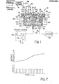
- An actuator system 10 is illustrated in Figure 1 of the drawings and includes a vacuum operated actuator 12, a source 14 of operating vacuum for the actuator 12, an electrical signal source 16 and a transducer 20 for controlling operation of the actuator 12 by the vacuum source 14 in response to changes in electrical signals output from the signal source 16.
- the actuator system 10 is preferably constructed for use in an automotive vehicle in which the actuator moves an actuated device, such as a valve member, to a given position and maintains the member in position until further position adjustment is demanded by changes in the transducer input signal.
- the actuator 12 can be of any suitable or conventional construction, such as a piston subjected to differential pressure between the applied vacuum and ambient or atmospheric pressure and a spring force for opposing motion of the piston by differential pressure and for returning the piston to a "rest" position when there is no differential pressure.
- the illustrated vacuum source 14 is formed by a vacuum producing structure indicated by the reference character 22 and an accumulator 24 evacuated by the vacuum producing structure 22 to provide a "reservoir" of operating vacuum for the system 10.
- the vacuum producing structure 22 can be an engine driven vacuum pump or, in a spark ignition engine, the intake manifold which is normally operated at vacuum pressure.
- a check valve is disposed between the accumulator 24 and the structure 22 so that, in the event the pressure produced by the structure 22 should become greater than that in the accumulator 24 the check valve blocks discharging. of the accumulator.
- the electrical signal source 16 is schematically illustrated and can be of any suitable construction.
- the source 16 includes input circuitry schematically illustrated as provided with an input signal indicative of a sensed condition, such as sensed temperature, and a position feedback signal which is supplied to the signal source input in accordance with the operation of the actuator 12.
- the signal source input signals are algebraically summed and processed by the signal source circuitry to produce a pulse width modulated output signal fed to the transducer 20 on a coaxial line 26.
- the pulse width modulated output signal is formed by a series of constant voltage magnitude, constant frequency pulses.
- the pulses vary in duration and thus the average output signal current from the electrical signal source 16 to the transducer 20 is varied.
- the output pulse widths increase, the current to the transducer increases causing the vacuum output to the actuator to increase ( SEE FIGURE 2).
- the output pulse width decreases the transducer output vacuum level is reduced accordingly.
- the transducer 20 thus supplies the actuator with regulated operating vacuum pressure varying as a function of the variations in the electrical signal input to it from the signal source 16.
- the preferred transducer 20 comprises a housing assembly 30, a vacuum regulator 40 disposed within the housing assembly 30 and an electric signal responsive actuator 42 for controlling the regulator 40.
- the housing assembly 30 defines input ports 32,34 communicating to the vacuum source 14 and atmospheric air, respectively, and an output port 36 communicating with the actuator 12.
- the housing assembly also defines an electrical connector structure 38 to which the coaxial line 26 carrying the pulse width modulated signals from the signal source is connected to the housing assembly.
- the housing assembly 30 includes a cup-like body 50 defining an interior chamber 52 including an output vacuum chamber portion 52a at the closed end of the body 50.
- the input port 32 and the output port 36 are both formed in the closed end of the body 50 with these ports being formed within projecting vacuum hose connectors formed integrally with the body 50.
- the open end of the body 50 has an annular mounting flange 54 extending about its periphery.
- the mounting flange 54 confronts the outer periphery of a annular assembly plate 56 disposed across the open end of body 50 and having an inner pheripheral portion 57 supporting the regulator 40.
- a projecting annular land 58 extends into the housing member 50 and bears against the signal responsive actuator.42 to maintain the actuator 42 assembled in its operative position.
- a cover member 60 overlies the assembly plate 56.
- the cover member 60 defines the atmospheric air input port 34, part of the connector structure 38 and an atmospheric pressure chamber 61 adjacent the regulator 40.
- the cover member 60 and the plate 56 are firmly clamped to the mounting flange 54 by an annular clamping ring 62 disposed around the outer periphery of the housing.
- the transducer 20 can be mounted in any suitable location and orientation since it is connected to its associated components by flexible vacuum hoses and an electric line.
- a mounting bracket 64 is attached to the housing assembly 30 for this purpose.
- the body 50, assembly plate 56 and cover member 60 are preferably formed from molded thermoplastic material and are illustrated as such. These parts can as well be formed from any-suitable non-magnetic die-cast metal.
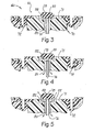
- the preferred regulator-40 includes a control member 70 .extending from the actuator 42 and which is movable to control communication between the output port and the input ports to govern the pressure level supplied to the actuator 12.
- the control member 70 is tubular and generally cylindrical forming a movable valve body portion 71 at its end adjacent the assembly plate 56.
- the regulator 40 further comprises a flexible rubber-like diaphragm 72 engaging the valve body portion 71, a-fixed valve body 76, and a valving member 78 coacting with the movable valve body portion 71 and the fixed valve body 76.
- the valve body portion 71 defines a central valve body passage 80 extending axially through it and communicating with the output chamber portion 52a.
- a valve seat 82 extends about the end of the passage 80 for engagement with the valving member 78.
- the fixed valve body 76 is preferably a thin walled rigid tube disposed within the passage 80 and communicating vacuum from the input vacuum port 32 to the regulator 40.
- the fixed valve body tube is rigidly supported in the housing assembly 30 and sealed in place to prevent leakage between the input port and the housing assembly interior.
- the fixed valve body defines an annular valve seat 88 at its projecting end which is sealingly engageable with the valving member 78.
- the diameter of the valve body tube is smaller than the control member passage 80 to permit free flow between them.
- the valving member 78 is preferably a button-like structure molded integrally with the rubber-like diaphragm 72 and urged resiliently toward sealing engagement with the seat 82 by narrow tongue-like strips of the diaphragm material (see FIGURE 1) continuous with the valving member and the diaphragm.
- the diameter of the member 78 is greater than that of the seat 82 so the member 78 can sealigly engage the seat 82 as well as the fixed valve body seat 88.
- the output pressure chamber portion 52a is alternatively communicable with the vacuum source pressure and the atmospheric pressure chamber 61 to alter the output vacuum from the transducer 70 to the actuator 12.
- the valve body portion 71 moves in a direction away from the output chamber 52a, as shown by FIGURE 4, the valving member 78 is carried by the valve body 71 so that it is and remains sealingly engaged on the seat 82 while being disengaged from the annular seat 88 formed by the end of the fixed valve body tube 76.
- the position of the movable valve body portion 71 is determined by forces acting on it applied by the regulator actuator 42 and by an output pressure responsive feedback force created by differential pressure acting on the effective areas of the valve body portion 71 and the diaphragm 72 between the chamber 61 and the output chamber 52a.
- the tube forming the valve 76 has an extremely small cross sectional area so that the differential pressure force attributable to the source vacuum and atmospheric pressure acting across the effective area of the tube- is relatively small.
- the feedback force is created by dif- ' ferential pressure acting on the effective area provided by the diaphragm 72 and the valve body portion 71.
- the diaphragm 72 is sealed about its outer perimeter to the assembly plate 56 and is sealed to the valve body portion 71 about its inner perimeter.
- the diaphragm and valve body form a movable wall between the output and atmospheric air chamber pressures so that a feedback pressure force which varies according to transducer output pressure is exerted on the valve body 71.
- the regulator actuator and feedback forces act in opposition to each other and always tend to balance with the valve body portion 71 positioned so that the valving member 78 blocks communication between the output chamber 52a and both the vacuum source and the atmospheric chamber 61 (i.e. the position illustrated by FIGURE 3).
- the regulator actuator force applied to the valve body portion 71 increases (moving the valve body 71 from the position illustrated by FIGURE 3 to the position illustrated by FIGURE 4) the regulator output vacuum increases thus increasing the differential pressure feedback force so that the valve body portion 71 returns to the position illustrated by FIGURE 3 with a stable, larger output vacuum pressure established in the output chamber 52a. If the regulator actuator force is decreased (tending to shift the valve body 71 to its position illustrated by FIGURE 5) the regulator output vacuum is decreased, decreasing the differential pressure feedback force acting on the valve body 71 and resulting in the valve body 71 being again positioned as illustrated by FIGURE 3.
- the differential pressure feedback force acting on the valve body 7 1 and the diaphragm 72 thus provides degenerative feedback. in the form of a stabilizing force which changes in magnitude to oppose any unbalanced regulator actuator force on the valve body 71.
- the valve body 71 thus always tends to remain essentially stationary and in the position illustrated by FIGURE 3.
- the electrical signal responsive regulator actuator 42 produces variable electro-magnetic forces applied to the regulator control member 70 to govern the vacuum pressure output from the transducer 20.
- the actuator 42 comprises a magnetic field producing assembly 100 supported adjacent the regulator 40 which coacts with an electric signal responsive conductor 101 disposed in the magnetic field to produce electro-magnetic force applied to the regulator control member 70 which varies according to the transducer input signal.
- the magnetic field producing assembly 100 comprises a permanent magnet 102 and pole. pieces 104, 106 for containing and directing the magnetic flux produced by the magnet.
- the assembly 100 is preferably.supported adjacent the regulator within the housing 30.
- the permanent magnet 102 is formed by a torus of magnetic material, such as Alnico 8, and defines a generally rectangular cross-sectional shape with smooth planar axial faces.
- the pole piece 104 defines a central cylindrical body 110 having a radially extending flange 112 supported adjacent the closed end of the housing body 50. The outer periphery of the flange 112 fits snugly against the housing wall and the magnet 102 is seated in intimate face contact with the adjacent surface of the flange 112.
- the central portion of the pole piece body 110 defines a flow passage 113 through which the vacuum souce is communicated to the regulator 40 by the tubular fixed valve 76.
- the valve tube 106 is sealed in place in the passage 113 and the' passage is aligned with the input port 32.
- the pole piece 104 is seated on an O-ring seal surrounding the input port 32 and the adjacent end of the passage 113 so that the vacuum source is sealed off from the remainder of the housing assembly interior.
- the pole piece 106 is formed by a flat annulus supported atop the magnet 102 in intimate surface contact with the adjacent axial face of the magnet.
- the inner periphery of the pole piece 106 is cylindrical and extends about the outer periphery of the pole piece body 110 to define a narrow annular gap 116 through which magnetic flux is directed between the adjacent pole pieces.
- the pole pieces are formed from suitabe ferrous materials and are each of a size and shape adequate to conduct all of the magnetic flux from the magnet 102 so that the magnetic field is maintained substantially wholly within the transducer 20.
- the pole pieces direct and channel the magnetic flux through the gap 116 where the flux is concentrated.
- the regulator control member 70 includes a tubular body portion 120 projecting from the regulator valve body portion 71 toward the pole piece 74, a radial flange 122 at the end of the body portion 120 and a skirt-like electrical conductor supporting bobbin 124 extending axially from the flange 122 and disposed in the air gap 116.
- the electric signal conductor 101 is preferably formed by a fine insulated wire coil which is helically wound on and bonded in place to the bobbin 124. The ends of the coil 101 are connected across the electrical signal source 16 by a plug type connector 130 which is fixed to and sealed in place in the assembly plate 56 and projects through the cover 60 into a female receptacle molded into the cover member.
- FIGURE 2 graphically depicts average signal source output current increasing over a given time interval with the transducer output vacuum increasing accordingly.
- the passage 80 through the tubular control member body portion forms an air passage about the vacuum source input tube 76 for communicating with the output chamber portion 52a via a passage 132 through the pole piece body 110. Accordingly when the signal current level is reduced, the regulator control member 70 moves to its position illustrated by Figure 5 to momentarily communicate the output chamber to atmospheric pressure in the chamber 61. Air flows to the output chamber through the passage 80 and the pole piece body passage 132. The air flow path avoids the necessity of atmospheric air flowing through the air gap 116 which might otherwise result in accumulation of dust or dirt in the gap and impede operation of the regulator.
- an actuator system constructed according to a preferred embodiment of the present invention includes an electrical signal source, a pressure source, a pressure operated actuator device, and a transducer for communicating controlled operating pressure to the output device which varies as a function of an electrical input signal.
- a preferred transducer comprises a housing defining an input port communicating with a pressure source, an input port communicating with ambient atmosphere and an output port.
- a regulator valving assembly including a control member movable to control communication between the output port and the input ports is contained by the housing.
- An electric signal responsive actuator acts on the regulator control member so that the pressure at the output port varies as a function of signal variations from the signal source.
- the signal responsive actuator comprises a magnetic field producing structure supported by the housing adjacent the regulator and a conductor electrically connected across the signal source and disposed in a flux path produced by the field producing assembly. The conductor is supported in force transmitting relationship with the regulator control member to move it and alter the output pressure.
Landscapes
- Physics & Mathematics (AREA)
- Fluid Mechanics (AREA)
- General Physics & Mathematics (AREA)
- Engineering & Computer Science (AREA)
- Automation & Control Theory (AREA)
- Control Of Fluid Pressure (AREA)
Applications Claiming Priority (4)
| Application Number | Priority Date | Filing Date | Title |
|---|---|---|---|
| JP4325582U JPS58146171U (ja) | 1982-03-29 | 1982-03-29 | 電流制御負圧伝達装置 |
| JP43255/82 | 1982-03-29 | ||
| US36579382A | 1982-04-05 | 1982-04-05 | |
| US365793 | 1982-04-05 |
Publications (1)
| Publication Number | Publication Date |
|---|---|
| EP0090938A1 true EP0090938A1 (fr) | 1983-10-12 |
Family
ID=26383004
Family Applications (1)
| Application Number | Title | Priority Date | Filing Date |
|---|---|---|---|
| EP83101643A Withdrawn EP0090938A1 (fr) | 1982-03-29 | 1983-02-21 | Système de transducteur et d'élément régulateur électro-mécanique |
Country Status (2)
| Country | Link |
|---|---|
| EP (1) | EP0090938A1 (fr) |
| CA (1) | CA1191127A (fr) |
Cited By (1)
| Publication number | Priority date | Publication date | Assignee | Title |
|---|---|---|---|---|
| EP0393248A3 (fr) * | 1989-04-17 | 1991-02-06 | Coltec Industries Inc | Régulateur de pression |
Citations (2)
| Publication number | Priority date | Publication date | Assignee | Title |
|---|---|---|---|---|
| US4079753A (en) * | 1976-09-27 | 1978-03-21 | Midland-Ross Corporation | Electrically responsive static-pressure regulating valve |
| GB1551039A (en) * | 1976-08-06 | 1979-08-22 | Ici Ltd | Conversion of electric to pneumatic signals |
-
1983
- 1983-02-21 EP EP83101643A patent/EP0090938A1/fr not_active Withdrawn
- 1983-03-24 CA CA000424396A patent/CA1191127A/fr not_active Expired
Patent Citations (2)
| Publication number | Priority date | Publication date | Assignee | Title |
|---|---|---|---|---|
| GB1551039A (en) * | 1976-08-06 | 1979-08-22 | Ici Ltd | Conversion of electric to pneumatic signals |
| US4079753A (en) * | 1976-09-27 | 1978-03-21 | Midland-Ross Corporation | Electrically responsive static-pressure regulating valve |
Cited By (1)
| Publication number | Priority date | Publication date | Assignee | Title |
|---|---|---|---|---|
| EP0393248A3 (fr) * | 1989-04-17 | 1991-02-06 | Coltec Industries Inc | Régulateur de pression |
Also Published As
| Publication number | Publication date |
|---|---|
| CA1191127A (fr) | 1985-07-30 |
Similar Documents
| Publication | Publication Date | Title |
|---|---|---|
| CA1220114A (fr) | Transducteur manostatique pour soupape | |
| US6029703A (en) | Pressure solenoid control valve with flux shunt | |
| US4858886A (en) | Electromagnetic valve | |
| US4368366A (en) | Pneumatically operated device with valve and switch mechanisms | |
| US4356802A (en) | Valve system for regulating the idling speed of Otto engines, particularly automobile engines | |
| US4522371A (en) | Proportional solenoid valve | |
| US4469079A (en) | Exhaust gas recirculation (EGR) system | |
| US5509395A (en) | Canister purge flow regulator | |
| US4875499A (en) | Proportional solenoid valve | |
| EP0229315B1 (fr) | Dispositif de commande de la vitesse de ralenti pour moteur de véhicule | |
| US4534375A (en) | Proportional solenoid valve | |
| US3659499A (en) | Vacuum motor adapted for use in a vehicle speed control mechanism | |
| US4715396A (en) | Proportional solenoid valve | |
| US6068237A (en) | Proportional variable bleed solenoid valve with single adjustment pressure calibration | |
| US4266517A (en) | Differential pressure switch device responsive to differential pressure and temperature change | |
| US4411406A (en) | Electromagnetic flow control valve assembly | |
| US4469127A (en) | Signal generating device in response to the degree of opening of a throttle valve | |
| US4953825A (en) | Electro-magnetic proportional flow control valve | |
| US4176633A (en) | Governor apparatus and system | |
| US4274376A (en) | Governor apparatus and system | |
| US3572214A (en) | Vacuum motor adapted for use in a vehicle speed control mechanism | |
| EP0090938A1 (fr) | Système de transducteur et d'élément régulateur électro-mécanique | |
| CA2219030C (fr) | Robinet pressostatique a commande electrique | |
| US4756234A (en) | Vacuum and electric cruise control actuator | |
| EP0077599A1 (fr) | Electrovanne proportionnelle |
Legal Events
| Date | Code | Title | Description |
|---|---|---|---|
| PUAI | Public reference made under article 153(3) epc to a published international application that has entered the european phase |
Free format text: ORIGINAL CODE: 0009012 |
|
| AK | Designated contracting states |
Designated state(s): DE FR IT SE |
|
| 17P | Request for examination filed |
Effective date: 19840213 |
|
| STAA | Information on the status of an ep patent application or granted ep patent |
Free format text: STATUS: THE APPLICATION HAS BEEN WITHDRAWN |
|
| 18W | Application withdrawn |
Withdrawal date: 19851025 |
|
| RIN1 | Information on inventor provided before grant (corrected) |
Inventor name: HALL, DALE G. |