EP0090942A2 - Schweisspistole - Google Patents
Schweisspistole Download PDFInfo
- Publication number
- EP0090942A2 EP0090942A2 EP83101815A EP83101815A EP0090942A2 EP 0090942 A2 EP0090942 A2 EP 0090942A2 EP 83101815 A EP83101815 A EP 83101815A EP 83101815 A EP83101815 A EP 83101815A EP 0090942 A2 EP0090942 A2 EP 0090942A2
- Authority
- EP
- European Patent Office
- Prior art keywords
- welding
- housing
- welding torch
- shaft
- torch
- Prior art date
- Legal status (The legal status is an assumption and is not a legal conclusion. Google has not performed a legal analysis and makes no representation as to the accuracy of the status listed.)
- Granted
Links
Images




Classifications
-
- B—PERFORMING OPERATIONS; TRANSPORTING
- B23—MACHINE TOOLS; METAL-WORKING NOT OTHERWISE PROVIDED FOR
- B23K—SOLDERING OR UNSOLDERING; WELDING; CLADDING OR PLATING BY SOLDERING OR WELDING; CUTTING BY APPLYING HEAT LOCALLY, e.g. FLAME CUTTING; WORKING BY LASER BEAM
- B23K9/00—Arc welding or cutting
- B23K9/12—Automatic feeding or moving of electrodes or work for spot or seam welding or cutting
-
- B—PERFORMING OPERATIONS; TRANSPORTING
- B23—MACHINE TOOLS; METAL-WORKING NOT OTHERWISE PROVIDED FOR
- B23K—SOLDERING OR UNSOLDERING; WELDING; CLADDING OR PLATING BY SOLDERING OR WELDING; CUTTING BY APPLYING HEAT LOCALLY, e.g. FLAME CUTTING; WORKING BY LASER BEAM
- B23K9/00—Arc welding or cutting
- B23K9/24—Features related to electrodes
- B23K9/28—Supporting devices for electrodes
- B23K9/287—Supporting devices for electrode holders
Definitions
- the present invention relates to a welding torch for use in arc welding robots.
- Robots have been introduced at a rapid rate in recent years for practical use in arc welding applications. As more and more robot arc welders are used, various unexpected demands have arisen at locations where such welders are used. The present invention has been devised in an effort to meet one of such demands.
- the welding process employing articulate arc welding robots that can be "taught,” which are most widely used at present, is generally as follows: First, a commercially available integral standard welding torch having a current conducting cable, a welding rod feeder conduit, a gas tube and other components is attached to the end of the arm of the arc welding robot. Then, the robot is "taught” by leading the end of the welding torch through motions along a weld line along which welding is to be performed. During this teaching process, positions along the torch movement path are recorded by a computer associated with the robot to thereby enable the latter to learn welding locations.
- the required current, welding rod, and gas are supplied to the torch to effect arc welding successively at the locations recorded in the computer.
- the robot training process usually takes the operator a few hours. During such a long teaching period, there is a greater tendency for the operator to allow the tip end of the welding torch to collide with the work inadvertently or through error. When the welding torch hits the work, the torch becomes deformed or damaged, and the operator has to repeat the teaching process performed before the accident occurred.
- a welding torch comprising a housing adapted to be supported on a distal end of a robot arm, a torch nozzle movably supported on a distal end of the housing, a shaft movably mounted in the housing and movable in response to the movement of the torch nozzle, and switch means-mounted in the housing and actuatable in response to a movement of the shaft for generating a signal to stop the movement of the robot arm.
- Figs. 1 through 6 illustrate a welding torch constructed in accordance with one embodiment of the present invention.
- An articulated arc welding robot has an arm end 1 including a connector arm 3.
- a welding torch 2 with a mechanism for preventing the torch from being deformed on collision is supported on the connector arm 3.
- the welding torch 2 comprises a torch nozzle 2a, a conduit 2b for feeding a welding rod or wire electrode, a gas tube 2c for supplying inert gas to the area of the weld, a signal cable 2d for delivering a signal from a limit switch (described later), and a current conducting cable 2e.
- a hollow cylindrical center shaft 2f has one end coupled to the nozzle 2a and the other end shaped as a conical portion.
- the center shaft 2f has an axial central through hole for the passage of the welding rod fed through the conduit 2b and the inert gas supplied by the gas tube 2c, and also includes a central flange projecting radially outwardly.
- a hollow cylindrical switch shaft 2g has at one end a hollow cylindrical recess in which the conical end of the center shaft 2f can move radially,a conically shaped portion and a hollow cylindrical slot contiguous thereto at a central portion, and at the other end a stepped cylindrical portion for actuating the limit switch and a cylindrical portion contiguous thereto.
- the switch shaft 2g also has an axial central through hole for the passage of the welding rod and the inert gas supplied through the conduit 2b and the gas tube 2c, respectively.
- a ball shaft 2h has at one end partly spherical portions held against the conical portions of the center shaft 2f and the switch shaft 2g, and at the other end a cylindrical portion 22h received with a force fit in the hollow cylindrical recess contiguous to the conical portion of the switch shaft 2g.
- the ball shaft 2h also has an axial central through hole for the passage of the welding rod and the inert gas fed through the conduit 2b and the gas tube 2c, respectively.
- the limit switch which is denoted by 2i, can be actuated by an axial movement of the switch shaft 2g to generate a stop signal delivered over the signal cable 2d to a control means (not shown), for stopping the movement of the arm end 1 of the robot arc welder.
- a housing 2k has a partly spherical portion on its outer peripheral surface.
- the housing 2k also has in one end a through hole and in the other end a recess in which the limit switch 2i and the rotation prevention cover 2j are fixedly mounted.
- the center shaft 2f, the switch shaft 2g and the ball shaft 2h are accommodated in the housing 2k for axial movement in unison.
- a retainer 21 is assembled in position between the switch shaft 2g and the housing 2k and has a central through hole in which the switch shaft 2g is axially slidable received.
- the retainer 2l also has in one end a recess allowing an acutator arm of the limit switch 2i to be normally kept out of interference with the switch shaft 2g, and in the other end a cavity in which the retainer 2l engages the rotation prevention cover 2j.
- a compression coil spring 2m acts between the switch shaft 2g and the retainer 2l to force the switch shaft 2g in the axial direction to support the center shaft 2f fixed to the torch nozzle 2a through spherical contact with the ball shaft 2h.
- a composite bearing .2n includes a central stroke bearing 2p (described later) which is axially movable and rotatable about its own axis, and a spherical plain bearing disposed at a periphery thereof for allowing radial tiltable movement.
- the stroke bearing 2p extends in surrounding relation to the central shaft 2f with its outer peripheral surface located in a space in the housing 2k and its inner peripheral surface disposed around the cylindrical portion of the switch shaft 2g.
- the spherical plain bearing of the composite bearing 2n is mounted in the housing 2k through the intermediary of a spacer 2 0 .
- the composite bearing 2n and the spacer 2o are fixed by a bracket 2q to a hollow cylindrical portion of the housing 2k.
- the current conducting cable 2e is electrically coupled to a conductive spacer 2r electrically connected to the torch nozzle 2a through a plurality of bendable lead wires 2s such as braided copper wires (Fig. 3).
- the limit switch 2i is electrically coupled to a connector 2t and attached to the housing 2k by a plate 2u (Fig. 2).
- the limit switch 2i is covered by a cover 2w.
- the teaching operation of the welding torch proceeds as follows in the case of an accidental collision:
- the torch nozzle 2a collides with the work W in the direction of the arrows M or N, as shown in F ig. 5 or 6, through carelessness of the operator while welding positions are being taught to the robot, reactive forces due to the collision are imparted from the torch nozzle 2a successively through the center shaft 2f and the ball shaft 2h to the switch shaft 2g, which is caused to slide axially in the housing 2k.
- the switch shaft 2g then moves the actuator arm of the limit switch 2i to bring its contacts into mutual contact.
- the limit switch 2i issues a signal to stop the movement of the robot, thus making the operator awareof the torch collision brought about through the erroneous action. Knowing that this collision has occurred, the operator can now retract the welding torch 2 to the position assumed prior to the collision, and continue the teaching process from that position.
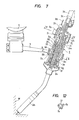
- Figs. 7 through 12 show a welding torch according to another embodiment of the present invention.
- the welding torch includes a curved nozzle which has a greater tendency to erroneously collide at its distal end with the work during the robot teaching process.
- the welding torch has a mechanism for preventing the curved nozzle from being deformed upon collision and is supported by the connector arm 3 on the arm end 1 of the articulate arc welding robot.
- the welding torch 2 includes a center shaft 2f having one end secured to the curved nozzle, indicated at 2a, and the other end shaped in a conical configuration.
- the center shaft 2f has an axial through hole serving as a passage for the welding rod or wire electorde and the inert gas supplied as aforementioned.
- the center shaft 2f also has a plurality of V-shaped grooves 2x (Fig. 12) defined in its central outer periphery.
- the welding torch 2 includes a switch shaft 2g, a limit switch 2i for controlling axial movement of the switch shaft 2g, and a rotation prevention cover 2j.
- a composite bearing 2n has a central stroke bearing 2p axially movable and rotatable about its own axis, and a spherical plain bearing disposed at a peripheral portion for allowing radial tiltable movement.
- the stroke bearing 2p is disposed in surrounding relationship to the center shaft 2f.
- the stroke bearing 2p has an outer peripheral surface positioned in a space in the housing 2k and an inner peripheral surface mounted on a cylindrical portion of the switch shaft 2g.
- the limit switch 2i is attached to the housing 2k by a plate 2u.
- the switch shaft 2g is controlled in its rotational movement by a limit switch 2A.
- Leaf spring pins 2B have leaf springs 2y secured as by riveting to an axial end of the switch shaft 2g and supporting semispherical bodies resiliently forced respectively into the V-shaped grooves 2x in the center shaft 2f (Fig. 12).
- the spherical plain bearing is mounted in the housing 2k through a spacer 2o interposed therebetween.
- the mechanism for positioning the switch shaft 2g in its rotational direction comprises a ball shaft 2I (Figs. 8 and 11) having a semispherical distal end, a stroke bearing 2D for supporting the ball shaft 2I in its axial movements, a compression coil spring 2E, a cap 2F, a retaining ring 2G, and a casing 2H.
- a ball shaft 2I (Figs. 8 and 11) having a semispherical distal end, a stroke bearing 2D for supporting the ball shaft 2I in its axial movements, a compression coil spring 2E, a cap 2F, a retaining ring 2G, and a casing 2H.
- Other parts in Figs. 7 through 12 are denoted by like or corresponding reference characters in Figs. 1 through 6, and will not be described in detail.
- the curved torch nozzle 2a When the curved torch nozzle 2a happens to hit the work, as shown in Figs. 9, 10 or 11 through inadvertence of the operator while the robot is being taught welding positions, the curved torch nozzle 2a pushes or rotates the switch shaft 2g through the center shaft 2f and the ball shaft 2h until actuator arms of the limit switches 2i or 2A located closely to the switch shaft 2g are depressed.
- the limit switches 2i or 2A issue signals to stop the movement of the robot. The operator is thus informed that the welding torch has inadvertently been brought into a collision with the work, and can withdraw the welding torch back to a proper position assumed prior to the collision.
- the welding torch is prevented from being deformed or otherwise damaged, and can be moved along from the colliding position to continuously teach the robot. Since it is not necessary to repeat the entire teaching process as has conventionally been required due to the deformation or damage of the welding torch resulting from the collision, the teaching time is greatly reduced and the operator is relieved of undue mental fatigue.
Landscapes
- Engineering & Computer Science (AREA)
- Physics & Mathematics (AREA)
- Plasma & Fusion (AREA)
- Mechanical Engineering (AREA)
- Manipulator (AREA)
- Arc Welding In General (AREA)
Applications Claiming Priority (4)
| Application Number | Priority Date | Filing Date | Title |
|---|---|---|---|
| JP3040882A JPS58148076A (ja) | 1982-02-26 | 1982-02-26 | 衝突変形防止機構付溶接ト−チ |
| JP30408/82 | 1982-02-26 | ||
| JP122616/82 | 1982-07-14 | ||
| JP12261682A JPS5913574A (ja) | 1982-07-14 | 1982-07-14 | 衝突変形防止機構付溶接ト−チ |
Publications (3)
| Publication Number | Publication Date |
|---|---|
| EP0090942A2 true EP0090942A2 (de) | 1983-10-12 |
| EP0090942A3 EP0090942A3 (en) | 1984-09-05 |
| EP0090942B1 EP0090942B1 (de) | 1987-07-15 |
Family
ID=26368744
Family Applications (1)
| Application Number | Title | Priority Date | Filing Date |
|---|---|---|---|
| EP83101815A Expired EP0090942B1 (de) | 1982-02-26 | 1983-02-24 | Schweisspistole |
Country Status (4)
| Country | Link |
|---|---|
| US (1) | US4540869A (de) |
| EP (1) | EP0090942B1 (de) |
| KR (1) | KR890002025B1 (de) |
| DE (1) | DE3372451D1 (de) |
Cited By (3)
| Publication number | Priority date | Publication date | Assignee | Title |
|---|---|---|---|---|
| US4600824A (en) * | 1984-09-10 | 1986-07-15 | Moerke Delford A | Arc welding system and docking assembly therefor |
| EP0307544A3 (de) * | 1987-07-17 | 1989-09-13 | Raycon Textron Inc. | Bruchfestes Endstück zur Abstrahlung eines Laserstrahls |
| US10150217B2 (en) * | 2014-12-10 | 2018-12-11 | Fanuc Corporation | Tool adapter for robot wrist and robot with tool adapter attached thereto |
Families Citing this family (28)
| Publication number | Priority date | Publication date | Assignee | Title |
|---|---|---|---|---|
| JPS60127992A (ja) * | 1983-12-15 | 1985-07-08 | 三菱電機株式会社 | 産業用ロボツトのハンド装置 |
| US4725190A (en) * | 1984-11-27 | 1988-02-16 | Mitsubishi Denki Kabushiki Kaisha | Hand system of industrial robot |
| DE3545505C2 (de) * | 1985-12-20 | 1995-08-10 | Kuka Schweissanlagen & Roboter | Verfahren und Vorrichtung zum Aufsuchen und Verfolgen einer Kehlnaht beim Schutzgas-Lichtbogenschweißen |
| US4797564A (en) * | 1986-08-25 | 1989-01-10 | Erickson Tool Company | Robot overload detection mechanism |
| US4711985A (en) * | 1986-12-24 | 1987-12-08 | Cincinnati Milacron Inc. | Interference detector for laser cutting machine |
| US4744308A (en) * | 1987-02-24 | 1988-05-17 | National Castings, Inc. | Combined center plate/center filler for railway freight cars |
| DE3825345A1 (de) * | 1988-07-26 | 1990-02-01 | Kuka Schweissanlagen & Roboter | Schweissbrenner |
| GB2229296B (en) * | 1989-03-03 | 1993-08-11 | Mitsubishi Heavy Ind Ltd | Teaching playback type robot |
| US5040915A (en) * | 1989-03-31 | 1991-08-20 | Tweco Products, Inc. | Breakaway mount |
| US5386092A (en) * | 1991-11-04 | 1995-01-31 | Unitek Equipment Inc. | Fast response weld head |
| US5225647A (en) * | 1991-11-04 | 1993-07-06 | Unitek Equipment Inc. | Motorized weld head |
| US5562843A (en) * | 1991-12-28 | 1996-10-08 | Joven Electric Co., Ltd. | Industrial robot with contact sensor |
| US5451117A (en) * | 1994-01-24 | 1995-09-19 | W. Tregaskiss, Ltd. | Keyed alignment system |
| US6166506A (en) * | 1998-06-19 | 2000-12-26 | Tregaskiss, Ltd. | Wireless safety clutch |
| US6130407A (en) * | 1998-07-29 | 2000-10-10 | Tregaskiss, Ltd. | Arc welding torch |
| US6218639B1 (en) * | 1999-11-10 | 2001-04-17 | Jason Bulle | Plasma torch cutting system |
| US6346751B1 (en) | 2000-02-14 | 2002-02-12 | Ocim, S.R.L. | Safety tool mount for robotic apparatus |
| AT411882B (de) * | 2002-10-08 | 2004-07-26 | Fronius Int Gmbh | Abschaltbox für eine roboteranlage |
| DE102005054860B4 (de) * | 2005-11-15 | 2008-04-24 | Eads Deutschland Gmbh | Schweißdüse |
| US10864640B1 (en) | 2017-12-26 | 2020-12-15 | AGI Engineering, Inc. | Articulating arm programmable tank cleaning nozzle |
| US11413666B1 (en) | 2018-02-13 | 2022-08-16 | AGI Engineering, Inc. | Vertical travel robotic tank cleaning system |
| US11031149B1 (en) | 2018-02-13 | 2021-06-08 | AGI Engineering, Inc. | Nuclear abrasive slurry waste pump with backstop and macerator |
| US10786905B1 (en) | 2018-04-16 | 2020-09-29 | AGI Engineering, Inc. | Tank excavator |
| US11577287B1 (en) | 2018-04-16 | 2023-02-14 | AGI Engineering, Inc. | Large riser extended reach sluicer and tool changer |
| HUE068879T2 (hu) | 2018-06-11 | 2025-01-28 | Alex G Innes | Programozható tisztítórendszer vasúti kocsi tartályához |
| US11267024B2 (en) | 2018-06-11 | 2022-03-08 | AGI Engineering, Inc. | Programmable tank cleaning nozzle |
| CA3124669A1 (en) * | 2018-12-23 | 2020-07-02 | AGI Engineering, Inc. | Programmable tank cleaning nozzle |
| CN116079195B (zh) * | 2023-04-07 | 2023-07-07 | 广东隆崎机器人有限公司 | 一种末端执行器及弧焊机器人 |
Family Cites Families (10)
| Publication number | Priority date | Publication date | Assignee | Title |
|---|---|---|---|---|
| US3171012A (en) * | 1962-03-26 | 1965-02-23 | Laurel A Morehead | Automatic groove follower for welding apparatus |
| US3408475A (en) * | 1965-04-28 | 1968-10-29 | Lewis Welding And Engineering | Sensor for a welding machine |
| GB1224180A (en) * | 1968-09-19 | 1971-03-03 | Welders Ltd A I | Improvements in or relating to means for controlling the travel of a tool or the like along a predetermined path |
| DE2533999A1 (de) * | 1974-08-19 | 1976-03-04 | Cecil Equipment Co | Automatische fuehrungsanordnung fuer das positionieren eines folgenden geraetes |
| JPS6026633B2 (ja) * | 1979-09-10 | 1985-06-25 | 新明和工業株式会社 | 自動溶接装置におけるト−チとワ−クとの異常接近検出および衝突防止装置 |
| JPS5684176A (en) * | 1979-12-07 | 1981-07-09 | Nippon Kokan Kk <Nkk> | Method and device of welding |
| SE422291B (sv) * | 1980-07-03 | 1982-03-01 | Esab Ab | Sensor |
| US4404455A (en) * | 1981-07-15 | 1983-09-13 | Mitsubishi Denki Kabushiki Kaisha | Automatic welding apparatus with weld line detecting means |
| US4461936A (en) * | 1982-03-18 | 1984-07-24 | Yaskawa Electric Mfg. Co., Ltd. | Contact sensing device |
| JPS58171279A (ja) * | 1982-03-31 | 1983-10-07 | 株式会社ダイヘン | 産業用ロボツト |
-
1983
- 1983-02-15 KR KR1019830000599A patent/KR890002025B1/ko not_active Expired
- 1983-02-24 EP EP83101815A patent/EP0090942B1/de not_active Expired
- 1983-02-24 DE DE8383101815T patent/DE3372451D1/de not_active Expired
- 1983-02-25 US US06/469,655 patent/US4540869A/en not_active Expired - Fee Related
Cited By (3)
| Publication number | Priority date | Publication date | Assignee | Title |
|---|---|---|---|---|
| US4600824A (en) * | 1984-09-10 | 1986-07-15 | Moerke Delford A | Arc welding system and docking assembly therefor |
| EP0307544A3 (de) * | 1987-07-17 | 1989-09-13 | Raycon Textron Inc. | Bruchfestes Endstück zur Abstrahlung eines Laserstrahls |
| US10150217B2 (en) * | 2014-12-10 | 2018-12-11 | Fanuc Corporation | Tool adapter for robot wrist and robot with tool adapter attached thereto |
Also Published As
| Publication number | Publication date |
|---|---|
| US4540869A (en) | 1985-09-10 |
| EP0090942B1 (de) | 1987-07-15 |
| EP0090942A3 (en) | 1984-09-05 |
| DE3372451D1 (en) | 1987-08-20 |
| KR890002025B1 (ko) | 1989-06-08 |
| KR840003450A (ko) | 1984-09-08 |
Similar Documents
| Publication | Publication Date | Title |
|---|---|---|
| US4540869A (en) | Welding torch | |
| US4861959A (en) | Resistance spot welding gun and transformer assembly | |
| KR20100057589A (ko) | 강제가압 급전토치 | |
| EP0982646A2 (de) | Schaltknüpel | |
| CA1203854A (en) | Welding gun with multi-directional switch | |
| CN100461997C (zh) | 电气元件装卸装置 | |
| EP0838299B1 (de) | Schweisszange | |
| JPH0812786B2 (ja) | 電気コネクタ | |
| JPS5913574A (ja) | 衝突変形防止機構付溶接ト−チ | |
| JP2010214412A (ja) | 消耗電極ガスシールドアーク溶接トーチ | |
| JP7724186B2 (ja) | シリーズスポット溶接用ガン | |
| JPS58148076A (ja) | 衝突変形防止機構付溶接ト−チ | |
| WO2023223637A1 (ja) | 溶接システム | |
| JPH05220576A (ja) | ノズル角度可変型溶接トーチ | |
| JPH07503561A (ja) | 制御レバー | |
| EP0382327A3 (de) | Schalter mit rotierendem Lichtbogen | |
| JP2009078282A (ja) | 管端自動シール溶接装置 | |
| JPH04319071A (ja) | アーク溶接ロボット | |
| JP2898498B2 (ja) | ロボットガンによる溶接方法 | |
| JPS58132491A (ja) | ロボツト手首部の衝突保護装置 | |
| JPH0466277A (ja) | 溶接用トーチ | |
| US6199481B1 (en) | Power feeder apparatus for rotary shaft in printing press | |
| SU1593825A2 (ru) | Устройство дл импульсной подачи проволоки | |
| CN212303467U (zh) | 开关组件和电动工具 | |
| JP2013051049A (ja) | 接触式コネクタ |
Legal Events
| Date | Code | Title | Description |
|---|---|---|---|
| PUAI | Public reference made under article 153(3) epc to a published international application that has entered the european phase |
Free format text: ORIGINAL CODE: 0009012 |
|
| AK | Designated contracting states |
Designated state(s): DE GB SE |
|
| PUAL | Search report despatched |
Free format text: ORIGINAL CODE: 0009013 |
|
| AK | Designated contracting states |
Designated state(s): DE GB SE |
|
| 17P | Request for examination filed |
Effective date: 19850227 |
|
| 17Q | First examination report despatched |
Effective date: 19860415 |
|
| GRAA | (expected) grant |
Free format text: ORIGINAL CODE: 0009210 |
|
| AK | Designated contracting states |
Kind code of ref document: B1 Designated state(s): DE GB SE |
|
| REF | Corresponds to: |
Ref document number: 3372451 Country of ref document: DE Date of ref document: 19870820 |
|
| PLBE | No opposition filed within time limit |
Free format text: ORIGINAL CODE: 0009261 |
|
| STAA | Information on the status of an ep patent application or granted ep patent |
Free format text: STATUS: NO OPPOSITION FILED WITHIN TIME LIMIT |
|
| 26N | No opposition filed | ||
| PGFP | Annual fee paid to national office [announced via postgrant information from national office to epo] |
Ref country code: SE Payment date: 19900109 Year of fee payment: 8 |
|
| PGFP | Annual fee paid to national office [announced via postgrant information from national office to epo] |
Ref country code: GB Payment date: 19900228 Year of fee payment: 8 |
|
| PGFP | Annual fee paid to national office [announced via postgrant information from national office to epo] |
Ref country code: DE Payment date: 19900315 Year of fee payment: 8 |
|
| PG25 | Lapsed in a contracting state [announced via postgrant information from national office to epo] |
Ref country code: GB Effective date: 19910224 |
|
| PG25 | Lapsed in a contracting state [announced via postgrant information from national office to epo] |
Ref country code: SE Effective date: 19910225 |
|
| GBPC | Gb: european patent ceased through non-payment of renewal fee | ||
| PG25 | Lapsed in a contracting state [announced via postgrant information from national office to epo] |
Ref country code: DE Effective date: 19911101 |
|
| EUG | Se: european patent has lapsed |
Ref document number: 83101815.5 Effective date: 19911008 |