EP0091012A2 - Boîtier pour un appareil d'installation électrique - Google Patents
Boîtier pour un appareil d'installation électrique Download PDFInfo
- Publication number
- EP0091012A2 EP0091012A2 EP83102880A EP83102880A EP0091012A2 EP 0091012 A2 EP0091012 A2 EP 0091012A2 EP 83102880 A EP83102880 A EP 83102880A EP 83102880 A EP83102880 A EP 83102880A EP 0091012 A2 EP0091012 A2 EP 0091012A2
- Authority
- EP
- European Patent Office
- Prior art keywords
- housing
- marking
- wall part
- break
- inner contour
- Prior art date
- Legal status (The legal status is an assumption and is not a legal conclusion. Google has not performed a legal analysis and makes no representation as to the accuracy of the status listed.)
- Granted
Links
- 238000010616 electrical installation Methods 0.000 title claims abstract description 4
- 238000009434 installation Methods 0.000 abstract 2
- 239000012634 fragment Substances 0.000 description 2
- 239000000463 material Substances 0.000 description 2
- 239000000243 solution Substances 0.000 description 2
- 230000015572 biosynthetic process Effects 0.000 description 1
- 230000008878 coupling Effects 0.000 description 1
- 238000010168 coupling process Methods 0.000 description 1
- 238000005859 coupling reaction Methods 0.000 description 1
- 238000010292 electrical insulation Methods 0.000 description 1
- 238000007373 indentation Methods 0.000 description 1
- 238000001746 injection moulding Methods 0.000 description 1
- 238000004519 manufacturing process Methods 0.000 description 1
- 230000005405 multipole Effects 0.000 description 1
Images
Classifications
-
- H—ELECTRICITY
- H01—ELECTRIC ELEMENTS
- H01H—ELECTRIC SWITCHES; RELAYS; SELECTORS; EMERGENCY PROTECTIVE DEVICES
- H01H9/00—Details of switching devices, not covered by groups H01H1/00 - H01H7/00
- H01H9/02—Bases, casings, or covers
-
- H—ELECTRICITY
- H02—GENERATION; CONVERSION OR DISTRIBUTION OF ELECTRIC POWER
- H02G—INSTALLATION OF ELECTRIC CABLES OR LINES, OR OF COMBINED OPTICAL AND ELECTRIC CABLES OR LINES
- H02G3/00—Installations of electric cables or lines or protective tubing therefor in or on buildings, equivalent structures or vehicles
- H02G3/02—Details
- H02G3/08—Distribution boxes; Connection or junction boxes
- H02G3/081—Bases, casings or covers
- H02G3/083—Inlets
- H02G3/085—Inlets including knock-out or tear-out sections
Definitions
- the invention relates to a housing for an electrical installation device, in particular for a circuit breaker, with pre-markings formed by recesses in the walls of the housing, along which wall parts can be broken out to form openings.
- Miniature circuit breakers are normally made with one pole, such that one pole with all the functional parts is accommodated in a single housing. If several such housings are put together to form a multi-pole circuit breaker or if additional auxiliary switches are to be attached to the side, then openings must be made on the sides if necessary, for example in order to carry out electrical connection lines or to be able to provide coupling elements with which the movement of the switching mechanism of a circuit breaker pole can be provided can be transferred to the switchgear of the other circuit breaker poles.
- the breakthroughs are made by breaking out, namely on the individual housing part before the housing is assembled and then also closed with a cover.
- the object of the invention is therefore to provide a housing of the type mentioned, in which the formation of breakthroughs on the finished device is possible without the need for smaller breakthroughs in the walls or in the relevant places for inserting stripping tools or the like.
- the preliminary markings are arranged approximately circularly opposite one another on both sides of the housing wall, that the inner diameter or the diameter of the inner contour surrounding the pre-marking on the outside of the housing is larger than the outer diameter of the pre-marking on the inside of the housing, such that the knock-out wall part has a larger diameter than the opening created by the knock-out, and that the knock-out takes place by rotating the knock-out wall part.
- the inner contour of the pre-marking on the outside of the housing is polygonal. If the polygon is triangular, rectangular or square or hexagonal, a suitably designed tool can be used, especially in the hexagonal configuration, e.g. B. a ring or socket wrench.
- a predetermined breaking point is created which can be broken by rotating an element, for example by means of a screwdriver or a key, the broken-out part being larger in size than the breakthrough and therefore nothing when breaking out can fall inside the device.
- the design is such that fragments can hardly get inside the switch.
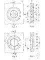
- the housing wall 10 of a commercially available circuit breaker has a first pre-marking 14 on the outer surface 12, which is assigned a second pre-marking 16 on the inner surface 18 of the housing 10.
- the second pre-marking 16, likewise formed as a recess is delimited on the outside by a cylindrical ring surface with the inside diameter Di and inside by a frustoconical ring surface tapering outwards with an inside diameter D 2 measured on the inside surface 18.
- Both pre-markings 14 and 16 are embossed so deeply that 20 rest is still in the form of an annular surface connecting the two pre-markings material remains.
- the outer diameter Di of the pre-marking 16 is smaller than the inner diameter D a of the recess 14, so that the annular surface 20 widens outwards like a truncated cone towards the outer surface 12.
- the annular surface 20 is the shortest connecting surface between the contour lines of the two depressions.
- a slot 22 is provided which receives a screwdriver, so that the wall part 24 formed by the projections 14 and 16 can be rotated and broken out of the wall 10 along the annular surface 20.
- the annular surface 20 thus forms a type of predetermined breaking point, along which the wall part 24 can be broken out to form an opening.
- the breakthrough that is formed is limited by the outer surface of the recess 16, which extends perpendicular to the surface 18 of the housing wall part 10, the frustoconical ring surface 20 and the outer surface of the recess 14. It can be seen from FIG.
- the outer diameter of the broken-out wall part 24 is larger than the inside diameter, ie here the smallest inside diameter of the opening, so that it is avoided with certainty that the wall part 24 falls into the interior of the housing, that is to say onto the left side of the housing 10 or the housing wall 10.
- the wall part 24 will basically remain outside the housing 10.
- the wall part 24 is rotated by means of a screwdriver which can be inserted into the slot 22.
- the wall part 30 to be broken out is formed by a pre-marking 32 designed as a recess, the inner contour 34 of which has the shape of a hexagon.
- the pre-marking on the opposite side is simply formed by a circular indentation 36, the depth T1 of which is selected so that the bottom surface 38 is beyond the inner one Ring surface 40 (bottom 40) of the pre-marking, which runs parallel to the outer surface 12, lies so that an annular area 42 of the smallest dimension is formed, which then serves as a predetermined breaking point, i.e.
- the wall part 30 is rotated by means of a hexagon socket wrench or, if appropriate, a hexagon ring wrench. It can be seen that the wrench size S of the wall part 30 or the diameter of the outermost circle, which surrounds the contour 34 and is equal to D a, is larger than the diameter D I of the recess 36, so that this also causes the broken-out wall part 30 to fall into it Interior of the housing is prevented.
- the inventive design of the housing walls at the relevant points ensures that the sections 24 and 30 can be broken out of the wall without fragments being able to get into the interior of the switch.
- the wall part 24 or 30 can be broken out by twisting, the dimensions of the broken-out part, i.e. the wall parts 24 or 30, being larger than the inside diameter of the breaking out of the wall part 24 or 30 remaining breakthrough.
- the pre-marking is generated during manufacture, that is to say the injection molding of the housing or the housing shell.
- manufacture that is to say the injection molding of the housing or the housing shell.
- configurations according to. 1 and 2 or 3 and 4 to combine, d. H. that is, to provide the slot 22 in the case of a hexagonal contour 34 and not to form the knockout 16 as shown in FIG. 2, that is to say in a wedge shape, but by means of a depression similar to that in FIG. 4.
Landscapes
- Engineering & Computer Science (AREA)
- Architecture (AREA)
- Civil Engineering (AREA)
- Structural Engineering (AREA)
- Casings For Electric Apparatus (AREA)
- Switch Cases, Indication, And Locking (AREA)
- Brushes (AREA)
- Input Circuits Of Receivers And Coupling Of Receivers And Audio Equipment (AREA)
- Dry Shavers And Clippers (AREA)
- Electrical Discharge Machining, Electrochemical Machining, And Combined Machining (AREA)
Priority Applications (1)
| Application Number | Priority Date | Filing Date | Title |
|---|---|---|---|
| AT83102880T ATE31128T1 (de) | 1982-04-01 | 1983-03-23 | Gehaeuse fuer ein elektrisches installationsgeraet. |
Applications Claiming Priority (2)
| Application Number | Priority Date | Filing Date | Title |
|---|---|---|---|
| DE3212064 | 1982-04-01 | ||
| DE19823212064 DE3212064A1 (de) | 1982-04-01 | 1982-04-01 | Gehaeuse fuer ein elektrisches installationsgeraet |
Publications (3)
| Publication Number | Publication Date |
|---|---|
| EP0091012A2 true EP0091012A2 (fr) | 1983-10-12 |
| EP0091012A3 EP0091012A3 (en) | 1986-11-05 |
| EP0091012B1 EP0091012B1 (fr) | 1987-11-25 |
Family
ID=6159928
Family Applications (1)
| Application Number | Title | Priority Date | Filing Date |
|---|---|---|---|
| EP83102880A Expired EP0091012B1 (fr) | 1982-04-01 | 1983-03-23 | Boîtier pour un appareil d'installation électrique |
Country Status (7)
| Country | Link |
|---|---|
| EP (1) | EP0091012B1 (fr) |
| AT (1) | ATE31128T1 (fr) |
| DE (1) | DE3212064A1 (fr) |
| ES (1) | ES271250Y (fr) |
| GB (1) | GB2118779B (fr) |
| PT (1) | PT76478B (fr) |
| ZA (1) | ZA831812B (fr) |
Cited By (2)
| Publication number | Priority date | Publication date | Assignee | Title |
|---|---|---|---|---|
| WO2013107485A1 (fr) * | 2011-12-20 | 2013-07-25 | Abb Ag | Découpe de flasque pré-estampée, élément structural ou partie de boîtier pourvu(e) d'une telle découpe de flasque, armoire électrique ou de distribution dotée d'un tel élément structural ou partie de boîtier, et système et procédé de pré-estampage de découpes de flasques |
| EP2360800A3 (fr) * | 2010-02-12 | 2013-08-28 | Kaiser GmbH & Co. KG | Elément d'installation |
Families Citing this family (3)
| Publication number | Priority date | Publication date | Assignee | Title |
|---|---|---|---|---|
| DE19913816A1 (de) * | 1999-03-26 | 2000-09-28 | Abb Patent Gmbh | Fehlerstromschutzschalter |
| JP6369982B2 (ja) * | 2014-07-22 | 2018-08-08 | ホシザキ株式会社 | 開閉扉の支持装置、開閉扉の組付け方法、及び、ピンホルダ |
| DE102015103900A1 (de) | 2015-03-17 | 2016-09-22 | Abb Ag | Gehäuse für ein elektrisches Installationsgerät |
Family Cites Families (4)
| Publication number | Priority date | Publication date | Assignee | Title |
|---|---|---|---|---|
| GB773193A (en) * | 1955-09-30 | 1957-04-24 | Chilton Aircraft Company Ltd | Improvements in and relating to electrical circuit-breakers |
| US3069517A (en) * | 1958-04-23 | 1962-12-18 | Fed Pacific Electric Co | Circuit breakers |
| DE1513584B2 (de) * | 1965-07-02 | 1970-05-21 | Stotz-Kontakt GmbH, 6800 Mannheim-Käfertal | Mehrpoliger Selbstschalter |
| DE7005827U (de) * | 1970-02-19 | 1970-05-21 | Bbc Brown Boveri & Cie | Selbstschalter mit isolierstoffgehaeuse. |
-
1982
- 1982-04-01 DE DE19823212064 patent/DE3212064A1/de not_active Withdrawn
-
1983
- 1983-03-16 ZA ZA831812A patent/ZA831812B/xx unknown
- 1983-03-23 AT AT83102880T patent/ATE31128T1/de not_active IP Right Cessation
- 1983-03-23 EP EP83102880A patent/EP0091012B1/fr not_active Expired
- 1983-03-30 ES ES1983271250U patent/ES271250Y/es not_active Expired
- 1983-03-30 PT PT76478A patent/PT76478B/pt unknown
- 1983-03-31 GB GB08308916A patent/GB2118779B/en not_active Expired
Cited By (2)
| Publication number | Priority date | Publication date | Assignee | Title |
|---|---|---|---|---|
| EP2360800A3 (fr) * | 2010-02-12 | 2013-08-28 | Kaiser GmbH & Co. KG | Elément d'installation |
| WO2013107485A1 (fr) * | 2011-12-20 | 2013-07-25 | Abb Ag | Découpe de flasque pré-estampée, élément structural ou partie de boîtier pourvu(e) d'une telle découpe de flasque, armoire électrique ou de distribution dotée d'un tel élément structural ou partie de boîtier, et système et procédé de pré-estampage de découpes de flasques |
Also Published As
| Publication number | Publication date |
|---|---|
| GB2118779B (en) | 1985-09-04 |
| EP0091012B1 (fr) | 1987-11-25 |
| DE3212064A1 (de) | 1983-10-06 |
| ATE31128T1 (de) | 1987-12-15 |
| GB8308916D0 (en) | 1983-05-11 |
| PT76478A (en) | 1983-04-01 |
| ZA831812B (en) | 1984-02-29 |
| PT76478B (en) | 1985-12-20 |
| ES271250U (es) | 1983-08-16 |
| ES271250Y (es) | 1984-03-16 |
| GB2118779A (en) | 1983-11-02 |
| EP0091012A3 (en) | 1986-11-05 |
Similar Documents
| Publication | Publication Date | Title |
|---|---|---|
| EP2839544B1 (fr) | Bornier de test | |
| EP0221839B1 (fr) | Interrupteur de puissance comportant un boîtier isolant à ouverture frontale et une plaquette de circuit | |
| DE202010008762U1 (de) | Elektrische Anschlussvorrichtung | |
| EP0091012B1 (fr) | Boîtier pour un appareil d'installation électrique | |
| EP0180008B1 (fr) | Elément fusible | |
| DE3807191A1 (de) | Schraubanschlussvorrichtung fuer elektrische leiter | |
| DE102004042427A1 (de) | Elektrisches Installationsgerät | |
| DE2920288B2 (de) | Schutzstecker für AnschluBblöcke | |
| DE2744074C2 (de) | Anschlußleiste für den Deckel eines elektrischen Gerätes | |
| EP0703641A2 (fr) | Elément de connecteur électrique | |
| EP0921611B1 (fr) | Prise et interrupteur pour le secteur | |
| EP0059939A1 (fr) | Borne pour le raccordement de fils électriques | |
| EP2430891A1 (fr) | Varistor enfichable | |
| DE112017007241B4 (de) | Auslöseschalter | |
| EP3201994A1 (fr) | Barrette à broches | |
| DE10061564B4 (de) | Anschlußeinheit für mehrpoligen Schalter | |
| DE19627971C2 (de) | BNC-Stecker | |
| DE19734234C2 (de) | Sicherung mit Kodierung | |
| EP3869645A1 (fr) | Couvercle de protection contre la manipulation pour un appareil de protection contre les surtensions destiné à l'installation sur un système de barre omnibus | |
| DE3220840C2 (de) | Druckfest gekapseltes, explosionsgeschütztes elektrisches Schaltgerät | |
| DE19612995C1 (de) | Kontaktstück und Verfahren zur Herstellung eines Kontaktstückes | |
| EP0833547A1 (fr) | Dispositif de signalisation lumineux | |
| DE2006083C3 (de) | Unterputzsteckdose | |
| DE29714132U1 (de) | Sicherung mit automatischer Kodierung | |
| DE3011762C2 (de) | Mehrpolige Kragensteckvorrichtung |
Legal Events
| Date | Code | Title | Description |
|---|---|---|---|
| PUAI | Public reference made under article 153(3) epc to a published international application that has entered the european phase |
Free format text: ORIGINAL CODE: 0009012 |
|
| AK | Designated contracting states |
Designated state(s): AT BE CH FR IT LI NL |
|
| PUAL | Search report despatched |
Free format text: ORIGINAL CODE: 0009013 |
|
| AK | Designated contracting states |
Kind code of ref document: A3 Designated state(s): AT BE CH FR IT LI NL |
|
| 17P | Request for examination filed |
Effective date: 19861211 |
|
| 17Q | First examination report despatched |
Effective date: 19870407 |
|
| GRAA | (expected) grant |
Free format text: ORIGINAL CODE: 0009210 |
|
| AK | Designated contracting states |
Kind code of ref document: B1 Designated state(s): AT BE CH FR IT LI NL |
|
| REF | Corresponds to: |
Ref document number: 31128 Country of ref document: AT Date of ref document: 19871215 Kind code of ref document: T |
|
| ITF | It: translation for a ep patent filed | ||
| ET | Fr: translation filed | ||
| PLBE | No opposition filed within time limit |
Free format text: ORIGINAL CODE: 0009261 |
|
| STAA | Information on the status of an ep patent application or granted ep patent |
Free format text: STATUS: NO OPPOSITION FILED WITHIN TIME LIMIT |
|
| 26N | No opposition filed | ||
| PG25 | Lapsed in a contracting state [announced via postgrant information from national office to epo] |
Ref country code: AT Effective date: 19890323 |
|
| PG25 | Lapsed in a contracting state [announced via postgrant information from national office to epo] |
Ref country code: LI Effective date: 19890331 Ref country code: CH Effective date: 19890331 Ref country code: BE Effective date: 19890331 |
|
| BERE | Be: lapsed |
Owner name: BOVERI & CIE A.G. Effective date: 19890331 Owner name: BROWN Effective date: 19890331 |
|
| PG25 | Lapsed in a contracting state [announced via postgrant information from national office to epo] |
Ref country code: NL Effective date: 19891001 |
|
| NLV4 | Nl: lapsed or anulled due to non-payment of the annual fee | ||
| PG25 | Lapsed in a contracting state [announced via postgrant information from national office to epo] |
Ref country code: FR Free format text: LAPSE BECAUSE OF NON-PAYMENT OF DUE FEES Effective date: 19891130 |
|
| REG | Reference to a national code |
Ref country code: CH Ref legal event code: PL |
|
| REG | Reference to a national code |
Ref country code: FR Ref legal event code: ST |