EP0091136A1 - Vorrichtung und Verfahren zum Biegen von dreieckigen Glasplatten - Google Patents
Vorrichtung und Verfahren zum Biegen von dreieckigen Glasplatten Download PDFInfo
- Publication number
- EP0091136A1 EP0091136A1 EP83104160A EP83104160A EP0091136A1 EP 0091136 A1 EP0091136 A1 EP 0091136A1 EP 83104160 A EP83104160 A EP 83104160A EP 83104160 A EP83104160 A EP 83104160A EP 0091136 A1 EP0091136 A1 EP 0091136A1
- Authority
- EP
- European Patent Office
- Prior art keywords
- triangular
- sections
- members
- edge
- glass
- Prior art date
- Legal status (The legal status is an assumption and is not a legal conclusion. Google has not performed a legal analysis and makes no representation as to the accuracy of the status listed.)
- Ceased
Links
- 239000011521 glass Substances 0.000 title claims abstract description 28
- 238000005452 bending Methods 0.000 title claims abstract description 9
- 238000000034 method Methods 0.000 title claims description 7
- 238000003825 pressing Methods 0.000 claims abstract description 8
- 239000011159 matrix material Substances 0.000 description 20
- 230000001681 protective effect Effects 0.000 description 8
- 239000007787 solid Substances 0.000 description 3
- XAGFODPZIPBFFR-UHFFFAOYSA-N aluminium Chemical compound [Al] XAGFODPZIPBFFR-UHFFFAOYSA-N 0.000 description 2
- 229910052782 aluminium Inorganic materials 0.000 description 2
- 239000004411 aluminium Substances 0.000 description 2
- 238000010276 construction Methods 0.000 description 2
- 239000000463 material Substances 0.000 description 2
- 240000007182 Ochroma pyramidale Species 0.000 description 1
- 239000005347 annealed glass Substances 0.000 description 1
- 238000006073 displacement reaction Methods 0.000 description 1
- 238000006467 substitution reaction Methods 0.000 description 1
Images


Classifications
-
- F—MECHANICAL ENGINEERING; LIGHTING; HEATING; WEAPONS; BLASTING
- F24—HEATING; RANGES; VENTILATING
- F24S—SOLAR HEAT COLLECTORS; SOLAR HEAT SYSTEMS
- F24S30/00—Arrangements for moving or orienting solar heat collector modules
- F24S30/40—Arrangements for moving or orienting solar heat collector modules for rotary movement
- F24S30/45—Arrangements for moving or orienting solar heat collector modules for rotary movement with two rotation axes
- F24S30/452—Vertical primary axis
-
- F—MECHANICAL ENGINEERING; LIGHTING; HEATING; WEAPONS; BLASTING
- F24—HEATING; RANGES; VENTILATING
- F24S—SOLAR HEAT COLLECTORS; SOLAR HEAT SYSTEMS
- F24S23/00—Arrangements for concentrating solar-rays for solar heat collectors
- F24S23/70—Arrangements for concentrating solar-rays for solar heat collectors with reflectors
- F24S23/71—Arrangements for concentrating solar-rays for solar heat collectors with reflectors with parabolic reflective surfaces
-
- F—MECHANICAL ENGINEERING; LIGHTING; HEATING; WEAPONS; BLASTING
- F24—HEATING; RANGES; VENTILATING
- F24S—SOLAR HEAT COLLECTORS; SOLAR HEAT SYSTEMS
- F24S25/00—Arrangement of stationary mountings or supports for solar heat collector modules
- F24S25/10—Arrangement of stationary mountings or supports for solar heat collector modules extending in directions away from a supporting surface
- F24S25/13—Profile arrangements, e.g. trusses
-
- Y—GENERAL TAGGING OF NEW TECHNOLOGICAL DEVELOPMENTS; GENERAL TAGGING OF CROSS-SECTIONAL TECHNOLOGIES SPANNING OVER SEVERAL SECTIONS OF THE IPC; TECHNICAL SUBJECTS COVERED BY FORMER USPC CROSS-REFERENCE ART COLLECTIONS [XRACs] AND DIGESTS
- Y02—TECHNOLOGIES OR APPLICATIONS FOR MITIGATION OR ADAPTATION AGAINST CLIMATE CHANGE
- Y02E—REDUCTION OF GREENHOUSE GAS [GHG] EMISSIONS, RELATED TO ENERGY GENERATION, TRANSMISSION OR DISTRIBUTION
- Y02E10/00—Energy generation through renewable energy sources
- Y02E10/40—Solar thermal energy, e.g. solar towers
- Y02E10/47—Mountings or tracking
Definitions
- This invention relates to a system and a method for bending plane sheets of glass so that they approximate to a curve.
- a paraboloid is an advantageous shape for a reflector as it has an inherent focusing capability, can be theoretically made quite large, and since it focuses on a point, instead of a line, can tolerate much greater focusing misalignment than other focusing reflectors.
- the design and construction of such a reflector is not as critical and hence generally less complex than other curved reflector systems, such as a trough system.
- parabolic reflecting surface from a single section of reflecting material, such as glass.
- An alternative to the single piece construction is the use of multiple sections.
- Parabolic reflectors have in fact previously been constructed from sections (see U.S. Patent No. 3618111 for example), but they have been impractical and inefficient, due to the geometry of the reflecting surface and the support structure therefore.
- a support structure for a large dimension parabolic reflector such as a solar reflector or the like, which comprises a plurality of triangular reflecting members which are relatively small in size compared to the size of the entire reflector and which conveniently are rigid, the support structure comprising one rigid support matrix comprising a plurality of strut-like members joined together at matrix joints to form a plurality of triangular sections arranged in a parabolic configuration, terminating in a rim which lies completely in a single plane; one set of standoff elements each connected to said one rigid support matrix at a respective one of said matrix joints and extending away from said one rigid support matrix; and means mounted on said standoff elements for securing said triangular reflecting members in position away from said one support matrix.
- a large dimension parabolic reflector apparatus comprising a first rigid support matrix comprising a plurality of strut-like members joined together at matrix joints to form a plurality of triangular sections arranged into a parabolic configuration, terminating at a rim which lies completely in a single plane; a plurality of triangular reflecting members which conveniently are rigid, arranged to form a parabolic reflector surface having approximately the configuration of said first rigid support matrix; a plurality of standoff elements connected at said matrix joints and at other points along said strut-like members; and means mounted on said standoff elements for supporting the triangular reflecting members in position away from said first rigid support matrix in such a manner that the triangular reflecting members form the parabolic reflector surface.
- parabolic reflector apparatus which includes a rigid support matrix having a plurality of strut-like members joined together in a geometric pattern, a plurality of reflecting members, and means on the support matrix for supporting said reflecting members on said support matrix in such an arrangement that said reflecting members form a substantially parabolic reflecting surface, the geometric pattern of said support matrix being characterised by the outline of a pentagon centered at a center of said support matrix.
- plane reflecting members can be used, instead of curved members. This is desirable, as the cost of plane sections of glass is considerably less than curved glass.
- slightly curved glass would reduce the number of sections in the reflector, and would also increase the operating temperature of the unit, if desirable. It would reduce the cost of curved glass considerably if plane glass could be bent, but it has been heretofore accepted that plane glass cannot be bent to produce a curved surface, i.e. that only a minimal displacement of plane glass can be achieved before breakage occurs.
- a system for bending substantially triangular plane sections of glass comprising means for supporting the triangular sections at each vertex thereof and means positioned along each edge of the triangular sections for applying pressure against that edge, forcing that edge into a configuration approaching a curve, so that the triangular section as a whole is curved.
- a method for bending substantially triangular plane sections of glass wherein the triangular sections include vertices and edges extending between said vertices comprising the steps of:
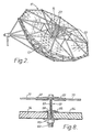
- Figures 1, 2 and 3 show parabolic reflector apparatus which includes a support framework 11 which comprises a number of elongated struts forming a plurality of triangular sections which together are arranged generally in the shape of a parabola.
- the support framework is spaced from a substantially parabolic reflecting surface by standoff supports positioned perpendicular to the reflecting surface, so that the geometry of the support framework 11 is such that the vertices of all the triangular sections lie substantially on the surface of an imaginary parabola.
- Backing surface 13 comprises a plurality of plane triangular sections, referred to as backing members, which are supported several centimetres (inches) off of support framework 11 by a number of different standoff elements which are not shown clearly in Figures 1 to 3 but which are shown in other figures and described in more detail in the description of my co-pending European Patent Application No. 80303000.6 (Publication No. EP-A-25320).
- Backing surface 13 generally follows the form of support framework 11.
- 4 equal size triangular backing members fit together and are arranged to be in registry with the outline of one of the secondary triangular sections comprising support framework 11.
- the backing members are solid and fit together to present a continuous surface interiorly of the support framework 11.
- the reflecting surface shown generally at 15, which comprises a plurality of triangular mirrored glass sections, referred to as reflecting members, is supported interiorly of the backing surface 13.
- Each reflecting member is supported at each vertex, and also at the midpoints of its 3 edges, by means of tensioning members connected to the backing surface 13, which are disclosed in detail hereinafter.
- the tensioning members bend the reflecting members so that they more closely resemble a curved surface.
- the reflecting members in the embodiment shown comprising the reflecting surface 15 are substantially the same size and are substantially in registry with the triangular backing members, comprising protective backing surface 13.
- the support framework 11 is visible, as is the solid protective backing surface 13, through the support framework.
- the reflecting surface 15, however, is not visible from the rear.
- the reflecting surface 15 is seen but not protective backing surface 13, nor support framework 11, as the glass sections comprising the reflecting surface form a substantially continuous surface.
- the support framework 11 terminates in a rim 17.
- a reflector face structure referred to generally at 19.
- the final portion of the reflector apparatus is the support carriage which is a rigid framework connected to opposite sides of the support framework 11. It holds the support framework 11, and hence the reflector apparatus as a whole, securely for rotation about 2 axes, the rotation about one axis permitting a change in attitude of the reflector, so that the reflector may follow a target from horizon to directly overhead to the horizon, while rotation about the other axis permits the reflector to be moved along a line at a given attitude.
- the support carriage may take one of many different forms to permit the necessary reflector movement in a given application.
- the particular form of support carriage 21 shown in the drawings by way of example, is described fully in the description of my co-pending European Patent Application No. 80303000.6 (Publication No. EP-A-25320) from which this application is divided.
- the reflector apparatus is particularly useful as a solar reflector, but it should be understood that the apparatus may be useful in other applications requiring large aperture parabolic reflectors.
- Figure 1 shows the support framework 11 of 'the reflector apparatus most clearly.
- the geometry of the framework is a significant aspect of the overall design of the parabolic reflector apparatus, and that geometry, together with the advantageous consequences, are described fully in the description of my co-pending European Patent Application No. 80303000.6 (Publication No. EP-A-25320) from which this application has been divided.
- the reflector apparatus shown in the drawings is approximately 9 metres (30 feet) in diameter and is approximately 3 metres (10 feet) deep.
- the focal point is at one-half of the depth so that it is half-way between the bottom of the framework 11 and the rim 17.
- the geometry for this pattern was produced by projecting the lower half of an icosahedron from a point on the axis of the reflector at a height of 3 metres (10 feet) from the bottom of the parabola.
- the depth and focal point of the reflector can be varied so that a shallower or deeper configured reflector can be produced. In some applications, a shallower configuration in particular may be desirable, as less glass, with a smaller curvature, is required for such a configuration.
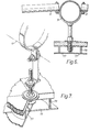
- the protective backing surface 13 is supported interiorly of the support framework 11 by the standoff elements, shown in Figures 4, 5, 6 and 7.
- the backing surface in the embodiment shown, comprises a plurality of triangular backing members sized and arranged so that 4 such backing members are in registry with each secondary triangular section of the support framework 11.
- a first type of standoff element is used at hubs 33, while a second standoff element is used at the intersection of the principal struts 31 and the secondary struts 41, and a third standoff element is used at the midpoint of the secondary struts 41.
- standoff elements shown are adapted for the embodiment shown, i.e. to support the backing surface, similar standoff elements could be used to directly support the reflecting surface.
- the position of the backing members relative to the struts may be easily adjusted at all of the standoff elements by adjustment of the nut and washer sets holding the vertices of the triangular backing members in place.
- the triangular backing members abut together at their edges, so that a continuous backing surface is formed, as explained above.
- the backing members being plane sections, like the triangular sections comprising the support framework, are a plane surface approximation of a parabola.
- the backing members in the embodiment shown, are triangular sections of balsa wood, approximately 6.35 mms. (one-quarter inch) thick, faced by aluminium sheets approximately 0.8 mms. (1/32 inch) thick, which results in a high strength, but relatively light, backing surface.
- the purpose of the backing surface is to provide protection for the reflecting surface portion of the apparatus, which is supported interiorly of the backing surface.
- the backing surface is thus located between the support framework and the reflecting surface. Hail and other wind borne debris would otherwise likely damage the reflecting surface without the backing surface.
- other protective surfaces are possible, such as for instance, sheet aluminium, which could be positioned on the exterior of the apparatus.
- the reflecting surface 15 comprises a plurality of triangular reflecting sections of mirrored glass, which, in the embodiment shown, have a size and configuration identical to the triangular backing members, and in fact are arranged so that they are in registry with the backing members. However, in other embodiments, it is possible that the reflecting members would be the same size as, and in registry with, the secondary triangular sections of the support framework 11.
- the reflecting members in the embodiment shown comprise plane sections of annealed glass approximately 23 mms. (0.09 inches) thick.
- the members are triangular and vary from 40 to 58 cms. (16 to 23 inches) on a side.
- the reflecting members are held in place by structure shown principally in Figure 9, and also in Figures 5, 6, 7 and 8.
- a collar 79 of plastic material approximately 7 1/2 cms. (3 inches) in diameter and 2 1/2 cms. (one inch) high. Collars 79 are not secured to the backing surface, although they could be in a given application.
- the reflecting members 77 are positioned so that the vertices of each member lie on the collar 79 and are supported thereby, as shown in Figure 9, with each reflecting member 77 being in registry with a corresponding backing member.
- the reflecting members 77 are held in place against the collars 79 at each vertex by tensioning members 81, shown in detail in Figure 8.
- Tensioning members 81 are located midway along each of the edges of the reflecting members 77, and extend from corresponding backing members, where they are fixedly positioned.
- the tensioning member includes a special rivet, which is threaded both on its inside and outside surfaces. Near the head end 83 of the rivet is positioned a washer and nut combination 85. Two abutting backing members 84 rest against the washer, while the rivet extends upwardly through the backing members. The edges of the backing members are cut out slightly to permit this. A threaded nut 86 holds the rivet in place relative to the backing members. A bolt 87 is threaded into the interior of the rivet at the other end 88 of the rivet sufficiently that approximately 2 1/2 cms. (an inch) of space exists between the head of bolt 87 and the other end 88 of the rivet.
- the temperature in a boiler at the focus of the reflector increases from approximately 427°C (800°F), for plane glass, to approximately 1093°C (2000°F), for curved glass. In some applications, however, this is not significant, as the temperature of the end energy should be 177°C to 288°C (350°F to 550°F) in many instances.
- the use of curved glass makes it possible to reduce the number of reflecting members by increasing their size, without detracting from the operation of the system. Thus, the use of curved glass does have advantages in certain applications. The system described above results in glass being bent to an extent previously thought not possible.
- a steam boiler may be added to the apparatus when the reflector is to be used as a solar collector.
- the boiler may take various configurations; one example is described and illustrated in my co-pending European Patent Application No. 79301473.9 (Publication No. EP-A-22887).
Landscapes
- Engineering & Computer Science (AREA)
- Chemical & Material Sciences (AREA)
- Life Sciences & Earth Sciences (AREA)
- Sustainable Development (AREA)
- Sustainable Energy (AREA)
- Thermal Sciences (AREA)
- Physics & Mathematics (AREA)
- Combustion & Propulsion (AREA)
- Mechanical Engineering (AREA)
- General Engineering & Computer Science (AREA)
- Aerials With Secondary Devices (AREA)
- Optical Elements Other Than Lenses (AREA)
- Non-Portable Lighting Devices Or Systems Thereof (AREA)
Applications Claiming Priority (2)
| Application Number | Priority Date | Filing Date | Title |
|---|---|---|---|
| US06/070,914 US4295709A (en) | 1979-08-29 | 1979-08-29 | Parabolic reflector comprising a plurality of triangular reflecting members forming a reflecting surface supported by a framework having a particular geometric pattern |
| US70914 | 1979-08-29 |
Related Parent Applications (1)
| Application Number | Title | Priority Date | Filing Date |
|---|---|---|---|
| EP80303000.6 Division | 1980-08-29 |
Publications (1)
| Publication Number | Publication Date |
|---|---|
| EP0091136A1 true EP0091136A1 (de) | 1983-10-12 |
Family
ID=22098133
Family Applications (2)
| Application Number | Title | Priority Date | Filing Date |
|---|---|---|---|
| EP80303000A Expired EP0025320B1 (de) | 1979-08-29 | 1980-08-29 | Parabolreflektor mit einer Vielzahl dreieckiger reflektierender Elemente |
| EP83104160A Ceased EP0091136A1 (de) | 1979-08-29 | 1980-08-29 | Vorrichtung und Verfahren zum Biegen von dreieckigen Glasplatten |
Family Applications Before (1)
| Application Number | Title | Priority Date | Filing Date |
|---|---|---|---|
| EP80303000A Expired EP0025320B1 (de) | 1979-08-29 | 1980-08-29 | Parabolreflektor mit einer Vielzahl dreieckiger reflektierender Elemente |
Country Status (4)
| Country | Link |
|---|---|
| US (1) | US4295709A (de) |
| EP (2) | EP0025320B1 (de) |
| AT (1) | ATE10231T1 (de) |
| DE (1) | DE3069601D1 (de) |
Cited By (1)
| Publication number | Priority date | Publication date | Assignee | Title |
|---|---|---|---|---|
| GB2165232A (en) * | 1984-09-19 | 1986-04-09 | Autoroofs Ltd | Curved vehicle window panels |
Families Citing this family (10)
| Publication number | Priority date | Publication date | Assignee | Title |
|---|---|---|---|---|
| US4750825A (en) * | 1980-01-07 | 1988-06-14 | Roxor Corporation | Segmented mirror |
| US4919527A (en) * | 1986-03-31 | 1990-04-24 | Nurmamed Saiylov | Solar radiation concentrator |
| ZA929953B (en) | 1991-12-24 | 1993-07-14 | David Hampton Mccloud | Caravan |
| GB2264790B (en) * | 1992-03-06 | 1995-06-28 | Ecovision Limited | Solar Cooker |
| US20080131830A1 (en) * | 2006-12-05 | 2008-06-05 | Nix Martin E | Use of renewable energy like solar, wind, geothermal, biomass, and hydropower for manufacturing combustion air for a fossil fuel burner and firebox |
| US20090065045A1 (en) * | 2007-09-10 | 2009-03-12 | Zenith Solar Ltd. | Solar electricity generation system |
| MX2008005063A (es) * | 2008-04-18 | 2009-10-19 | Univ Mexico Nacional Autonoma | Concentrador solar. |
| ES2609683T3 (es) * | 2008-06-06 | 2017-04-21 | Sunrise Csp Pty Limited | Mejoras en captadores térmicos solares |
| MX2010002418A (es) * | 2010-03-02 | 2011-09-15 | Univ Mexico Nacional Autonoma | Metodo y dispositivo de ajuste de posicion de espejos de un concentrador solar. |
| US9337544B2 (en) * | 2013-01-07 | 2016-05-10 | Lockheed Martin Corporation | Configurable backing structure for a reflector antenna and corrective synthesis for mechanical adjustment thereof |
Citations (5)
| Publication number | Priority date | Publication date | Assignee | Title |
|---|---|---|---|---|
| US2683334A (en) * | 1952-07-16 | 1954-07-13 | Ford Motor Co | Glass bending |
| US2707903A (en) * | 1951-04-11 | 1955-05-10 | Centre Nat Rech Scient | Composite mirrors of large area in particular for concentrating solar energy |
| FR2138711A1 (de) * | 1971-05-21 | 1973-01-05 | Glaverbel | |
| FR2138712A1 (de) * | 1971-05-21 | 1973-01-05 | Glaverbel | |
| US4018589A (en) * | 1976-01-22 | 1977-04-19 | Goodyear Aerospace Corporation | Glass shaping form mold |
Family Cites Families (14)
| Publication number | Priority date | Publication date | Assignee | Title |
|---|---|---|---|---|
| US1248456A (en) * | 1916-09-06 | 1917-12-04 | Paul L Clark | Projection-machine illumination. |
| US1386781A (en) * | 1918-09-07 | 1921-08-09 | Harvey Walter James | Solar motor |
| FR1035832A (fr) * | 1951-04-11 | 1953-08-31 | Centre Nat Rech Scient | Dispositif permettant la concentration d'énergie solaire à l'aide de surfaces réfléchissantes déformées mécaniquement |
| US2987961A (en) * | 1958-04-17 | 1961-06-13 | Eugene S Cotton | Solar furnace |
| NL289975A (de) * | 1962-03-08 | |||
| US3618111A (en) * | 1967-04-28 | 1971-11-02 | Gen Dynamics Corp | Expandable truss paraboloidal antenna |
| FR2112013B1 (de) * | 1970-04-29 | 1974-10-31 | Camusat Gueguen France | |
| JPS49119556A (de) * | 1973-02-16 | 1974-11-15 | ||
| US3977773A (en) * | 1975-01-17 | 1976-08-31 | Rohr Industries, Inc. | Solar energy concentrator |
| FR2349011A1 (fr) * | 1976-04-20 | 1977-11-18 | Baratcabal Pierre | Installation de surfaces dont la morphologie(matrice)est liee a la fonction par un rapport geometrique(par exemple optique:miroir,etc.) |
| JPS52148324A (en) * | 1976-06-04 | 1977-12-09 | Suwa Seikosha Kk | Miniature printer |
| US4171876A (en) * | 1977-10-17 | 1979-10-23 | Wood Douglas E | Apparatus for supporting large-dimension curved reflectors |
| US4161942A (en) * | 1977-12-27 | 1979-07-24 | Monk Robert J | Solar energy collector |
| ATE5670T1 (de) * | 1979-07-24 | 1984-01-15 | Douglas E. Wood | Stuetzwerk fuer einen parabolischen reflektor grosser dimension und parabolischer reflektor grosser dimension. |
-
1979
- 1979-08-29 US US06/070,914 patent/US4295709A/en not_active Expired - Lifetime
-
1980
- 1980-08-29 DE DE8080303000T patent/DE3069601D1/de not_active Expired
- 1980-08-29 EP EP80303000A patent/EP0025320B1/de not_active Expired
- 1980-08-29 AT AT80303000T patent/ATE10231T1/de not_active IP Right Cessation
- 1980-08-29 EP EP83104160A patent/EP0091136A1/de not_active Ceased
Patent Citations (5)
| Publication number | Priority date | Publication date | Assignee | Title |
|---|---|---|---|---|
| US2707903A (en) * | 1951-04-11 | 1955-05-10 | Centre Nat Rech Scient | Composite mirrors of large area in particular for concentrating solar energy |
| US2683334A (en) * | 1952-07-16 | 1954-07-13 | Ford Motor Co | Glass bending |
| FR2138711A1 (de) * | 1971-05-21 | 1973-01-05 | Glaverbel | |
| FR2138712A1 (de) * | 1971-05-21 | 1973-01-05 | Glaverbel | |
| US4018589A (en) * | 1976-01-22 | 1977-04-19 | Goodyear Aerospace Corporation | Glass shaping form mold |
Cited By (1)
| Publication number | Priority date | Publication date | Assignee | Title |
|---|---|---|---|---|
| GB2165232A (en) * | 1984-09-19 | 1986-04-09 | Autoroofs Ltd | Curved vehicle window panels |
Also Published As
| Publication number | Publication date |
|---|---|
| EP0025320B1 (de) | 1984-11-07 |
| DE3069601D1 (en) | 1984-12-13 |
| US4295709A (en) | 1981-10-20 |
| EP0025320A3 (en) | 1981-09-09 |
| ATE10231T1 (de) | 1984-11-15 |
| EP0025320A2 (de) | 1981-03-18 |
Similar Documents
| Publication | Publication Date | Title |
|---|---|---|
| US4171876A (en) | Apparatus for supporting large-dimension curved reflectors | |
| AU2009251196B2 (en) | Carrier for a solar energy reflector element | |
| US4487196A (en) | Focusing solar collector and method for manufacturing same | |
| US4611575A (en) | Parabolic trough solar reflector | |
| US4743095A (en) | Clip fasteners for parabolic dish reflector panels | |
| EP0091136A1 (de) | Vorrichtung und Verfahren zum Biegen von dreieckigen Glasplatten | |
| US9006560B2 (en) | Solar receiver | |
| US4313422A (en) | Collapsible structural assembly especially suitable as a solar concentrator | |
| WO2005003646A1 (en) | Carrier and drive arrangement for a solar energy reflector system | |
| ZA200306717B (en) | Solar energy reflector array. | |
| US20110168260A1 (en) | Reflective polyhedron optical collector and method of using the same | |
| US20050225885A1 (en) | Method and apparatus for constructing a perfect trough parabolic reflector | |
| US4281900A (en) | Frontal reflector bracing | |
| US4596238A (en) | Interiorly tensioned solar reflector | |
| US8186340B2 (en) | Score and form solar reflector | |
| US4372772A (en) | Parabolic reflector comprising a plurality of triangular reflecting members forming a reflecting surface supported by a framework having a particular geometric pattern | |
| US4501469A (en) | Mirror structure for reflecting and concentrating radiation energy | |
| US4416263A (en) | High ratio solar energy linear type concentrating collector | |
| EP0022887B1 (de) | Stützwerk für einen parabolischen Reflektor grosser Dimension und parabolischer Reflektor grosser Dimension | |
| EP1831615B1 (de) | Reflektoranordnung für energiekonzentratoren | |
| US4841305A (en) | Method of sectioning an antennae reflector | |
| CN113188262A (zh) | 一种定日镜镜架 | |
| US20090251811A1 (en) | Method and Apparatus for Constructing a Perfect Trough Parabolic Reflector | |
| JPH01503670A (ja) | ハブおよびリム反射器 | |
| US20030210483A1 (en) | Method and apparatus for constructing a perfect trough parabolic reflector |
Legal Events
| Date | Code | Title | Description |
|---|---|---|---|
| PUAI | Public reference made under article 153(3) epc to a published international application that has entered the european phase |
Free format text: ORIGINAL CODE: 0009012 |
|
| AC | Divisional application: reference to earlier application |
Ref document number: 25320 Country of ref document: EP |
|
| AK | Designated contracting states |
Designated state(s): AT BE CH DE FR GB IT LI LU NL SE |
|
| 17P | Request for examination filed |
Effective date: 19831219 |
|
| STAA | Information on the status of an ep patent application or granted ep patent |
Free format text: STATUS: THE APPLICATION HAS BEEN REFUSED |
|
| 18R | Application refused |
Effective date: 19881013 |