EP0091147A2 - Vorrichtung zum Aufstreichen einer Substanz auf ein bandförmiges Material - Google Patents
Vorrichtung zum Aufstreichen einer Substanz auf ein bandförmiges Material Download PDFInfo
- Publication number
- EP0091147A2 EP0091147A2 EP83200380A EP83200380A EP0091147A2 EP 0091147 A2 EP0091147 A2 EP 0091147A2 EP 83200380 A EP83200380 A EP 83200380A EP 83200380 A EP83200380 A EP 83200380A EP 0091147 A2 EP0091147 A2 EP 0091147A2
- Authority
- EP
- European Patent Office
- Prior art keywords
- spreading
- bar
- rotary bar
- extrusion head
- flow slot
- Prior art date
- Legal status (The legal status is an assumption and is not a legal conclusion. Google has not performed a legal analysis and makes no representation as to the accuracy of the status listed.)
- Withdrawn
Links
Images
Classifications
-
- B—PERFORMING OPERATIONS; TRANSPORTING
- B05—SPRAYING OR ATOMISING IN GENERAL; APPLYING FLUENT MATERIALS TO SURFACES, IN GENERAL
- B05C—APPARATUS FOR APPLYING FLUENT MATERIALS TO SURFACES, IN GENERAL
- B05C5/00—Apparatus in which liquid or other fluent material is projected, poured or allowed to flow on to the surface of the work
- B05C5/02—Apparatus in which liquid or other fluent material is projected, poured or allowed to flow on to the surface of the work the liquid or other fluent material being discharged through an outlet orifice by pressure, e.g. from an outlet device in contact or almost in contact, with the work
- B05C5/0254—Coating heads with slot-shaped outlet
- B05C5/0266—Coating heads with slot-shaped outlet adjustable in length, e.g. for coating webs of different width
-
- B—PERFORMING OPERATIONS; TRANSPORTING
- B05—SPRAYING OR ATOMISING IN GENERAL; APPLYING FLUENT MATERIALS TO SURFACES, IN GENERAL
- B05C—APPARATUS FOR APPLYING FLUENT MATERIALS TO SURFACES, IN GENERAL
- B05C11/00—Component parts, details or accessories not specifically provided for in groups B05C1/00 - B05C9/00
- B05C11/02—Apparatus for spreading or distributing liquids or other fluent materials already applied to a surface ; Controlling means therefor; Control of the thickness of a coating by spreading or distributing liquids or other fluent materials already applied to the coated surface
- B05C11/023—Apparatus for spreading or distributing liquids or other fluent materials already applied to a surface
- B05C11/025—Apparatus for spreading or distributing liquids or other fluent materials already applied to a surface with an essentially cylindrical body, e.g. roll or rod
-
- B—PERFORMING OPERATIONS; TRANSPORTING
- B05—SPRAYING OR ATOMISING IN GENERAL; APPLYING FLUENT MATERIALS TO SURFACES, IN GENERAL
- B05C—APPARATUS FOR APPLYING FLUENT MATERIALS TO SURFACES, IN GENERAL
- B05C5/00—Apparatus in which liquid or other fluent material is projected, poured or allowed to flow on to the surface of the work
- B05C5/02—Apparatus in which liquid or other fluent material is projected, poured or allowed to flow on to the surface of the work the liquid or other fluent material being discharged through an outlet orifice by pressure, e.g. from an outlet device in contact or almost in contact, with the work
- B05C5/0254—Coating heads with slot-shaped outlet
- B05C5/0262—Coating heads with slot-shaped outlet adjustable in width, i.e. having lips movable relative to each other in order to modify the slot width, e.g. to close it
-
- B—PERFORMING OPERATIONS; TRANSPORTING
- B05—SPRAYING OR ATOMISING IN GENERAL; APPLYING FLUENT MATERIALS TO SURFACES, IN GENERAL
- B05C—APPARATUS FOR APPLYING FLUENT MATERIALS TO SURFACES, IN GENERAL
- B05C3/00—Apparatus in which the work is brought into contact with a bulk quantity of liquid or other fluent material
- B05C3/18—Apparatus in which the work is brought into contact with a bulk quantity of liquid or other fluent material only one side of the work coming into contact with the liquid or other fluent material
Definitions
- the present invention relates to a device for spreading a substance on a ribbon material which advances supported by a roller, comprising a rotating bar arranged in contact with the ribbon material in correspondence with said roller, and an extrusion head with a slot flow rate to feed the substance to be spread to the rotary bar.
- the means for feeding the substance to be spread is formed by an extrusion head with flow slot and the rotary bar is mounted in the same extrusion head, in the outlet of the slot of debt.
- spreading is normally done over a width corresponding to the entire extension of the rotary bar and the extrusion head.
- profiled limiters To modify the width of the spreading it is necessary to insert profiled limiters so that they adhere to the surface of the bar, to seal both in the flow slot and against the bar which is introduced therein. This involves a harmful friction but, above all, the execution of the operation is long and difficult, particular when working at high temperatures such as 200 - 300 ° C, and the results are not always flawless.
- the limitation strips supported by external limiters cannot be used, which are used in heads for direct extrusion for occluding part of the flow slot. Furthermore, in such devices, even in cases where effective partitioning of the flow slot could be achieved, it would still generally be necessary to employ a tape support roll having an operating surface of exactly the width corresponding to the spreading width, to avoid harmful direct dry friction contact between the rotating bar and the roller. Consequently, to move from spreading a strip of a given width to spreading a strip of different width, it would also be necessary to replace the roll with another roll having different characteristics, which would require having an assortment of rollers of high price and size as well as performing a relatively long and expensive conversion operation of the device.
- the main object of the present invention is to provide a spreading device, of the type indicated in the preamble, which can be adapted to carry out spreading over an adjustable width, by a relatively short operation and of easy execution and without requiring the availability of expensive assortments of parts.
- the partialization means constituted by lamella segments which exactly fill the outlet part of the flow slot up to the external surface of the extrusion head, provide an exact delimitation of the flow zones of the substance to be spread, which can then correspond exactly to the desired spreading width.
- the presence of the lamella head, introduced into the corresponding cavity of the flow slot, allows the limiting lamella segments to resist the extrusion pressure and effect effective closing in the areas where spreading should not be carried out.
- the limitation of the operative surface of the bar to the areas where the spreading must be carried out prevents any direct dry friction contact between the rotary bar and the roll of support for the material in tape, so that the roll, having a width corresponding to that of the extrusion head, does not require to be replaced or modified to work correctly on reduced widths.
- the mounting of the rotating bar in an organ support separate from the extrusion head and applied thereto ensures the possibility of independently carrying out the adjustments of the flow slot and of the rotary bar, and furthermore it makes possible the adoption of means for imposing on the rotating bar perfect parallelism with respect to the opposite generatrix of the tape support roller, with compensation for elastic deformation arrows due to the weight of the parts and the forces involved, thus ensuring exact uniformity of the thickness of the spread substance on the ribbon material and, consequently, even the possibility of reducing this thickness to the minimum admissible values, with the consequent reduction in consumption of the spread substance.
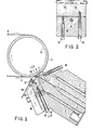
- the spreading device illustrated in FIG. 1 comprises an extrusion head formed by two juxtaposed parts 1 and 2, each of which advances to form an extrusion lip, respectively 3 and 4, which in this case is of a single piece with the parts of the head but which, in known manner, could be postponed. Between the two parts 1 and 2 of the head is formed a supply conduit 5 intended to be supplied, by an extruder or by a pump not shown, with the substance to be spread, warmed in the molten state or, by its nature , fluid at room temperature.
- the supply duct 5 opens into a manifold 6 which extends over the entire width of the head 1 - 2 and from which begins a flow slot 7 which extends to the outlet part 8 between the two lips extrusion 3 and 4, the lip 3 of which is flexible.
- the opening of the flow slot 7 can be adjusted by means of screws 10 screwed into the body 1 of the head and which act on the lip 3 which deforms by flexibility.
- the outlet 8 of the flow slot 7 is placed opposite a hollow roller 13 on which passes and rests the tape 0 which must be coated in a thin layer with the substance fed through the conduit 5.
- the tape 0 advances at a speed which can be, for example, from 30 to 500 meters per minute.
- the roller 13 can be, depending on operational requirements, refrigerated or even slightly warmed and thermostatically controlled. It is usually coated, in a way known, with silicone rubber or other material having limited flexibility, for example with a hardness of 80 to 95 Shore.
- the flow slot 7, very close upstream of its outlet part 8, forms a profiled cavity 9 which extends over the entire width of the extrusion head.
- the operating width of the extrusion head is limited by introducing, into the outlet part 8 of the extrusion slot 7, segments of a limiting strip 11, having a thickness corresponding to the desired opening. from the flow slot, and ending at the inner end with a head 12 suitable for occupying part of the cavity 9 of the flow slot 7.
- the lamella segments 11 are introduced, from the ends, into the parts of the flow slot 7 that we want to neutralize to the effects of spreading, leaving free a central zone of width corresponding to the spreading width to be produced.
- the head 12 of each lamella segment 11 thus occludes the cavity 9 in the corresponding parts of the flow slot 7, providing an effective seal capable of withstanding the pressure of the molten substance supplied by the extruder or the pump, without require no outside support.
- the strip 11 also occupies the corresponding parts of the outlet 8 of the flow slot 7, pressed by the screws 10, thereby correctly delimiting the active part of the flow slot until the outlet and ensuring an exact and effective lateral tightness .
- the outlet itself can be arranged near a spreading bar placed in contact with the tape 0 and rotating in a direction consistent with the movement of the tape, to receive the substance which leaves the flow slot and transport it on the ribbon.
- the distance between the outlet of the flow slot and the point of application of the substance on the tape can vary according to the diameter of the rotary bar and its arrangement, and it can thus be established, for example, between 4 and 15 mm. This distance is of considerable importance for the proper functioning of the device, because it allows a stretching of the spread substance and, consequently, an appropriate reduction of its thickness from the value corresponding to the width of the flow slit to an adequate lower value. .
- the extrusion head has a raised part 15 (which in other embodiments can be constructively separated and fixed to the head) to which, by means of traction screws 16 alternating with screws pressure 17, is united a block 18 which can be blocked by stirrups 19 fixed to the body 2 of the head by screws 20.
- these arrows can be of some tenth of a millimeter, in relation to the width of the extrusion head which can vary, for example, from 300 to 3000 mm. These arrows are large in relation to the thickness, which can be for example 5 to 20 microns, of the layer of substance to be spread.
- the adjusted position of the block 18 and of the rotary bar 22 is fixed by tightening the screws 20 and therefore the stirrups 19.
- the above adjustment is carried out so that the rotating bar 22 is supported in a more timely manner on the tape 0, supported by the roller 13, and intended to receive a thin layer of the extruded substance which leaves the flow slot.
- the extruded substance is thus immediately spread on the tape 0 with the possibility of obtaining perfect uniformity of thickness, even when working over large widths. It should be noted that the application of such a bar immediately downstream of the outlet of the flow slot would be impossible in known extrusion heads with variable operating width, in which the limiters have a considerable bulk in correspondence with the non-active parts of the outlet of the flow slot.
- the bar 22 is kept in rotation by means 29 in the direction (contrary to that of the needles of a watch according to FIG. 1) which carries towards the ribbon 0 the substance leaving the flow slot S.
- the bar is actuated at a tangential speed much lower than that of the roller 13 and the tape 0, for example, from 1:10 to 1: 100 of it, so that when passing from the surface of the bar to the surface of the tape, the substance spread out undergoes a stretch and forms a very thin layer.
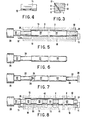
- the bar 22 is worked, as shown in FIG. 5, so that it has its active surface limited to the areas where the spreading takes place.
- the remaining zones 30, 31 of the surface of the bar are hollowed out so that they do not come into contact with the roller 13 facing them.
- the transition points from the operating surface 22 to the non-operating surfaces 30 and 31 of the bar correspond to the limits of the lamella segments 11 inserted in the adjacent flow slot 1 - 8, so that the extruded substance is delivered exclusively in correspondence of the operating surfaces 22 of the bar, and transported on the tape 0 which is pressed against the roller 13.
- the latter does not cannot come into contact with the non-operative areas of the bar because of their digging, and no harmful contact can be verified although the roller 13 always has a width corresponding to the entire width of the extrusion head.
- the digging of the parts 30 and 31 relative to the operating surface of the bar 22 must be such as to prevent contact of the bar with the roll 13, and it therefore mainly depends on the thickness of the tape material 0, as well as the surface hardness of the coating of the roller 13 and the diameter of the bar 22.
- the digging of the bar in the non-operative parts can be 0.3 to 1 mm.
- the bars 22 having hollowed out parts could not be installed in known devices, that is to say directly in the outlet of the flow slot of the extrusion head, since in such a case the substances debited would flow uncontrollably between the seat and the hollowed out areas of the bar making operation impossible.
- the bar 22 must be replaced by another bar having the hollowed parts arranged differently or of different length, when the spreading width is modified, namely, when the arrangement is modified limiting strips 11 in the flow slot.
- keeping an assortment of bars 22 in store represents a space and costs far lower than those of the conservation of an assortment of rollers 13 and, moreover, the operation of replacing the bar 22 is extremely easier and quicker than the replacement of the roller 13, and consequently involves a good downtime of the machine inferior.
- the hollowed-out part 30 of the bar 22, according to FIG. 5, is necessary for the connection of the bar even to the actuating mandrel 29, while the hollowed-out part 31 is inactive and, as shown in FIG. 6, it can be also deleted.
- the bars 22 must be manufactured with special steels or subjected to special treatments, for example nitriding, which make them relatively expensive materials, so that it is advantageous to reduce the bars 22 to the least possible length.
- the bar 22 can be reduced to the sole length of its operative part, as shown in FIG. 7.
- a connection bar 32 is connected to the actuating mandrel and it s' extends with a hollowed portion 33 up to the coupling means engaged in one end of the bar 22; the coupling means may consist of a flattened or prismatic part 34 of the connection bar 32 inserted in a corresponding cavity of the bar 22, and by a centering pivot 35.
- the connection bar 32 thus serves as a transmission for the bar 22.
- the opposite end of the bar 22 is pressed against the convex end 36 of a spacer bar 37, pressed at the outer end against a fixed part 38.
- the spacer bar 37 does not rotate and it only has the function of ensuring the maintenance of a correct transverse position of the stage bar also 22.
- the bar 22 has a plurality of operative parts separated from one another by hollow parts 39, 40, 41 which are added to the hollowed end parts 30 and 31 In correspondence with each hollowed out portion, a segment of lamella 11 is inserted into the flow slot of the extrusion head. It is well understood that this arrangement, unthinkable in known devices, produces the flow and spreading of the extruded substance along strips separated from the tape 0.
- the arrangement can be used either for spreading with strips, separated by non-spreading zones, on a single strip 0, or even for performing a spreading simultaneously on several strips of reduced width, arranged side by side.
- FIGS. 6 and 7 which have the aim of reducing the cost price of the bar 22, can also be applied in the case of a bar 22 having several intermediate hollowed parts 39, 40, 41 according to the figure 8.
- the device according to the invention can be used either hot, for spreading molten substances, up to temperatures of the order of 330 ° C., or at ambient temperature, for spreading substances having such a viscosity that they must not be melted to carry out the spreading.
- the extrusion head is oriented towards the roller on which the ribbon passes, and its main direction (longitudinal) is inclined about 30 ° below the horizontal; this provision has been shown to be most appropriate in many cases.
- the inclination of the extrusion head can be modified, for example from 15 ° to 45 °, according to the viscosity of the substance to be spread and according to the installation requirements and the characteristics of other elements of the spread group.
- the inclination of the spreading head is particularly advantageous in hot work, because in the event of work interruption the roller 13 can be lifted with the ribbon 0, adjust the speed of the bar 22 to a minimum and reduce at a minimum the flow of the substance to be spread, which then continues to be supplied in small quantities and is carried away by the bar, then drains along block 21, without stationing in the device, which would cause decompositions and obstructions.
- a protective plate 28 is applied, over the entire width of the extrusion head, to the block 21, as shown in FIG. 1, to guide the substance which leaves beyond the 'size of the parts united to the extrusion head, and allow to collect it in a basin without producing stains.
Landscapes
- Coating Apparatus (AREA)
- Extrusion Moulding Of Plastics Or The Like (AREA)
- Preliminary Treatment Of Fibers (AREA)
Applications Claiming Priority (2)
| Application Number | Priority Date | Filing Date | Title |
|---|---|---|---|
| IT6744282 | 1982-04-05 | ||
| IT8267442A IT8267442A0 (it) | 1982-04-05 | 1982-04-05 | Dispositivo per spalmare una sostanza su di un materiale in nastro |
Publications (2)
| Publication Number | Publication Date |
|---|---|
| EP0091147A2 true EP0091147A2 (de) | 1983-10-12 |
| EP0091147A3 EP0091147A3 (de) | 1985-08-07 |
Family
ID=11302420
Family Applications (1)
| Application Number | Title | Priority Date | Filing Date |
|---|---|---|---|
| EP83200380A Withdrawn EP0091147A3 (de) | 1982-04-05 | 1983-03-21 | Vorrichtung zum Aufstreichen einer Substanz auf ein bandförmiges Material |
Country Status (4)
| Country | Link |
|---|---|
| US (1) | US4465015A (de) |
| EP (1) | EP0091147A3 (de) |
| ES (1) | ES520764A0 (de) |
| IT (1) | IT8267442A0 (de) |
Cited By (4)
| Publication number | Priority date | Publication date | Assignee | Title |
|---|---|---|---|---|
| EP0152921A3 (en) * | 1984-02-20 | 1986-12-10 | John Mladota | Coating device for sheetlike materials |
| GB2227959A (en) * | 1989-01-17 | 1990-08-15 | Valmet Paper Machinery Inc | Blade coating a material web |
| EP0347736A3 (en) * | 1988-06-21 | 1990-09-26 | British United Shoe Machinery Limited | Adhesive-applying apparatus |
| EP0887115A3 (de) * | 1997-05-27 | 1999-05-19 | BemaTec SA | Beschichtung poröser Träger |
Families Citing this family (44)
| Publication number | Priority date | Publication date | Assignee | Title |
|---|---|---|---|---|
| FI853041A0 (fi) * | 1985-08-07 | 1985-08-07 | Valmet Oy | Anordning foer belaeggning av materialbana. |
| DE3721593A1 (de) * | 1987-06-30 | 1989-01-26 | Henning J Claassen | Vorrichtung zum auftragen von fluessigen klebstoffen auf ein substrat |
| US4899691A (en) * | 1987-07-09 | 1990-02-13 | Bolton-Emerson, Inc. | Precision positioning system for a coater |
| MX170005B (es) * | 1987-07-09 | 1993-08-04 | Bolton Emerson | Sistema de colocadores de precision |
| SE467528B (sv) * | 1988-09-27 | 1992-08-03 | Btg Kaelle Inventing Ab | Anordning foer bestrykning av en loepande bana |
| FI88421C (fi) * | 1990-04-19 | 1993-05-10 | Valmet Paper Machinery Inc | Bestrykningsanordning foer bestrykning av vals i en limpress, papper eller kartong |
| US5259307A (en) * | 1991-05-10 | 1993-11-09 | Illinois Tool Works Inc. | Registration adjustment for rotary screen printing apparatus |
| CA2122089A1 (en) * | 1993-04-30 | 1994-10-31 | Glen H. Bayer, Jr. | Method and apparatus for applying a coating material to a receiving surface |
| US5747107A (en) * | 1995-10-26 | 1998-05-05 | Minnesota Mining And Manufacturing Company | Method of applying a hot melt coating |
| US20020121239A1 (en) * | 1996-04-10 | 2002-09-05 | Tonazzi Juan C. Lopez | Devices and methods for applying liquid coatings to substrates |
| US6803076B2 (en) | 2002-04-16 | 2004-10-12 | 3M Innovative Properties Company | Die lip for strip coating |
| US7591903B2 (en) * | 2002-08-13 | 2009-09-22 | 3M Innovative Properties Company | Die having multiple orifice slot |
| DE10323213B4 (de) * | 2003-05-22 | 2006-02-23 | Thyssen Polymer Gmbh | Vorrichtung zum Kaschieren von Profilen |
| WO2005033407A1 (en) * | 2003-10-09 | 2005-04-14 | Btg Umv Coating Systems Aktiebolag | Holder for rod cradle for revolving coating rod |
| US7775966B2 (en) | 2005-02-24 | 2010-08-17 | Ethicon Endo-Surgery, Inc. | Non-invasive pressure measurement in a fluid adjustable restrictive device |
| US7699770B2 (en) | 2005-02-24 | 2010-04-20 | Ethicon Endo-Surgery, Inc. | Device for non-invasive measurement of fluid pressure in an adjustable restriction device |
| US7775215B2 (en) | 2005-02-24 | 2010-08-17 | Ethicon Endo-Surgery, Inc. | System and method for determining implanted device positioning and obtaining pressure data |
| US7927270B2 (en) | 2005-02-24 | 2011-04-19 | Ethicon Endo-Surgery, Inc. | External mechanical pressure sensor for gastric band pressure measurements |
| US8066629B2 (en) | 2005-02-24 | 2011-11-29 | Ethicon Endo-Surgery, Inc. | Apparatus for adjustment and sensing of gastric band pressure |
| US7658196B2 (en) | 2005-02-24 | 2010-02-09 | Ethicon Endo-Surgery, Inc. | System and method for determining implanted device orientation |
| US8016744B2 (en) | 2005-02-24 | 2011-09-13 | Ethicon Endo-Surgery, Inc. | External pressure-based gastric band adjustment system and method |
| US8152710B2 (en) | 2006-04-06 | 2012-04-10 | Ethicon Endo-Surgery, Inc. | Physiological parameter analysis for an implantable restriction device and a data logger |
| US8870742B2 (en) | 2006-04-06 | 2014-10-28 | Ethicon Endo-Surgery, Inc. | GUI for an implantable restriction device and a data logger |
| US8187163B2 (en) | 2007-12-10 | 2012-05-29 | Ethicon Endo-Surgery, Inc. | Methods for implanting a gastric restriction device |
| US8100870B2 (en) | 2007-12-14 | 2012-01-24 | Ethicon Endo-Surgery, Inc. | Adjustable height gastric restriction devices and methods |
| US8377079B2 (en) | 2007-12-27 | 2013-02-19 | Ethicon Endo-Surgery, Inc. | Constant force mechanisms for regulating restriction devices |
| US8142452B2 (en) | 2007-12-27 | 2012-03-27 | Ethicon Endo-Surgery, Inc. | Controlling pressure in adjustable restriction devices |
| US8591395B2 (en) | 2008-01-28 | 2013-11-26 | Ethicon Endo-Surgery, Inc. | Gastric restriction device data handling devices and methods |
| US8337389B2 (en) | 2008-01-28 | 2012-12-25 | Ethicon Endo-Surgery, Inc. | Methods and devices for diagnosing performance of a gastric restriction system |
| US8192350B2 (en) | 2008-01-28 | 2012-06-05 | Ethicon Endo-Surgery, Inc. | Methods and devices for measuring impedance in a gastric restriction system |
| US8221439B2 (en) | 2008-02-07 | 2012-07-17 | Ethicon Endo-Surgery, Inc. | Powering implantable restriction systems using kinetic motion |
| US7844342B2 (en) | 2008-02-07 | 2010-11-30 | Ethicon Endo-Surgery, Inc. | Powering implantable restriction systems using light |
| US8114345B2 (en) | 2008-02-08 | 2012-02-14 | Ethicon Endo-Surgery, Inc. | System and method of sterilizing an implantable medical device |
| US8057492B2 (en) | 2008-02-12 | 2011-11-15 | Ethicon Endo-Surgery, Inc. | Automatically adjusting band system with MEMS pump |
| US8591532B2 (en) | 2008-02-12 | 2013-11-26 | Ethicon Endo-Sugery, Inc. | Automatically adjusting band system |
| US8034065B2 (en) | 2008-02-26 | 2011-10-11 | Ethicon Endo-Surgery, Inc. | Controlling pressure in adjustable restriction devices |
| US8187162B2 (en) | 2008-03-06 | 2012-05-29 | Ethicon Endo-Surgery, Inc. | Reorientation port |
| US8233995B2 (en) | 2008-03-06 | 2012-07-31 | Ethicon Endo-Surgery, Inc. | System and method of aligning an implantable antenna |
| TWI588226B (zh) | 2011-10-19 | 2017-06-21 | 3M新設資產公司 | 具有薄熔體塗覆之物件及彼等之製造方法 |
| WO2015100319A1 (en) | 2013-12-26 | 2015-07-02 | 3M Innovative Properties Company | Adhesive tapes and methods for making |
| SG11201705178SA (en) | 2014-12-23 | 2017-07-28 | 3M Innovative Properties Co | Hand tearable sheets and method for manufacturing same |
| CN113874428B (zh) | 2019-05-31 | 2023-09-29 | 3M创新有限公司 | 经热处理的非取向(共)聚合物膜及其使用取向载体膜的制备方法 |
| US20220213351A1 (en) | 2019-05-31 | 2022-07-07 | 3M Innovative Properties Company | Heat-treated, oriented (co)polymeric films and methods for making the same using a cross-linked carrier layer |
| JP2023553099A (ja) | 2020-12-09 | 2023-12-20 | スリーエム イノベイティブ プロパティズ カンパニー | 押出物品を製造するために使用されるスロットダイを調整するための方法及びシステム |
Family Cites Families (12)
| Publication number | Priority date | Publication date | Assignee | Title |
|---|---|---|---|---|
| US2875728A (en) * | 1952-11-20 | 1959-03-03 | Bendix Aviat Corp | Extrusion nozzle |
| FR1557477A (de) * | 1967-12-27 | 1969-02-14 | ||
| CH532429A (de) * | 1972-03-17 | 1973-01-15 | Singeisen Markus | Einrichtung, insbesondere Farbwerk, zum Auftragen einer Flüssigkeit auf eine rotierende Walze |
| US3818861A (en) * | 1972-07-13 | 1974-06-25 | Ilford Ltd | Coating of stripes on to a travelling web |
| US3980043A (en) * | 1975-02-25 | 1976-09-14 | Midland-Ross Corporation | Pressure-type liquid coating applicator |
| CH595889A5 (de) * | 1975-04-03 | 1978-02-28 | Rieter Ag Maschf | |
| US4055389A (en) * | 1976-07-26 | 1977-10-25 | Leesona Corporation | Die construction |
| JPS584589B2 (ja) * | 1976-08-12 | 1983-01-27 | 富士写真フイルム株式会社 | 塗布方法 |
| US4167914A (en) * | 1977-05-25 | 1979-09-18 | Bolton-Emerson, Inc. | Rotating rod, rotating press roll nip coating apparatus |
| US4293517A (en) * | 1980-04-14 | 1981-10-06 | E. I. Du Pont De Nemours And Company | Die with insert and its use |
| EP0056067B1 (de) * | 1981-01-14 | 1984-10-24 | Bolton-Emerson, Inc. | Vorrichtung zum Aufbringen einer dünnen Schicht eines Beschichtungsmaterials auf eine laufende Materialbahn |
| IT1144645B (it) * | 1981-09-01 | 1986-10-29 | Rotomec Costr Mecc | Dispositivo per l applicazione di sostanze viscose su un materiale in nastro in movimento |
-
1982
- 1982-04-05 IT IT8267442A patent/IT8267442A0/it unknown
-
1983
- 1983-03-18 ES ES520764A patent/ES520764A0/es active Granted
- 1983-03-21 US US06/477,734 patent/US4465015A/en not_active Expired - Lifetime
- 1983-03-21 EP EP83200380A patent/EP0091147A3/de not_active Withdrawn
Cited By (9)
| Publication number | Priority date | Publication date | Assignee | Title |
|---|---|---|---|---|
| EP0152921A3 (en) * | 1984-02-20 | 1986-12-10 | John Mladota | Coating device for sheetlike materials |
| AU568423B2 (en) * | 1984-02-20 | 1987-12-24 | Mladota, J. | Coating device |
| US4765272A (en) * | 1984-02-20 | 1988-08-23 | Bolton-Emerson, Inc. | Coating device for material webs |
| EP0347736A3 (en) * | 1988-06-21 | 1990-09-26 | British United Shoe Machinery Limited | Adhesive-applying apparatus |
| GB2227959A (en) * | 1989-01-17 | 1990-08-15 | Valmet Paper Machinery Inc | Blade coating a material web |
| GB2227959B (en) * | 1989-01-17 | 1992-10-14 | Valmet Paper Machinery Inc | Inverted blade metering unit and method for blade-coating a material web |
| AU635914B2 (en) * | 1989-01-17 | 1993-04-08 | Valmet Paper Machinery Inc. | Inverted blade metering unit and method for blade-coating a material web |
| EP0887115A3 (de) * | 1997-05-27 | 1999-05-19 | BemaTec SA | Beschichtung poröser Träger |
| US6077351A (en) * | 1997-05-27 | 2000-06-20 | Bematec Sa | Coating porous carriers |
Also Published As
| Publication number | Publication date |
|---|---|
| ES8403044A1 (es) | 1984-03-16 |
| EP0091147A3 (de) | 1985-08-07 |
| ES520764A0 (es) | 1984-03-16 |
| US4465015A (en) | 1984-08-14 |
| IT8267442A0 (it) | 1982-04-05 |
Similar Documents
| Publication | Publication Date | Title |
|---|---|---|
| EP2614022B1 (de) | Tisch für die zuführung eines kunststofffilms für eine bündelmaschine | |
| US4465015A (en) | Device for spreading a substance onto a moving web of material | |
| EP2440481A1 (de) | Förderanlage mit mindestens einem gekrümmten gang | |
| FR2733450A1 (fr) | Appareil de fendage de feuille | |
| JP2005528241A (ja) | ライナから薄いフィルムを剥離する方法および装置 | |
| FR2480254A1 (fr) | Rouleau aspirant pour transporter une bande | |
| FR2626012A1 (fr) | Dispositif prevu sur une carde pour parfaire le nettoyage de la matiere fibreuse traitee | |
| EP1004369B1 (de) | Abgedichtete Schleuse für eine Vakuumkammer | |
| EP0179521B1 (de) | Einstellbarer Beschickungsblock für eine Koextrudierdüse | |
| EP2120663B1 (de) | Materialausgabevorrichtung mit einem vorrichtung zum laden eines streifenförmigen wischmaterials zum abwischen | |
| FR2828881A1 (fr) | Convoyeur a rouleaux destine a supporter et a transporter un profile de verre chaud | |
| FR2778126A1 (fr) | Coulee de feuillards metalliques | |
| FR2988323A1 (fr) | Dispositif et procede de formation d'un revetement microstructure sur un substrat tel qu'un element d'aeronef | |
| CA1268062A (fr) | Cylindre a frette tournante | |
| FR2621496A1 (fr) | Filtre-presse a toiles filtrantes sans fin | |
| EP1552892A1 (de) | Vorrichtung zum Richten von Metallbändern | |
| WO2002065436A1 (fr) | Support d'affichage destine a etre mis en place dans un dispositif deroulant | |
| FR2491513A1 (fr) | Dispositif de revetement de feuilles en deplacement | |
| FR2513177A1 (fr) | Presse a bandes | |
| CH432968A (fr) | Dispositif de tirage de produits souples | |
| FR2524513A1 (fr) | Caisse a pate pour machine de fabrication de papier | |
| FR2663391A1 (fr) | Joint d'etancheite pour enceinte sous pression, notamment pour machine de fabrication de carton ondule. | |
| FR2512249A1 (fr) | Dispositif transducteur pour bande magnetique | |
| FR2699114A1 (fr) | Encrier de machines à imprimer offset ou en relief. | |
| FR2507108A1 (fr) | Procede et dispositif de revetement de feuilles |
Legal Events
| Date | Code | Title | Description |
|---|---|---|---|
| PUAI | Public reference made under article 153(3) epc to a published international application that has entered the european phase |
Free format text: ORIGINAL CODE: 0009012 |
|
| AK | Designated contracting states |
Designated state(s): CH DE FR GB LI |
|
| 17P | Request for examination filed |
Effective date: 19840403 |
|
| PUAL | Search report despatched |
Free format text: ORIGINAL CODE: 0009013 |
|
| AK | Designated contracting states |
Designated state(s): CH DE FR GB LI |
|
| STAA | Information on the status of an ep patent application or granted ep patent |
Free format text: STATUS: THE APPLICATION HAS BEEN WITHDRAWN |
|
| 18W | Application withdrawn |
Withdrawal date: 19860107 |
|
| RIN1 | Information on inventor provided before grant (corrected) |
Inventor name: CATTANEO, GIUSEPPE Inventor name: OSTA, FRANCESCO |