EP0091209B1 - Connecteurs électriques portant un revêtement sur la surface interne, appareillage et procédé pour le revêtement sélectif de ces connecteurs - Google Patents
Connecteurs électriques portant un revêtement sur la surface interne, appareillage et procédé pour le revêtement sélectif de ces connecteurs Download PDFInfo
- Publication number
- EP0091209B1 EP0091209B1 EP83301271A EP83301271A EP0091209B1 EP 0091209 B1 EP0091209 B1 EP 0091209B1 EP 83301271 A EP83301271 A EP 83301271A EP 83301271 A EP83301271 A EP 83301271A EP 0091209 B1 EP0091209 B1 EP 0091209B1
- Authority
- EP
- European Patent Office
- Prior art keywords
- terminals
- plating
- anode
- mandrel
- strip
- Prior art date
- Legal status (The legal status is an assumption and is not a legal conclusion. Google has not performed a legal analysis and makes no representation as to the accuracy of the status listed.)
- Expired
Links
- 238000007747 plating Methods 0.000 title claims description 108
- 238000000034 method Methods 0.000 title claims description 8
- 239000000523 sample Substances 0.000 claims description 13
- 238000009713 electroplating Methods 0.000 claims description 6
- 239000012530 fluid Substances 0.000 claims description 2
- 239000003792 electrolyte Substances 0.000 description 38
- 239000000243 solution Substances 0.000 description 17
- 229910052751 metal Inorganic materials 0.000 description 15
- 239000002184 metal Substances 0.000 description 15
- 230000000873 masking effect Effects 0.000 description 9
- 229910045601 alloy Inorganic materials 0.000 description 8
- 239000000956 alloy Substances 0.000 description 8
- 239000010953 base metal Substances 0.000 description 7
- PXHVJJICTQNCMI-UHFFFAOYSA-N Nickel Chemical compound [Ni] PXHVJJICTQNCMI-UHFFFAOYSA-N 0.000 description 6
- KDLHZDBZIXYQEI-UHFFFAOYSA-N Palladium Chemical compound [Pd] KDLHZDBZIXYQEI-UHFFFAOYSA-N 0.000 description 6
- SFOSJWNBROHOFJ-UHFFFAOYSA-N cobalt gold Chemical compound [Co].[Au] SFOSJWNBROHOFJ-UHFFFAOYSA-N 0.000 description 6
- 229910000510 noble metal Inorganic materials 0.000 description 6
- 150000002500 ions Chemical class 0.000 description 5
- 238000004519 manufacturing process Methods 0.000 description 5
- 229910021645 metal ion Inorganic materials 0.000 description 5
- 239000010970 precious metal Substances 0.000 description 5
- 230000008021 deposition Effects 0.000 description 4
- 238000003780 insertion Methods 0.000 description 4
- 230000037431 insertion Effects 0.000 description 4
- 229920003023 plastic Polymers 0.000 description 4
- 239000004033 plastic Substances 0.000 description 4
- BASFCYQUMIYNBI-UHFFFAOYSA-N platinum Chemical compound [Pt] BASFCYQUMIYNBI-UHFFFAOYSA-N 0.000 description 4
- 238000005452 bending Methods 0.000 description 3
- 230000007717 exclusion Effects 0.000 description 3
- PCHJSUWPFVWCPO-UHFFFAOYSA-N gold Chemical compound [Au] PCHJSUWPFVWCPO-UHFFFAOYSA-N 0.000 description 3
- 229910052737 gold Inorganic materials 0.000 description 3
- 239000010931 gold Substances 0.000 description 3
- 238000007654 immersion Methods 0.000 description 3
- 150000002739 metals Chemical class 0.000 description 3
- 229910052759 nickel Inorganic materials 0.000 description 3
- 229910052763 palladium Inorganic materials 0.000 description 3
- RYGMFSIKBFXOCR-UHFFFAOYSA-N Copper Chemical compound [Cu] RYGMFSIKBFXOCR-UHFFFAOYSA-N 0.000 description 2
- BQCADISMDOOEFD-UHFFFAOYSA-N Silver Chemical compound [Ag] BQCADISMDOOEFD-UHFFFAOYSA-N 0.000 description 2
- RTAQQCXQSZGOHL-UHFFFAOYSA-N Titanium Chemical compound [Ti] RTAQQCXQSZGOHL-UHFFFAOYSA-N 0.000 description 2
- 239000010949 copper Substances 0.000 description 2
- 229910052802 copper Inorganic materials 0.000 description 2
- 229910052697 platinum Inorganic materials 0.000 description 2
- 239000004800 polyvinyl chloride Substances 0.000 description 2
- 229920000915 polyvinyl chloride Polymers 0.000 description 2
- 238000000926 separation method Methods 0.000 description 2
- 229910052709 silver Inorganic materials 0.000 description 2
- 239000004332 silver Substances 0.000 description 2
- 239000010936 titanium Substances 0.000 description 2
- 229910052719 titanium Inorganic materials 0.000 description 2
- 238000009736 wetting Methods 0.000 description 2
- 229910001020 Au alloy Inorganic materials 0.000 description 1
- 238000005299 abrasion Methods 0.000 description 1
- 230000002411 adverse Effects 0.000 description 1
- 230000015572 biosynthetic process Effects 0.000 description 1
- 238000005260 corrosion Methods 0.000 description 1
- 230000007797 corrosion Effects 0.000 description 1
- 230000007547 defect Effects 0.000 description 1
- 239000008151 electrolyte solution Substances 0.000 description 1
- 239000003353 gold alloy Substances 0.000 description 1
- 229910002804 graphite Inorganic materials 0.000 description 1
- 239000010439 graphite Substances 0.000 description 1
- 230000000750 progressive effect Effects 0.000 description 1
- 238000007789 sealing Methods 0.000 description 1
- 239000010935 stainless steel Substances 0.000 description 1
- 229910001220 stainless steel Inorganic materials 0.000 description 1
Images






Classifications
-
- C—CHEMISTRY; METALLURGY
- C25—ELECTROLYTIC OR ELECTROPHORETIC PROCESSES; APPARATUS THEREFOR
- C25D—PROCESSES FOR THE ELECTROLYTIC OR ELECTROPHORETIC PRODUCTION OF COATINGS; ELECTROFORMING; APPARATUS THEREFOR
- C25D5/00—Electroplating characterised by the process; Pretreatment or after-treatment of workpieces
- C25D5/02—Electroplating of selected surface areas
-
- C—CHEMISTRY; METALLURGY
- C25—ELECTROLYTIC OR ELECTROPHORETIC PROCESSES; APPARATUS THEREFOR
- C25D—PROCESSES FOR THE ELECTROLYTIC OR ELECTROPHORETIC PRODUCTION OF COATINGS; ELECTROFORMING; APPARATUS THEREFOR
- C25D5/00—Electroplating characterised by the process; Pretreatment or after-treatment of workpieces
- C25D5/08—Electroplating with moving electrolyte e.g. jet electroplating
-
- C—CHEMISTRY; METALLURGY
- C25—ELECTROLYTIC OR ELECTROPHORETIC PROCESSES; APPARATUS THEREFOR
- C25D—PROCESSES FOR THE ELECTROLYTIC OR ELECTROPHORETIC PRODUCTION OF COATINGS; ELECTROFORMING; APPARATUS THEREFOR
- C25D5/00—Electroplating characterised by the process; Pretreatment or after-treatment of workpieces
- C25D5/60—Electroplating characterised by the structure or texture of the layers
- C25D5/615—Microstructure of the layers, e.g. mixed structure
- C25D5/617—Crystalline layers
-
- H—ELECTRICITY
- H01—ELECTRIC ELEMENTS
- H01R—ELECTRICALLY-CONDUCTIVE CONNECTIONS; STRUCTURAL ASSOCIATIONS OF A PLURALITY OF MUTUALLY-INSULATED ELECTRICAL CONNECTING ELEMENTS; COUPLING DEVICES; CURRENT COLLECTORS
- H01R43/00—Apparatus or processes specially adapted for manufacturing, assembling, maintaining, or repairing of line connectors or current collectors or for joining electric conductors
- H01R43/16—Apparatus or processes specially adapted for manufacturing, assembling, maintaining, or repairing of line connectors or current collectors or for joining electric conductors for manufacturing contact members, e.g. by punching and by bending
-
- H—ELECTRICITY
- H01—ELECTRIC ELEMENTS
- H01R—ELECTRICALLY-CONDUCTIVE CONNECTIONS; STRUCTURAL ASSOCIATIONS OF A PLURALITY OF MUTUALLY-INSULATED ELECTRICAL CONNECTING ELEMENTS; COUPLING DEVICES; CURRENT COLLECTORS
- H01R13/00—Details of coupling devices of the kinds covered by groups H01R12/70 or H01R24/00 - H01R33/00
- H01R13/02—Contact members
- H01R13/03—Contact members characterised by the material, e.g. plating, or coating materials
Definitions
- the present invention relates to selective plating, i.e., electroplating selectively only the electrical contact surfaces of electrical terminals to the exclusion of other surfaces of the terminals and, in particular, terminals that are attached to a carrier strip.
- the terminals are stamped and formed from metal strip and are attached to a carrier strip.
- This carrier strip is useful for strip feeding the terminals through successive manufacturing operations.
- One necessary manufacturing operation involves plating, i.e., electroplating the electrical contact surfaces of the strip fed terminals with a contact metal, usually noble metals or noble metal alloys. These metals are characterized by good electrical conductivity and little or no formation of oxides that reduce the conductivity. Therefore, these metals, when applied as plating, will enhance conductivity of the terminals. The high cost of these metals has necessitated precision deposition on the contact surfaces of the terminals, and not on surfaces of the terminals on which plating is unnecessary.
- Apparatus for plating is called a plating cell and includes an electrical anode, an electrical cathode comprised of the strip fed terminals, and a plating solution, i.e., an electrolyte of metal ions.
- a strip feeding means feeds the strip to a strip guide.
- the strip guide guides the terminals through a plating zone while the terminals are being plated.
- the plating solution is fluidic and is placed in contact with the anode and the terminals.
- the apparatus operates by passing electrical current from the anode through the plating solution to the terminals.
- the metal ions deposit as metal plating on those terminal surfaces in contact with the plating solution.
- the present invention accomplishes selective plating according to a rapid automatic process and apparatus without a need for masking immersed terminal surfaces on which plating is unnecessary.
- the present invention is particularly adapted for plating only interior surfaces of strip fed, receptacle type, terminals, and not the external surfaces, despite contact of the external surfaces with plating solution.
- US-A-3 340 162 apparatus for plating interior surfaces of electrical terminals that are spaced apart and attached to a carrier strip comprising a strip feeding means for feeding the strip, a strip guide which guides the terminals through a plating zone while they are being plated, a source of electrolytic plating solution, a source of electric potential for supplying an electrical current flow from an anode through the plating solution to the terminals
- the strip guide comprising a rotatable mandrel arranged to be continuously rotated as the strip of terminals is continuously fed to the mandrel, partially wrapped about the mandrel and fed therefrom, driving means for the mandrel and strip of terminals, the mandrel having a plurality of nozzles distributed around its axis of rotation and supplied through conduit means with plating solution under pressure and arranged to direct plating solution at selected portions of the terminals.
- a method for plating interior surfaces of electrical terminals that are spaced apart and attached to a carrier strip comprising feeding the strip from a supply reel to a strip guide which guides the terminals through a plating zone while they are being plated, supplying an electrolytic plating solution to the plating zone, bringing the terminals in the plating zone in close proximity to an anode, and supplying an electrical flow from the anode, through the plating solution to a cathode, the plating solution being directed into the plating zone through nozzles associated with individual terminals.
- apparatus having the features acknowledged to be disclosed in US-A-3 340 162 is characterized in that the anode has a plurality of anode extensions having extended anode portions movably mounted in relation to respective nozzles and arranged to be movable to move extended anode portions thereof into and from the interiors of the terminals which are against the mandrel, the nozzles being arranged to direct plating solution into the interiors of the terminals and upon the extended anode portions, whereby the nozzles inject plating solution into the terminal interiors in which the extended anode portions have been received and electrical current flows from the extended anode portions to the interior surfaces of the terminals.
- a method having the steps acknowledged to be known from US-A-3 340 162 is characterised in that extended anode portions of the anode extensions are entered into the interiors of respective terminals as the terminals move into the plating zone, streams of plating solution are pumped through the nozzles and over the extended anode portions and into the interiors of the terminals whereby as the electrical current flows from the extended anode portions through the plating solution to the interior surface of the terminals defining the cathode, the interior surfaces of the terminals are plated whereas external surfaces are substantially free from plating, the extended anode portions being withdrawn from the interiors of the terminals as the terminals move out of the plating zone.
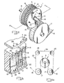
- Figures 1, 2, and 4 illustrate a mandrel apparatus 1 according to one embodiment of the invention comprising an assembly of an insulative disc flange 2, an insulative wheel-shaped mandrel 3, an insulative nozzle plate 4, a conductive titanium anode plate 5, a conductive copper- graphite bushing 6 that is attached to the anode plate 5, an insulative anode extension holder plate 7, an insulative hydraulic distributor plate 8, a shaft 9, an end cap 10 for fitting on the end of the shaft 9, a washer 11 and a sealing ring 12 compressed between the disc flange 2 and the end cap 10.
- the insulative parts 2, 3, 4, 7, and 8 are advantageously machined from a high density polyvinylchloride, and are stacked together with the conductive parts 5 and 6.
- Bolts 13 are assembled through aligned bolt receiving holes 14 through each of the parts 2, 3, 4, 5,7, and 8. These parts are mounted for rotation on the shaft 9.
- a continuous length of strip fed electrical terminals 15 are integral with, and serially spaced along, a carrier strip 16.
- the terminals 15 are shown as electrical receptacles of barrel forms or sleeve forms. These forms are exemplary only, since many forms of electrical receptacles exist.
- the strip fed terminals 15 are shown in Figure 2A as being looped over two idler pulleys 17 and onto a cylindrical alignment surface 18 of the mandrel 3.
- Figure 3 shows a series of radially projecting teeth 19 integral with and projecting from the alignment surface 18.
- the terminals 15 are nested in the spaces that form nests 20 between the teeth 19.
- the carrier strip 16 has pilot holes 21 in which are registered knobs 22 projecting from the mandrel 3.
- the flange 2 provides a rim projecting against and along the carrier strip 16.
- Figure 2A illustrates a belt looped over the pulleys 17 and also over two additional pulleys 25.
- the belt 24 also is held by the pulleys 25 against the terminals 15 that are nested in the nests 20, and the belt retains these terminals 15 against the alignment surface 18 of the mandrel 3.
- the stripped terminals 15 are between the belt 24 and the alignment surface 18, whereas the belt 24 is between the strip feed terminals and the pulleys 17.
- Figure 3 shows a nozzle wheel 4 that is turreted with a plurality of radially spaced orifices or nozzles 26.
- Figures 1 and 4 show that the nozzles 26 are aligned with and open into the nests 20.
- Anode extensions 29 are mounted within the nozzles 26.
- These figures also show the anode plate 5 that includes a plurality of radially spaced anode extension receiving openings 27 that are aligned with and open into the nozzle openings 26.
- the anode extension holder plate 7 includes a plurality of anode extension receiving chambers 28 aligned with and communicating with the openings 27 in the anode plate 5.
- Figure 10 shows an anode extension 29 machined from a conductive metal such as titanium.
- the anode extension has an enlarged diameter body 30 and a reduced diameter elongated probe 31 integral with the body 30.
- a section of the probe 31 is fabricated of a coil spring 31A which makes a probe flexible.
- a radially projecting insulative collar 32 is mounted on the tip of the probe 31.
- One or more flat passageways 33 are recessed in the periphery of the body 30 and extend longitudinally from one end of the body to the other.
- an anode extension body 30 is mounted for reciprocation in each chamber 28.
- the probe 31 of each anode extension body 30 projects into the openings 27, 26 that are aligned with the respective chamber 28.
- the aligned openings 27, 26, together with the chambers 28, cooperate to form anode extension passageways that mount the anode extensions 29 for reciprocation.
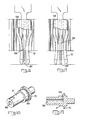
- the probe 31 of each anode extension 29 is mounted for advance into an interior of a terminal 15, as shown in Figure 5, and also for retraction out of an interior of a terminal 15, as shown in Figure 6.
- the body 30 of the anode extension will impinge and stop against the anode plate 5, providing an electrical connection therebetween.
- FIGS. 1 and 4 show that the distributor plate 8 includes a central opening 34 communicating with a plurality of electrolyte passageways 35 that extend radially outward of the opening 34 and communicate with respective anode extension chambers 28.
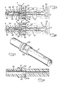
- Figures 7 and 8 show the shaft 9 that is made of conductive stainless steel.
- the shaft 9 is provided with a central stepped cylindrical electrolyte conduit 36 extending entirely the length of the shaft.
- a plurality of electrolyte ports 37 connect the conduit 36 with a channel-shaped electrolyte inlet manifold 38 recessed in the cylindrical periphery of the shaft.
- a plurality of vacuum ports 39 connect the conduit with a channel-shaped vacuum manifold 40 that is recessed in the cylindrical periphery of the shaft 9, so that the central opening 34 of the plate 8 communicates with the manifolds 38, 40.
- the electrolyte passageways 35 that extend to the central opening 34 will communicate with the electrolyte inlet manifold 38, and then the vacuum manifold 40, in turn, as the distributor plate 8 is rotated relative to the shaft 9.
- FIG. 9 taken with Figures 4 and 8, show a vacuum aspirator 41 machined from polyvinylchloride.
- the aspirator 41 is seated in the conduit 36 of the shaft 9.
- One or more longitudinal electrolyte passageways 42 are recessed in the periphery of the aspirator 41 and permit electrolyte flow along the conduit 36 into the ports 37 and the electrolyte inlet manifold 38.
- a longitudinal bore 43 through the aspirator 41 permits additional electrolyte flow through the aspirator 41, to the end of the conduit 36, through a passageway 44 through the end cap 10, and out a conduit 45 that is attached to the end cap 10 and communicates with the cap passageway 44.
- a series of vacuum ports 46 through the aspirator intercept the bore 43.
- the vacuum ports 46 communicate with the vacuum ports 39 and the vacuum manifold 40.
- the electrolyte flow along the bore produces a vacuum in the vacuum ports 46 and also in the vacuum manifold 40. This phenomenon is well known in the art of hydraulic fluid devices.
- FIG 4 shows schematically a plating cell, including a source E of electrical potential applied across the strip 16 and the anode plate 5, a tank 47 containing a plating electrolyte 48 of precious or semi-precious metal ions and a supply hose 49 leading from the tank 47 through a pump 50 and into the conduit 36 of shaft 9.
- a drive sprocket with an axle bushing is secured on the distributor plate 8.
- the sprocket is driven by a chain drive (not shown) to rotate the mandrel apparatus 1 and to feed the strip fed terminals 15 upon the mandrel 3.
- Electrolyte 48 is supplied under pressure from the hose 49 into the conduit 36 of the shaft 9.
- An electrical potential from the source E is applied between the anode plate 5 and the strip fed terminals 15 to produce a current I.
- the terminals 15 serve as a cathode onto which precious or semi-precious metal ions of the electrolyte 48 are to be plated.
- each of the anode extension chambers 28, in turn, will communicate with the electrolyte manifold 38.
- the electrolyte will flow under pressure into the electrolyte manifold 38, and from there into several of the anode extension chambers 28 that communicate with the electrolyte manifold 38.
- the anode extensions 29 in these anode extension chambers 28 will be advanced to positions as shown in Figure 5 by the electrolyte. under pressure.
- Electrolyte will flow past the anode extension bodies 30 along the anode extension passageways 33, and be injected by the nozzles 26 into the interiors of the terminals 15, wetting the terminal interiors and the anode extension probes 31 which are in the terminal interiors. Sufficient ion density and current density are present for the ions to deposit as plating upon the surfaces of the terminal interiors.
- the proximity of the probes 31 to the terminal interiors assures that the surfaces of the terminal interiors are plated, to the exclusion of the other terminal surfaces.
- the collars 32 on the anode extensions are sized nearly to the diameters of the interiors of the terminals to position the anode extension probe precisely along the central axis of the terminal interiors during the plating operation.
- the anode extension chambers 28 will become disconnected from the electrolyte manifold 38, and will become connected with the vacuum manifold 40.
- the vacuum present in the vacuum manifold 40 will tend to draw out residual electrolyte in the several anode extension chambers 28 that communicate with the vacuum manifold 40.
- the vacuum also will retract the anode extensions 29 from their advanced positions, as shown in Figure 5, to their retracted positions, shown in Figure 6. Thereby the probes 31 become withdrawn from the interiors of the terminals 15, plating deposition will cease, and the terminals become removed from the mandrel apparatus 1 as the strip 6 continues to be advanced.
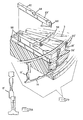
- Figures 13 and 15 illustrate a mandrel apparatus 1' according to an alternative embodiment of the invention comprising an assembly of an insulative bearing case 54, a two-piece insulative disc flange 2', an insulative wheel-shaped mandrel 3', an anode extension-spreader retaining ring 56, and a conductive shaft 9'.
- Bolts 13' are assembled through aligned bolt receiving holes 14' through each of the parts 54, 2', and 3'. These parts are mounted for rotation on the shaft 9'.
- a continuous length of strip fed electrical terminals 15' are integral with, and serially spaced along, a carrier strip 16'.
- the strip fed terminals 15' are strip fed to the apparatus 1' in the same manner as are the strip fed terminals 15 as shown in Figure 2A.
- each anode extension-spreader 29' is comprised of a conductive metal strip 60 and a plastic spreader body 62. The metal strip 60 extends below the plastic spreader.
- the plastic spreader body 62 has a retaining slot 64 along its upper edge which cooperates with the anode extension-spreader retaining ring 56.
- the anode extension-spreader is shaped at its outermost end 66 to spread and fit within the terminals 15' and to properly position the metal anode portion inside the terminal.
- Figure 14 shows that mandrel 3' is turreted with a plurality of radially spaced anode extension-spreader passageways 58 which extend outwardly to the alignment surface 18' and form a series of nests 20' along the periphery mandrel 3'.
- the terminals 15' are held in these nests and against the mandrel as the terminals are plated internally.
- Figure 14 further shows that mandrel 3' is turreted with a plurality of radially spaced orifices or nozzles 26' at the base of the anode extension-spreader passageways 58.
- the metal strips 60 lie within the nozzles 26'.
- the anode extension-spreader 29' is mounted for recriprocation in each passageway 58.
- the shaped end 66 of each anode extension-spreader is mounted for advancing into the slot of a terminal 15' as shown in Figure 16.
- Figure 17 shows the advanced anode extension-spreader in the terminal 15'. As each anode extension-spreader 29' is advanced it is held in contact with the conductive shaft 9', providing an electrical connection therebetween.
- Figures 15, 18 and 19 show the conductive shaft 9' is provided with a central cylindrical electrolyte conduit 36' extending along part of the length of the shaft.
- a channel-shaped electrolyte outlet 68 is recessed in the cylindrical periphery of the shaft 9'. As the mandrel 3' revolves about shaft 9', the nozzles 26' communicate with the electrolyte outlet 68 thus providing access of the electrolyte solution to the terminal 15'.
- Figures 15, 18 and 19 show the asymmetric cam 70 on the shaft 9'.
- the shape of cam 70 can be seen in Figure 20.
- Mandrel 3' has a circular opening 72 at its center which is dimensioned to closely fit and cooperate with shaft 9'.
- the cam 70 fits into a circular opening 72 on the side of mandrel 3' having the anode extension-spreader passageways 58.
- Approximately half of cam 70 fits snugly against passageways 58 while the other part of cam 70 is spaced apart from passageways 58.
- the inner ends 74 of anode extension-spreaders 29' are held snugly against cam 70 by the anode extension-spreader retaining ring 56.
- the anode extension-spreaders 29' are first extended into the terminals 15' as cam 70 moves against passageways 58 and then retracted from terminals 15' where the cam is spaced apart from said passageways.
- Figure 15 shows schematically the mandrel apparatus, including a source E of electrical potential applied across the strip 16 and the conductive shaft 9'.
- a drive sprocket with an axle bushing is secured to the mandrel 3'.
- the sprocket is driven by a chain drive (not shown) to rotate the mandrel apparatus 1' and to feed the strip fed terminals 15' upon the mandrel 3'.
- Electrolyte 48' is supplied under pressure from a plating bath (not shown) into the conduit 36' of the shaft 9'.
- An electrical potential from the source E is applied between the shaft 9' and the strip fed terminals 15' to produce a current I.
- the terminals 15' serve as a cathode onto which precious or semi-precious metal ions of the electrolyte 48' are to be plated.
- each of the nozzles 26' Upon rotation of the mandrel 3', each of the nozzles 26', in turn, will communicate with the electrolyte outlet 68.
- the electrolyte will flow under pressure into the electrolyte outlet 68, and from there into several of the nozzles 26' that communicate with the electrolyte outlet 68.
- the anode extensions 29' in these anode extension-spreader passageways 58 will be advanced to positions as shown in Figure 17 by action of the asymmetric cam 70.
- Electrolyte will flow past the metal portion anode extension-spreader 29' into the interiors of the terminals 15', wetting the terminal interiors and the portion of the anode extensions which are in the terminal interiors. Sufficient ion density and current density are present for the ions to deposit as plating upon the surfaces of the terminal interiors.
- the proximity of the anode extension-spreader end 66 to the terminal interiors assures that the surfaces of the terminal interiors are plated to the exclusion of the other terminal surfaces. Excess electrolyte will flow past the anode extension-spreader and will be returned to the plating bath (not shown).
- the use of mechanical means to reciprocally move the anode extension-spreaders into and out of the terminals eliminates a number of parts that are necessary for the hydraulically operated mechanism to provide reciprocating movement.
- Mechanical means can also be used with mandrel apparatus 1.
- the use of anode extension-spreaders inserted at right angles to the terminals instead of a straight line insertion also reduces the number of parts required for the mandrel apparatus.
- the anode extension-spreaders do become worn after a period of time. Depending upon the type of plastic used, over 25,000 insertions per anode extension-spreader can be made before replacement is necessary.
- the worn anode extension-spreaders are designed to be disposable and are easily replaced by removing bolts 13 and separating the three main pieces. The anode extension-spreader retaining ring is then removed and new anode extension-spreaders inserted.
- Flange 2' is made in two parts to facilitate replacement of the anode extension-spreader retaining ring.
- the present invention relates additionally to an electrical terminal that has an interior with a contact metal deposit applied by the apparatus described in conjunction with Figures 1 through 10 or Figures 13 through 20.
- the deposit has observable characteristics that distinguish from characteristics of plating applied by apparatus and a process other than that described in conjunction with Figures. 1 through 10 or Figures 13 through 20.
- a standard requirement of the electrical industry is that an electrical receptacle of base metal, copper or its alloy, should be plated first with nickel or its alloy, then have its interior plated with a precious or semi-precious metal such as cobalt-gold alloy that assures electrical conductivity. Further, the plating must equal or exceed a specified thickness that allows for wear removal of the layer by abrasion.
- one standard specification requires 0.38 ⁇ m thickness of cobalt-gold plating extending from the end of the receptacle to a depth of 0.51 centimeters within the receptacle interior.
- the exterior surfaces of the receptacle are not subject to wear removal. Therefore, only a flash, i.e., 0.13 11m in thickness, of plating is required.
- noble metal or noble metal alloy may also be comprised of successive layers of noble metals such as gold, palladium, platinum, silver, or their alloys. Successive layers of different noble metals may also be plated on one another, such as an under-layer of palladium followed by an over-layer of gold.
- plating of electrical receptacles was accomplished by the prior processes of plating over a strip of base metal prior to forming the strip into receptacle configurations, or by immersing fully formed electrical receptacles in plating electrolyte and plating all the surfaces of the receptacles.
- Each of these prior processes had disadvantages.
- Forming a base metal strip subsequent to plating applies bending stresses in the plating. Observation by a microscope would reveal stress cracks in the surface of the outer plating layer. The cracks would be most prevalent in the areas of most severe bending. Severe bending also would cause localized separations of the outer plating layer from the metal underlying the outer plating layer. These separations, called occlusions, would be observed by microscopic observation of a cross-section of the outer plating layer and the underlying metal. These stress cracks and occlusions are defects that would permit corrosion of the underlying base metal and would be adverse to quality of the outer plating layer. Further, stamping of the plated base metal produces shears through the plating layers, exposing the base metal underlying the plating.
- Figure 11 depicts a cross-section of an electrical receptacle plated with a layer of nickel 51, and then immersion plated in cobalt-gold electrolyte, using an anode external to the receptacle during plating.
- Both the interior and the exterior of the receptacle receive plating deposit 52.
- the deposit on the interior rapidly tapers in thickness from the end of the receptacle toward the innermost depth of the receptacle. For example, the thickness varies from 0.51 um at the end of the receptacle to zero thickness at a depth of 0.36 centimeters from the end of the receptacle. This tapered characteristic results from the progressive exponential decrease in charge density or current density due to distance from the external anode.
- the deposit Since the exterior of the receptacle is relatively near the external anode, the deposit is thicker than the deposit on the receptacle interior. For example, the deposit has a thickness of 1.1 microns at a depth of 0.05 centimeters and a thickness of 0.51 microns at a depth of 0.36 centimeters. Deposit on the exterior of the receptacle is not subjected to wear removal. Therefore, any plating in excess of a flash, i.e., approximately 0.13 pm in thickness, is wasted consumption.
- Masking i.e., covering, the receptacle exterior during plating will eliminate the exterior deposit.
- masking requires an operation prior to plating and is not conductive to a mass production process. Further, masking does not eliminate wasteful consumption of a tapered deposit on the interior of the receptacle. Upon removal of the masking, an abrupt, not tapered, edge of the plating would be observed where the plating had met the masking.
- the terminal is stamped and formed from a base metal of copper or its alloy.
- a layer of nickel or its alloy is plated over all surfaces of the terminal, including the sheared edges produced during the stamping and forming operations.
- the interior is plated with an outer layer 76 of a precious or semi-precious metal such as gold, platinum, palladium or silver, or the alloys thereof, such as cobalt-gold.
- an outer layer of plating in the form of cobalt-gold of relatively even thickness is deposited along the length extending from the end of the receptacle to a distance of 0.51 centimeters toward the innermost depth of the interior.
- An abrupt and steep taper is at the edges of the plating. There is an absence of cobalt-gold, of equal or greater thickness, on the receptacle exterior.
- the even thickness and abrupt tapered edges are characteristics of the plating deposit achieved by selective plating according to the invention.
- the length of the plating deposit substantially is equal to the length of the anode extension probe 31 that extends within the receptacle interior. At the terminal end of the probe 31, the charge and current densities abruptly cease, causing an abrupt tapered edge of the plating deposit. The charge and current densities also cease at the chamfered end of the receptacle, causing an abrupt tapered edge of the plating deposit.
- the plating deposit does not have the non-tapered edge that would result from masking. Further, the plating deposit is substantially free of stress cracks and occlusions, and has a grain structure characteristic of plating deposit.
- Figure 21 shows a receptacle 15' plated, using the apparatus as described in conjunction with Figures 13 through 20.
- the plating deposit 76' on the interior surface of 15' has the same characteristics as the plating 76 on terminal 15 as shown in Figure 12.
- the receptacles 15 and 15' are only exemplary of the many forms of electrical receptacles, the internal surfaces of which are capable of being plated by the apparatus of the invention.
Landscapes
- Chemical & Material Sciences (AREA)
- Engineering & Computer Science (AREA)
- Chemical Kinetics & Catalysis (AREA)
- Electrochemistry (AREA)
- Materials Engineering (AREA)
- Metallurgy (AREA)
- Organic Chemistry (AREA)
- Crystallography & Structural Chemistry (AREA)
- Manufacturing & Machinery (AREA)
- Electroplating Methods And Accessories (AREA)
Claims (7)
Priority Applications (1)
| Application Number | Priority Date | Filing Date | Title |
|---|---|---|---|
| AT83301271T ATE28905T1 (de) | 1982-03-25 | 1983-03-08 | Kontaktelemente mit plattierten inneren oberflaechen, verfahren und vorrichtung zur selektiven plattierung dieser kontaktelemente. |
Applications Claiming Priority (4)
| Application Number | Priority Date | Filing Date | Title |
|---|---|---|---|
| US06/361,956 US4384926A (en) | 1982-03-25 | 1982-03-25 | Plating interior surfaces of electrical terminals |
| US361956 | 1982-03-25 | ||
| US06/458,005 US4427498A (en) | 1982-03-25 | 1983-01-17 | Selective plating interior surfaces of electrical terminals |
| US458005 | 1983-01-17 |
Publications (2)
| Publication Number | Publication Date |
|---|---|
| EP0091209A1 EP0091209A1 (fr) | 1983-10-12 |
| EP0091209B1 true EP0091209B1 (fr) | 1987-08-12 |
Family
ID=27001499
Family Applications (1)
| Application Number | Title | Priority Date | Filing Date |
|---|---|---|---|
| EP83301271A Expired EP0091209B1 (fr) | 1982-03-25 | 1983-03-08 | Connecteurs électriques portant un revêtement sur la surface interne, appareillage et procédé pour le revêtement sélectif de ces connecteurs |
Country Status (11)
| Country | Link |
|---|---|
| US (1) | US4427498A (fr) |
| EP (1) | EP0091209B1 (fr) |
| AR (1) | AR230536A1 (fr) |
| AU (1) | AU557500B2 (fr) |
| BR (1) | BR8301349A (fr) |
| CA (1) | CA1175520A (fr) |
| DE (1) | DE3372991D1 (fr) |
| ES (2) | ES520960A0 (fr) |
| IE (1) | IE54767B1 (fr) |
| MX (2) | MX153363A (fr) |
| SG (1) | SG63490G (fr) |
Families Citing this family (21)
| Publication number | Priority date | Publication date | Assignee | Title |
|---|---|---|---|---|
| US4473445A (en) * | 1983-12-22 | 1984-09-25 | Amp Incorporated | Selectively plating interior surfaces of loose piece electrical terminals |
| US4555321A (en) * | 1984-06-08 | 1985-11-26 | Amp Incorporated | Selective plating apparatus |
| US4687555A (en) * | 1986-11-10 | 1987-08-18 | Amp Incorporated | Apparatus for selectively plating electrical terminals |
| US4690747A (en) * | 1986-12-23 | 1987-09-01 | Amp Incorporated | Selective plating apparatus |
| US4687562A (en) * | 1986-12-23 | 1987-08-18 | Amp Incorporated | Anode assembly for selectively plating electrical terminals |
| US4859300A (en) * | 1987-07-13 | 1989-08-22 | Enthone, Incorporated | Process for treating plastics with alkaline permanganate solutions |
| US4931150A (en) * | 1988-03-28 | 1990-06-05 | Sifco Industries, Inc. | Selective electroplating apparatus and method of using same |
| US4853099A (en) * | 1988-03-28 | 1989-08-01 | Sifco Industries, Inc. | Selective electroplating apparatus |
| US5002649A (en) * | 1988-03-28 | 1991-03-26 | Sifco Industries, Inc. | Selective stripping apparatus |
| US4904364A (en) * | 1988-11-23 | 1990-02-27 | Amp Incorporated | Anode assembly for selectively plating interior surfaces of electrical terminals |
| US4911813A (en) * | 1988-11-23 | 1990-03-27 | Amp Incorporated | Apparatus for selectively plating interior surfaces of electrical terminals |
| US4900279A (en) * | 1989-04-24 | 1990-02-13 | Die Tech, Inc. | Solder terminal |
| US5292559A (en) * | 1992-01-10 | 1994-03-08 | Amp Incorporated | Laser transfer process |
| FR2688804A1 (fr) * | 1992-03-20 | 1993-09-24 | Souriau & Cie | Procede de depot electrolytique selectif d'un metal notamment d'un metal noble tel que l'or sur la face interne de corps creux en forme de douille notamment d'elements de contact de connecteur machine pour la mise en óoeuvre du procede, produit obtenu. |
| US5725706A (en) * | 1996-03-12 | 1998-03-10 | The Whitaker Corporation | Laser transfer deposition |
| US20070092591A1 (en) * | 2005-10-24 | 2007-04-26 | Cyberonics, Inc. | Vacuum mandrel for use in fabricating an implantable electrode |
| US8551301B2 (en) * | 2008-10-08 | 2013-10-08 | Tyco Electronics Corporation | Electroplating system with electroplating wheel |
| US7842170B1 (en) * | 2009-03-09 | 2010-11-30 | Von Detten Volker | Device for selective plating of electrical contacts for connectors |
| CN109267141A (zh) * | 2018-11-09 | 2019-01-25 | 江苏浩博塑业有限公司 | 一种局部电镀阳极水廊装置 |
| USD1036400S1 (en) * | 2020-11-06 | 2024-07-23 | Hitachi Energy Ltd | Reinforced external turret for electrical equipment |
| USD1032549S1 (en) * | 2020-11-06 | 2024-06-25 | Hitachi Energy Ltd | Reinforced straight turret for electrical equipment |
Family Cites Families (10)
| Publication number | Priority date | Publication date | Assignee | Title |
|---|---|---|---|---|
| US2448117A (en) | 1942-08-05 | 1948-08-31 | Continental Can Co | Electrolytic can treating machine |
| US2503863A (en) | 1943-11-18 | 1950-04-11 | Siegfried G Bart | Apparatus for electroplating the inside of pipes |
| US2477808A (en) | 1946-05-08 | 1949-08-02 | Carl G Jones | Electrolytic apparatus for treatment of moving strip |
| US3137645A (en) * | 1961-10-04 | 1964-06-16 | Philco Corp | Jet electrolytic treating apparatus |
| US3340162A (en) * | 1964-01-27 | 1967-09-05 | Philco Ford Corp | Pitch tolerance compensator for a jetelectrolytic treatment apparatus |
| US3410781A (en) | 1964-11-27 | 1968-11-12 | Ex Cell O Corp | Electrochemical machining apparatus for internal surface deburring |
| US3951761A (en) | 1975-01-31 | 1976-04-20 | Bunker Ramo Corporation | Method and apparatus for electro-plating strip contacts |
| DE2705158C2 (de) * | 1977-02-04 | 1986-02-27 | Schering AG, 1000 Berlin und 4709 Bergkamen | Verfahren zum Teilgalvanisieren |
| US4340449A (en) | 1977-10-11 | 1982-07-20 | Texas Instruments Incorporated | Method for selectively electroplating portions of articles |
| US4384926A (en) | 1982-03-25 | 1983-05-24 | Amp Incorporated | Plating interior surfaces of electrical terminals |
-
1983
- 1983-01-17 US US06/458,005 patent/US4427498A/en not_active Expired - Lifetime
- 1983-02-25 AU AU11877/83A patent/AU557500B2/en not_active Ceased
- 1983-03-08 EP EP83301271A patent/EP0091209B1/fr not_active Expired
- 1983-03-08 DE DE8383301271T patent/DE3372991D1/de not_active Expired
- 1983-03-11 CA CA000423434A patent/CA1175520A/fr not_active Expired
- 1983-03-17 BR BR8301349A patent/BR8301349A/pt not_active IP Right Cessation
- 1983-03-18 AR AR292434A patent/AR230536A1/es active
- 1983-03-22 IE IE618/83A patent/IE54767B1/en not_active IP Right Cessation
- 1983-03-23 MX MX196680A patent/MX153363A/es unknown
- 1983-03-23 MX MX205625A patent/MX156742A/es unknown
- 1983-03-24 ES ES520960A patent/ES520960A0/es active Granted
-
1984
- 1984-04-30 ES ES532076A patent/ES532076A0/es active Granted
-
1990
- 1990-08-01 SG SG634/90A patent/SG63490G/en unknown
Also Published As
| Publication number | Publication date |
|---|---|
| AU557500B2 (en) | 1986-12-24 |
| ES8503037A1 (es) | 1985-02-01 |
| MX153363A (es) | 1986-10-02 |
| AU1187783A (en) | 1983-09-29 |
| IE830618L (en) | 1983-09-25 |
| US4427498A (en) | 1984-01-24 |
| EP0091209A1 (fr) | 1983-10-12 |
| AR230536A1 (es) | 1984-04-30 |
| SG63490G (en) | 1990-12-21 |
| ES532076A0 (es) | 1985-02-01 |
| IE54767B1 (en) | 1990-01-31 |
| DE3372991D1 (en) | 1987-09-17 |
| BR8301349A (pt) | 1983-11-29 |
| MX156742A (es) | 1988-09-28 |
| CA1175520A (fr) | 1984-10-02 |
| ES8407524A1 (es) | 1984-09-16 |
| ES520960A0 (es) | 1984-09-16 |
Similar Documents
| Publication | Publication Date | Title |
|---|---|---|
| US4384926A (en) | Plating interior surfaces of electrical terminals | |
| US4427498A (en) | Selective plating interior surfaces of electrical terminals | |
| EP0148570A2 (fr) | Procédé et appareillage pour le revêtement sélectif de contacts électriques | |
| US4555321A (en) | Selective plating apparatus | |
| EP0241079B1 (fr) | Procédé et appareillage d'électroplacage d'un dépôt métallique sur des composants métalliques et/ou des objets métallisés reliés entre eux | |
| US4294670A (en) | Precision electroplating of metal objects | |
| US4687562A (en) | Anode assembly for selectively plating electrical terminals | |
| CA1188252A (fr) | Contacts femelles a surfaces plaquees, et dispositifs et methode de plaquage desdits contacts | |
| CA1227550A (fr) | Plaquage interne selectif de bornes electriques individuelles | |
| US4543172A (en) | High speed plating apparatus | |
| US4687555A (en) | Apparatus for selectively plating electrical terminals | |
| US9080246B2 (en) | Selective plating apparatus and method | |
| US4904364A (en) | Anode assembly for selectively plating interior surfaces of electrical terminals | |
| US4224117A (en) | Methods of and apparatus for selective plating | |
| EP0847455B1 (fr) | Fabrication de dresseurs au diamant | |
| CN118028929B (zh) | 一种cqfp引线框架表面处理方法及电镀装置 | |
| EP0114216A2 (fr) | Procédé de dépôt électrolytique sélectif | |
| EP0294426B1 (fr) | Appareil de placage selectif ameliore et anode pour cet appareil | |
| KR20200025253A (ko) | 금속판재의 부분 금도금 방법 및 장치 | |
| GB2053967A (en) | Selective plating of pin or socket connectors |
Legal Events
| Date | Code | Title | Description |
|---|---|---|---|
| PUAI | Public reference made under article 153(3) epc to a published international application that has entered the european phase |
Free format text: ORIGINAL CODE: 0009012 |
|
| AK | Designated contracting states |
Designated state(s): AT BE CH DE FR GB IT LI NL SE |
|
| 17P | Request for examination filed |
Effective date: 19840327 |
|
| ITF | It: translation for a ep patent filed | ||
| GRAA | (expected) grant |
Free format text: ORIGINAL CODE: 0009210 |
|
| AK | Designated contracting states |
Kind code of ref document: B1 Designated state(s): AT BE CH DE FR GB IT LI NL SE |
|
| REF | Corresponds to: |
Ref document number: 28905 Country of ref document: AT Date of ref document: 19870815 Kind code of ref document: T |
|
| REF | Corresponds to: |
Ref document number: 3372991 Country of ref document: DE Date of ref document: 19870917 |
|
| ET | Fr: translation filed | ||
| PLBE | No opposition filed within time limit |
Free format text: ORIGINAL CODE: 0009261 |
|
| STAA | Information on the status of an ep patent application or granted ep patent |
Free format text: STATUS: NO OPPOSITION FILED WITHIN TIME LIMIT |
|
| 26N | No opposition filed | ||
| ITTA | It: last paid annual fee | ||
| REG | Reference to a national code |
Ref country code: GB Ref legal event code: 732E |
|
| EAL | Se: european patent in force in sweden |
Ref document number: 83301271.9 |
|
| PGFP | Annual fee paid to national office [announced via postgrant information from national office to epo] |
Ref country code: BE Payment date: 19960409 Year of fee payment: 14 |
|
| PGFP | Annual fee paid to national office [announced via postgrant information from national office to epo] |
Ref country code: SE Payment date: 19970221 Year of fee payment: 15 |
|
| PGFP | Annual fee paid to national office [announced via postgrant information from national office to epo] |
Ref country code: AT Payment date: 19970226 Year of fee payment: 15 |
|
| PG25 | Lapsed in a contracting state [announced via postgrant information from national office to epo] |
Ref country code: BE Effective date: 19970331 |
|
| PGFP | Annual fee paid to national office [announced via postgrant information from national office to epo] |
Ref country code: CH Payment date: 19970423 Year of fee payment: 15 |
|
| BERE | Be: lapsed |
Owner name: AMP INC. (UNE SOC. DE PENNSYLVANIE) Effective date: 19970331 |
|
| PGFP | Annual fee paid to national office [announced via postgrant information from national office to epo] |
Ref country code: NL Payment date: 19971231 Year of fee payment: 16 |
|
| PG25 | Lapsed in a contracting state [announced via postgrant information from national office to epo] |
Ref country code: AT Free format text: LAPSE BECAUSE OF NON-PAYMENT OF DUE FEES Effective date: 19980308 |
|
| PG25 | Lapsed in a contracting state [announced via postgrant information from national office to epo] |
Ref country code: SE Free format text: LAPSE BECAUSE OF NON-PAYMENT OF DUE FEES Effective date: 19980309 |
|
| PG25 | Lapsed in a contracting state [announced via postgrant information from national office to epo] |
Ref country code: LI Free format text: LAPSE BECAUSE OF NON-PAYMENT OF DUE FEES Effective date: 19980331 Ref country code: CH Free format text: LAPSE BECAUSE OF NON-PAYMENT OF DUE FEES Effective date: 19980331 |
|
| REG | Reference to a national code |
Ref country code: CH Ref legal event code: PL |
|
| EUG | Se: european patent has lapsed |
Ref document number: 83301271.9 |
|
| PGFP | Annual fee paid to national office [announced via postgrant information from national office to epo] |
Ref country code: GB Payment date: 19990203 Year of fee payment: 17 |
|
| PGFP | Annual fee paid to national office [announced via postgrant information from national office to epo] |
Ref country code: FR Payment date: 19990302 Year of fee payment: 17 |
|
| PGFP | Annual fee paid to national office [announced via postgrant information from national office to epo] |
Ref country code: DE Payment date: 19990330 Year of fee payment: 17 |
|
| PG25 | Lapsed in a contracting state [announced via postgrant information from national office to epo] |
Ref country code: NL Free format text: LAPSE BECAUSE OF NON-PAYMENT OF DUE FEES Effective date: 19991001 |
|
| NLV4 | Nl: lapsed or anulled due to non-payment of the annual fee |
Effective date: 19991001 |
|
| PG25 | Lapsed in a contracting state [announced via postgrant information from national office to epo] |
Ref country code: GB Free format text: LAPSE BECAUSE OF NON-PAYMENT OF DUE FEES Effective date: 20000308 |
|
| GBPC | Gb: european patent ceased through non-payment of renewal fee |
Effective date: 20000308 |
|
| PG25 | Lapsed in a contracting state [announced via postgrant information from national office to epo] |
Ref country code: FR Free format text: LAPSE BECAUSE OF NON-PAYMENT OF DUE FEES Effective date: 20001130 |
|
| REG | Reference to a national code |
Ref country code: FR Ref legal event code: ST |
|
| PG25 | Lapsed in a contracting state [announced via postgrant information from national office to epo] |
Ref country code: DE Free format text: LAPSE BECAUSE OF NON-PAYMENT OF DUE FEES Effective date: 20010103 |