EP0091267A2 - Rückschleifeinheit für Fernmeldesystem - Google Patents
Rückschleifeinheit für Fernmeldesystem Download PDFInfo
- Publication number
- EP0091267A2 EP0091267A2 EP83301788A EP83301788A EP0091267A2 EP 0091267 A2 EP0091267 A2 EP 0091267A2 EP 83301788 A EP83301788 A EP 83301788A EP 83301788 A EP83301788 A EP 83301788A EP 0091267 A2 EP0091267 A2 EP 0091267A2
- Authority
- EP
- European Patent Office
- Prior art keywords
- winding
- line
- pair
- subscriber
- terminals
- Prior art date
- Legal status (The legal status is an assumption and is not a legal conclusion. Google has not performed a legal analysis and makes no representation as to the accuracy of the status listed.)
- Granted
Links
Images

Classifications
-
- H—ELECTRICITY
- H04—ELECTRIC COMMUNICATION TECHNIQUE
- H04M—TELEPHONIC COMMUNICATION
- H04M3/00—Automatic or semi-automatic exchanges
- H04M3/22—Arrangements for supervision, monitoring or testing
- H04M3/26—Arrangements for supervision, monitoring or testing with means for applying test signals or for measuring
- H04M3/28—Automatic routine testing ; Fault testing; Installation testing; Test methods, test equipment or test arrangements therefor
- H04M3/30—Automatic routine testing ; Fault testing; Installation testing; Test methods, test equipment or test arrangements therefor for subscriber's lines, for the local loop
- H04M3/301—Circuit arrangements at the subscriber's side of the line
Definitions
- This invention relates to telecommunication systems.
- a loop-back facility whereby a subscriber's line can be checked from an exchange or other monitoring location.
- a loop-back unit is provided at the subscriber's end of the line which may be activated by a predetermined signal transmitted along the line from the monitoring location.
- the unit disconnects the subscriber's equipment, and after a suitable delay transmits for a given period a further predetermined signal back down the line to the monitoring location, and then re-connects the subscriber's equipment.
- a loop-back unit for connection at the subscriber's end of a line of a telecommunication system to provide a loop-back facility comprises: a transformer having first, second and third windings, the first and second windings being connected in series in the same sense, between a first pair of terminals for connection to the line and the first winding having a relatively low inductance compared with the second winding; signal detection means connected across the third winding; switching means whereby said second winding may be connected to or disconnected from a second pair of terminals for connection to a subscriber's equipment; and control means responsive to detection of a signal by said detection means to operate the switching means to disconnect the second pair of terminals from the second winding temporarily and apply a predetermined signal to the subscriber's line whilst the subscriber's equipment is so disconnected.
- the relation between the inductances of the first and second windings is such that, in normal operation, in response to a signal applied to said first terminals, the first and second windings produce substantially equal magnetic fluxes in the third winding in operation.
- the first winding preferably comprises two equal sections disposed one on either side of the second winding.
- the unit includes a signal detection transformer 1 having first, second and third windings 3, 5 and 7 wound on a ferromagnetic core 9.
- the first and second windings and a high-valued resistor 11 are connected in series, in the same winding sense, between a pair of terminals 13 of the unit to which are respectively connected the wires of a two-wire line 15 by way of which a subscriber's equipment 17 associated with the unit communicates with the local telephone exchange (not shown).
- the subscriber's equipment 17 is connectable via a pair of terminals 19 across the second winding 5 and the resistor 11 via contacts of a relay switching arrangement 21.
- the switching arrangement 21 is operable to disconnect the winding 5 and resistor 11 from the terminals 19, and hence from the subscriber's equipment 17, and connect them instead to control and signal generator circuits 23.
- the third winding 7 is connected with a tone detection circuit 25 whose output is utilised by the circuits 23, as described below.
- the subscriber's equipment and the exchange line present the same nominal impedance, typically 600 ohms to the unit whilst the windings 3 and 5 have respectively a relatively low and a relatively high inductance.
- the subscriber's equipment 17 is connected across the winding 5 and resistor 11, as shown in Figure 1, the winding 3 presenting a low series impedance and the winding 5 together with resistor 11 presenting a high shunt impedance to signals passing between the subscriber's equipment 17 and the exchange.
- the transformer 1 is virtually 'transparent' to such signals.
- Testing the line 15 is initiated by the transmission down the line 15 from the exchange of an audio tone.
- the resulting currents in the windings 3 and 5 produce substantially equal magnetic fluxes in the transformer core 9 which add together to induce an output signal across the winding 7.
- the circuit 25 detects this signal and produces an output which activates the circuits 23 to operate the switching arrangement 21, thereby to disconnect the subscriber's equipment 17 from the winding 5 and resistor 11 and to connect instead the signal generator in the circuits 23 across the winding 5 and resistor 11.
- the signal generator is then activated to generate an audio tone at a predetermined level for a short period, typically one minute, which tone is transmitted along the line 15 to the exchange where it can be utilised to check the integrity and transmission characteristics of the line 15.
- the circuits 23 re- operate the switching arrangement 21 to re-connect the subscriber's equipment 17 across the winding 5 and resistor 11.
- winding 7 serves to isolate the detection circuit 25 from the line 15 and may be designed to match the tone transmitted from the exchange to the detection circuit.
- the unit will continue to operate satisfactorily even when the subscriber's equipment 17 does not present the correct impedance to the unit, e.g. when the equipment 17 becomes disconnected or presents a short circuit.
- the resistor 11 serves to buffer the winding 5 from the short circuit presented by the subscriber's equipment 17, thus allowing a signal of satisfactorily high level to appear across winding 7. It will be appreciated that in the absence of resistor 11 the short circuited winding 5 would effectively also present a short circuit across the winding 7 with consequent low output across the winding 7. However, in some circumstances, e.g. where the winding 5 is itself of sufficiently high resistance, it may be possible to dispense with resistor 11.
- a further feature of the unit is that signals originating in the subscriber's equipment 17 energise the windings 3 and 5 in such senses that the flux produced in transformer core 9 by winding 5 opposes the flux produced by winding 3 with resulting very small induced voltage across winding 7.
- the inductances of windings 3 and 5 are 300 microhenries and 10 henries respectively, and the core 9 consists of high permeability ferrite material. Where there is a direct voltage on the line 15 the core material must be selected to avoid magnetic saturation.
- the winding 3 is preferably split into two equal sections 3A and 3B with the winding 7 and the associated resistor 11, if present, connected between the two windings 3A and 3B, as shown in Figure 2.
- loop-back unit Whilst the loop-back unit described above by way of example is for use with a two wire exchange line, it will be appreciated that other units in accordance with the invention may be adapted for use with lines having more than two wires, in particular four wires. In the four wire case the unit will normally be adapted to receive a signal from the exchange over one pair of the four wires and transmit a signal to the exchange over the other pair of the four wires.
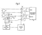
- one pair 27 of wires of the exchange line is connected via a pair of terminals 29, a transformer 31 and two poles A, B of a switching arrangement 33 to a pair of terminals 35 to which the receive input of a subscriber's equipment 37 is connected.
- the transformer has a two part first winding 39A, 39B, a second winding 41 and a third winding 43 connected together and with a resistor 45 and a tone detection circuit 47 in corresponding manner to the transformer shown in Figure 2.
- the send output of the subscriber's equipment 37 is connected to the other pair of wires 49 of the exchange line via terminals 51,two further poles C, D of the switching arrangement 37 and terminals 53.
- the switching arrangement 33 operates under control of a control circuit 55 in response to the output of the tone detection circuit 47.
- the poles of the switching arrangement 33 are in the conditions shown in Figure 3 and the exchange wires 27 and 49 are respectively connected to the receive input and send output of the subscriber's equipment, the transformer 31 being transparent to signals on wires 27 as described above in relation to Figures 1 and 2.
- the transformer 31 similarly supplies an audio tone transmitted on wires 27 to initiate line testing to the detection circuit 47 via winding 43, as described above.
- the control circuit 55 operates switching arrangement 33, thereby to disconnect the subscriber's equipment 37 from both pairs of wires 27 and 49 of the line, and to connect the series connection of the winding 41 and resistor 45 between terminals 53 and hence to wires 49 of the line.
- the audio tone on wires 27 is then transmitted back to the exchange along wires 49 where it can be utilised to check the integrity and transmission characteristics of the line.
- the control circuit 55 re-operates the switching arrangement 33 to re-connect the subscriber's equipment 37 to the line for normal operation. It will be appreciated that in the four wire arrangement the arrangement of transformer 31 enables the loop-back unit to operate satisfactorily despite faults in the subscriber's equipment in the same manner as the transformer in the arrangements of Figures 1 and 2. Moreover, a local tone generator is not required in the loop-back unit to test the line.
Landscapes
- Engineering & Computer Science (AREA)
- Signal Processing (AREA)
- Monitoring And Testing Of Exchanges (AREA)
Applications Claiming Priority (2)
| Application Number | Priority Date | Filing Date | Title |
|---|---|---|---|
| GB8210034 | 1982-04-05 | ||
| GB8210034 | 1982-04-05 |
Publications (3)
| Publication Number | Publication Date |
|---|---|
| EP0091267A2 true EP0091267A2 (de) | 1983-10-12 |
| EP0091267A3 EP0091267A3 (en) | 1984-10-03 |
| EP0091267B1 EP0091267B1 (de) | 1988-01-07 |
Family
ID=10529527
Family Applications (1)
| Application Number | Title | Priority Date | Filing Date |
|---|---|---|---|
| EP83301788A Expired EP0091267B1 (de) | 1982-04-05 | 1983-03-30 | Rückschleifeinheit für Fernmeldesystem |
Country Status (5)
| Country | Link |
|---|---|
| US (1) | US4560842A (de) |
| EP (1) | EP0091267B1 (de) |
| AU (1) | AU556505B2 (de) |
| DE (1) | DE3375269D1 (de) |
| GB (1) | GB2118000B (de) |
Cited By (4)
| Publication number | Priority date | Publication date | Assignee | Title |
|---|---|---|---|---|
| EP0144072A3 (en) * | 1983-11-29 | 1987-08-05 | Fujitsu Limited | Subscriber line radio concentration system |
| EP0168840A3 (en) * | 1984-07-20 | 1988-07-13 | Om Ahuja | Remote actuated switch |
| EP0287369A3 (en) * | 1987-04-14 | 1989-09-13 | Teletech Pty Ltd | Remote disconnection and shortcircuiting apparatus and method |
| GB2368487A (en) * | 2000-10-25 | 2002-05-01 | Alan Robert Perrett | Remote testing system |
Families Citing this family (10)
| Publication number | Priority date | Publication date | Assignee | Title |
|---|---|---|---|---|
| GB2176970B (en) * | 1985-06-20 | 1989-07-19 | Stc Plc | Testing telephone lines |
| US4686696A (en) * | 1985-12-02 | 1987-08-11 | Keptel, Inc. | Transmission line signal sensing circuit employing means for conserving power, especially for use with a telephone disconnect circuit, and associated method |
| US5065424A (en) * | 1987-06-26 | 1991-11-12 | Miller Arthur O | Apparatus for servicing telephones from a remote location |
| US5029204A (en) * | 1989-10-26 | 1991-07-02 | Dsc Communications Corporation | Operational status controller for echo canceling |
| GB2242101B (en) * | 1990-03-15 | 1994-08-31 | Mars Inc | Telephone signalling |
| TW263637B (de) * | 1991-10-04 | 1995-11-21 | At & T Corp | |
| GB9406212D0 (en) * | 1994-03-29 | 1994-05-18 | Plessey Telecomm | Telecommunication customer interface |
| US5644617A (en) * | 1995-01-12 | 1997-07-01 | Teradyne, Inc. | Method and apparatus for testing cables |
| US5848127A (en) * | 1996-04-01 | 1998-12-08 | Hubbell Incorporated | Two-wire channel unit with loopback test capability |
| US6560461B1 (en) | 1997-08-04 | 2003-05-06 | Mundi Fomukong | Authorized location reporting paging system |
Family Cites Families (2)
| Publication number | Priority date | Publication date | Assignee | Title |
|---|---|---|---|---|
| US3843848A (en) * | 1973-01-12 | 1974-10-22 | Magnetic Controls Co | Telephone looptest system |
| US3912882A (en) * | 1973-12-07 | 1975-10-14 | Tm Systems | Remote loop-back terminating unit for testing telephone |
-
1983
- 1983-03-30 DE DE8383301788T patent/DE3375269D1/de not_active Expired
- 1983-03-30 EP EP83301788A patent/EP0091267B1/de not_active Expired
- 1983-03-30 GB GB08308775A patent/GB2118000B/en not_active Expired
- 1983-04-04 US US06/481,843 patent/US4560842A/en not_active Expired - Fee Related
- 1983-04-05 AU AU13158/83A patent/AU556505B2/en not_active Ceased
Cited By (4)
| Publication number | Priority date | Publication date | Assignee | Title |
|---|---|---|---|---|
| EP0144072A3 (en) * | 1983-11-29 | 1987-08-05 | Fujitsu Limited | Subscriber line radio concentration system |
| EP0168840A3 (en) * | 1984-07-20 | 1988-07-13 | Om Ahuja | Remote actuated switch |
| EP0287369A3 (en) * | 1987-04-14 | 1989-09-13 | Teletech Pty Ltd | Remote disconnection and shortcircuiting apparatus and method |
| GB2368487A (en) * | 2000-10-25 | 2002-05-01 | Alan Robert Perrett | Remote testing system |
Also Published As
| Publication number | Publication date |
|---|---|
| US4560842A (en) | 1985-12-24 |
| EP0091267A3 (en) | 1984-10-03 |
| GB2118000A (en) | 1983-10-19 |
| EP0091267B1 (de) | 1988-01-07 |
| AU1315883A (en) | 1983-10-13 |
| AU556505B2 (en) | 1986-11-06 |
| GB8308775D0 (en) | 1983-05-11 |
| GB2118000B (en) | 1985-10-02 |
| DE3375269D1 (en) | 1988-02-11 |
Similar Documents
| Publication | Publication Date | Title |
|---|---|---|
| US4560842A (en) | Telecommunication system loop-back unit | |
| CA1080869A (en) | Electronic hybrid and hybrid repeater | |
| US3636280A (en) | Telephone line testing from remote locations | |
| US3843848A (en) | Telephone looptest system | |
| US5038364A (en) | Transmission line monitoring system | |
| US4549049A (en) | Arrangement for testing a device provided with an echo canceller | |
| US5420886A (en) | Digital transmission equipment | |
| US4551671A (en) | Terminal disconnect and media wire fault detect mechanism | |
| US4079208A (en) | Telecommunications transmission and signalling circuits | |
| US5282237A (en) | Trunk cable fault detection and reconfiguration arrangement in a ring commnications network | |
| US4368362A (en) | Automatic telephone loaded/nonloaded facility type identification circuit | |
| US5345496A (en) | Remote line test facility | |
| US5848127A (en) | Two-wire channel unit with loopback test capability | |
| WO1992017977A1 (en) | Remotely controlled apparatus for conditioning telephone line exclusive of metallic dc bypass pair | |
| US4984262A (en) | Digital service unit | |
| US3875350A (en) | Self-balancing hybrid circuit | |
| US4445007A (en) | Remote testing of subscriber line interface circuits | |
| US2990457A (en) | Tandem echo suppressor circuits | |
| US3749857A (en) | Cable testing device for long-distance cables, particularly for occupied cables | |
| US4284853A (en) | Telecommunication subscriber line access circuit with ground key indication and a device for call signal generation | |
| JPS58501610A (ja) | 通信ラインのための検出回路 | |
| JP2598175Y2 (ja) | インピーダンスボンドの多重系ボンド線脱落検知装置 | |
| US5329414A (en) | Protective relay interface | |
| US2154694A (en) | Communication system | |
| US4686702A (en) | Signal transmission control apparatus |
Legal Events
| Date | Code | Title | Description |
|---|---|---|---|
| PUAI | Public reference made under article 153(3) epc to a published international application that has entered the european phase |
Free format text: ORIGINAL CODE: 0009012 |
|
| AK | Designated contracting states |
Designated state(s): DE FR |
|
| PUAL | Search report despatched |
Free format text: ORIGINAL CODE: 0009013 |
|
| AK | Designated contracting states |
Designated state(s): DE FR |
|
| 17P | Request for examination filed |
Effective date: 19850329 |
|
| 17Q | First examination report despatched |
Effective date: 19860414 |
|
| GRAA | (expected) grant |
Free format text: ORIGINAL CODE: 0009210 |
|
| AK | Designated contracting states |
Kind code of ref document: B1 Designated state(s): DE FR |
|
| REF | Corresponds to: |
Ref document number: 3375269 Country of ref document: DE Date of ref document: 19880211 |
|
| ET | Fr: translation filed | ||
| PLBE | No opposition filed within time limit |
Free format text: ORIGINAL CODE: 0009261 |
|
| STAA | Information on the status of an ep patent application or granted ep patent |
Free format text: STATUS: NO OPPOSITION FILED WITHIN TIME LIMIT |
|
| 26N | No opposition filed | ||
| PGFP | Annual fee paid to national office [announced via postgrant information from national office to epo] |
Ref country code: FR Payment date: 19910227 Year of fee payment: 9 |
|
| PGFP | Annual fee paid to national office [announced via postgrant information from national office to epo] |
Ref country code: DE Payment date: 19910527 Year of fee payment: 9 |
|
| PG25 | Lapsed in a contracting state [announced via postgrant information from national office to epo] |
Ref country code: FR Effective date: 19921130 |
|
| PG25 | Lapsed in a contracting state [announced via postgrant information from national office to epo] |
Ref country code: DE Effective date: 19921201 |
|
| REG | Reference to a national code |
Ref country code: FR Ref legal event code: ST |