EP0091282B1 - Lastfühler, insbesondere zur Zugkraftmessung eines Kraftwagens - Google Patents
Lastfühler, insbesondere zur Zugkraftmessung eines Kraftwagens Download PDFInfo
- Publication number
- EP0091282B1 EP0091282B1 EP83301829A EP83301829A EP0091282B1 EP 0091282 B1 EP0091282 B1 EP 0091282B1 EP 83301829 A EP83301829 A EP 83301829A EP 83301829 A EP83301829 A EP 83301829A EP 0091282 B1 EP0091282 B1 EP 0091282B1
- Authority
- EP
- European Patent Office
- Prior art keywords
- housing
- plunger
- bellows
- transducer
- load sensor
- Prior art date
- Legal status (The legal status is an assumption and is not a legal conclusion. Google has not performed a legal analysis and makes no representation as to the accuracy of the status listed.)
- Expired
Links
Images
Classifications
-
- G—PHYSICS
- G01—MEASURING; TESTING
- G01L—MEASURING FORCE, STRESS, TORQUE, WORK, MECHANICAL POWER, MECHANICAL EFFICIENCY, OR FLUID PRESSURE
- G01L5/00—Apparatus for, or methods of, measuring force, work, mechanical power, or torque, specially adapted for specific purposes
- G01L5/04—Apparatus for, or methods of, measuring force, work, mechanical power, or torque, specially adapted for specific purposes for measuring tension in flexible members, e.g. ropes, cables, wires, threads, belts or bands
- G01L5/10—Apparatus for, or methods of, measuring force, work, mechanical power, or torque, specially adapted for specific purposes for measuring tension in flexible members, e.g. ropes, cables, wires, threads, belts or bands using electrical means
- G01L5/102—Apparatus for, or methods of, measuring force, work, mechanical power, or torque, specially adapted for specific purposes for measuring tension in flexible members, e.g. ropes, cables, wires, threads, belts or bands using electrical means using sensors located at a non-interrupted part of the flexible member
-
- G—PHYSICS
- G01—MEASURING; TESTING
- G01L—MEASURING FORCE, STRESS, TORQUE, WORK, MECHANICAL POWER, MECHANICAL EFFICIENCY, OR FLUID PRESSURE
- G01L1/00—Measuring force or stress, in general
- G01L1/14—Measuring force or stress, in general by measuring variations in capacitance or inductance of electrical elements, e.g. by measuring variations of frequency of electrical oscillators
-
- G—PHYSICS
- G01—MEASURING; TESTING
- G01L—MEASURING FORCE, STRESS, TORQUE, WORK, MECHANICAL POWER, MECHANICAL EFFICIENCY, OR FLUID PRESSURE
- G01L1/00—Measuring force or stress, in general
- G01L1/26—Auxiliary measures taken, or devices used, in connection with the measurement of force, e.g. for preventing influence of transverse components of force, for preventing overload
-
- G—PHYSICS
- G01—MEASURING; TESTING
- G01L—MEASURING FORCE, STRESS, TORQUE, WORK, MECHANICAL POWER, MECHANICAL EFFICIENCY, OR FLUID PRESSURE
- G01L5/00—Apparatus for, or methods of, measuring force, work, mechanical power, or torque, specially adapted for specific purposes
- G01L5/13—Apparatus for, or methods of, measuring force, work, mechanical power, or torque, specially adapted for specific purposes for measuring the tractive or propulsive power of vehicles
- G01L5/136—Force sensors associated with a vehicle traction coupling
Definitions
- the present invention relates to a load sensor comprising an open frame deformable by an applied load, and a transducer attached between two limbs of the frame and providing a signal dependent upon the space between the two limbs.
- Such a sensor may be used in particular as a draft load sensor for a tractor or other vehicle.
- the frame is tensioned by the draft load to pull the said limbs slightly together.
- the transducer measures the distance between the limbs and hence, by virtue of calibration, the draft load.
- the invention relates more specifically to a sensor of the kind set forth in the introductory part of claim 1 and as described in US 4 287 776 (although that sensor is not designed as a draft load sensor).
- US 4 286 776 the housing and plunger are fixed to two frame limbs respectively.
- the object of the present invention is to provide a sensor in which the transducer is in the form of a "snap-in" unit which is easy to remove for servicing or replacement.
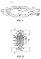
- a draft sensor 10 includes a frame 12 composed of a pair of links 14 and 16 connected together at opposite ends, as described in detail in EP 0 057 100.
- a transducer 20 is inserted in any member where it would be desirable to measure forces, such as in the link or links of a hitch for an agricultural vehicle.
- the links 14 and 16 each have blind bores 22 and 24 drilled therein.
- Support pins 26 and 28 are press-fitted into the bores 22 and 24 and have heads 30 and 32 with rounded bearing surfaces.
- the transducer 20 has a plastics or other non-magnetic cylindrical housing 34 forming a transducer chamber in which is mounted the coil assembly 36 of a conventional linear variable differential transformer (LVDT), such as are available from Schaevitz Engineering or Trans-Tek, Inc. in the USA.
- the housing also forms an annular outer chamber 38 which surrounds the transducer chamber.
- a circuit board 40 may be positioned in the outer chamber 38 for mounting thereon the components of a conventional LVDT circuit, such as described on page 17-56 of Fink's "Electronics Engineers' Handbook", McGraw-Hill, 1975. In this manner, the circuit board 40 is entirely protected from the environment by being located in the outer chamber 38.
- One end of the housing 34 is recessed to provide a socket 42 for engaging the head 32 of the support pin 28.
- the other end of the housing 34 has a bore 44 extending therethrough and communicating with the transducer chamber.
- the transducer 20 also has a non-magnetic plunger 46 with a head 48 having a rounded recess 50 engaging the head 30 of the support pin 26.
- the plunger has a shaft 52 which extends from the head 48 through bore 44 to an end to which is fixed the hollow cylindrical ferrite core member 54 of the LVDT.
- the shaft 52 supports the core 54 for sliding movement within the coil assembly 36.
- a spring 56 is mounted over the shaft 52 and urges the plunger 46 and housing 34 away from each other so that they are maintained in contact with their respective support pins 26 and 28.
- a flexible bellows 58 is sealingly fixed at opposite ends to the plunger 46 and the housing 34 to prevent contamination of the components of the transducer 20 from the environment.
- a silicone rubber material is suitable for the bellows 58.
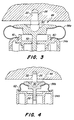
- the bellows 58a and 58b may be formed of stainless steel.
- the bellows 58a and 58b may then perform both the sealing function and the biasing function of the spring 56.
- the spring 56 may be eliminated, as shown in Figs. 3 and 4, unless additional stiffness beyond that provided by the stainless steel bellows 58a and 58b is desired.
- the spring stiffness ensures close fitting against the bearing surfaces on the heads of the pins 26 and 28. However, the force against which the frame is deformed is provided by the strain in the frame itself.
- the bellows 58a has a generally C-shaped cross-section, viewing the left hand of the section, and the housing 34a has an axially extending annular groove 60 which surrounds the bore 44 and which receives an annular collar 61 on one end of the bellows 58a.
- the bellows 58b has a generally S-shaped cross-section, viewing the left-hand half of the section.
- the radially inwardly extending end of the bellows 58b is sealingly coupled to a flange portion of the plunger 52, while the radially outwardly extending end of the bellows 58b is sealingly coupled to the other end of the housing 34b by means of a snap ring 62.
- the transducer 20 may be inserted into or removed from the frame 12 merely by compressing the bellows (the spring if present), to allow the recesses 42 and 50 to be pulled away from their respective support pins 28 and 26.
Landscapes
- Physics & Mathematics (AREA)
- General Physics & Mathematics (AREA)
- Chemical & Material Sciences (AREA)
- Analytical Chemistry (AREA)
- Engineering & Computer Science (AREA)
- Combustion & Propulsion (AREA)
- Force Measurement Appropriate To Specific Purposes (AREA)
- Lifting Devices For Agricultural Implements (AREA)
- Measuring Fluid Pressure (AREA)
- Measurement Of Length, Angles, Or The Like Using Electric Or Magnetic Means (AREA)
- Braking Elements And Transmission Devices (AREA)
- Measurement Of Force In General (AREA)
Claims (8)
Priority Applications (1)
| Application Number | Priority Date | Filing Date | Title |
|---|---|---|---|
| AT83301829T ATE24763T1 (de) | 1982-04-01 | 1983-03-31 | Lastfuehler, insbesondere zur zugkraftmessung eines kraftwagens. |
Applications Claiming Priority (2)
| Application Number | Priority Date | Filing Date | Title |
|---|---|---|---|
| US06/364,372 US4510814A (en) | 1982-04-01 | 1982-04-01 | Snap-in force sensor with bellows |
| US364372 | 1982-04-01 |
Publications (3)
| Publication Number | Publication Date |
|---|---|
| EP0091282A2 EP0091282A2 (de) | 1983-10-12 |
| EP0091282A3 EP0091282A3 (en) | 1984-07-18 |
| EP0091282B1 true EP0091282B1 (de) | 1987-01-07 |
Family
ID=23434229
Family Applications (1)
| Application Number | Title | Priority Date | Filing Date |
|---|---|---|---|
| EP83301829A Expired EP0091282B1 (de) | 1982-04-01 | 1983-03-31 | Lastfühler, insbesondere zur Zugkraftmessung eines Kraftwagens |
Country Status (11)
| Country | Link |
|---|---|
| US (1) | US4510814A (de) |
| EP (1) | EP0091282B1 (de) |
| JP (1) | JPS58189533A (de) |
| AR (1) | AR247631A1 (de) |
| AT (1) | ATE24763T1 (de) |
| AU (1) | AU555852B2 (de) |
| CA (1) | CA1199387A (de) |
| DE (2) | DE3368986D1 (de) |
| ES (1) | ES521143A0 (de) |
| FI (1) | FI831091L (de) |
| ZA (1) | ZA832350B (de) |
Cited By (1)
| Publication number | Priority date | Publication date | Assignee | Title |
|---|---|---|---|---|
| US9003897B2 (en) | 2012-05-10 | 2015-04-14 | Honeywell International Inc. | Temperature compensated force sensor |
Families Citing this family (24)
| Publication number | Priority date | Publication date | Assignee | Title |
|---|---|---|---|---|
| US4422341A (en) * | 1981-12-21 | 1983-12-27 | Deere & Company | Snap-in draft sensor |
| JPH01259228A (ja) * | 1988-04-11 | 1989-10-16 | Fuji Rubber Co Ltd | 圧力センサー |
| DE3908544A1 (de) * | 1989-03-16 | 1990-09-20 | Vdo Schindling | Lastsensor fuer ein kraftfahrzeug |
| BE1004289A3 (fr) * | 1989-07-14 | 1992-10-27 | Humblet Fernand | Cellule de deformation. |
| BE1004290A3 (fr) * | 1989-07-14 | 1992-10-27 | Humblet Fernand | Dispositif de mesure. |
| US5109707A (en) * | 1990-11-13 | 1992-05-05 | Deere & Company | C-beam force sensor |
| US5042586A (en) * | 1990-12-14 | 1991-08-27 | Deere & Company | Tractor draft force sensor |
| AT399484B (de) * | 1993-05-10 | 1995-05-26 | Voest Alpine Eisenbahnsysteme | Einrichtung zur messung der weichenstellkraft |
| US5456122A (en) * | 1994-10-13 | 1995-10-10 | The United States Of America As Represented By The Secretary Of The Navy | Cable load transducer |
| CA2611764C (en) * | 2005-08-19 | 2011-12-06 | Silverbrook Research Pty Ltd | An electronic stylus with a force re-directing coupling |
| US7726197B2 (en) | 2006-04-26 | 2010-06-01 | Honeywell International Inc. | Force sensor package and method of forming same |
| US8327715B2 (en) | 2009-07-02 | 2012-12-11 | Honeywell International Inc. | Force sensor apparatus |
| US8607640B2 (en) * | 2010-07-19 | 2013-12-17 | Odd Harald Steen Eriksen | Sensor for measuring large mechanical strains in shear or lateral translation |
| US8558408B2 (en) | 2010-09-29 | 2013-10-15 | General Electric Company | System and method for providing redundant power to a device |
| US10131419B2 (en) | 2010-10-15 | 2018-11-20 | Goodrich Corporation | Systems and methods for detecting landing gear ground loads |
| US8316725B2 (en) | 2010-12-15 | 2012-11-27 | Honeywell International Inc. | Force sensor |
| US8278779B2 (en) | 2011-02-07 | 2012-10-02 | General Electric Company | System and method for providing redundant power to a device |
| US8496068B1 (en) | 2012-02-01 | 2013-07-30 | Deere & Company | Draft force sensor assembly |
| US9003899B2 (en) | 2012-03-23 | 2015-04-14 | Honeywell International Inc. | Force sensor |
| US8806964B2 (en) | 2012-03-23 | 2014-08-19 | Honeywell International Inc. | Force sensor |
| US9282690B2 (en) | 2013-12-19 | 2016-03-15 | Deere & Company | Three point hitch draft sensing system |
| US9347844B2 (en) * | 2013-12-19 | 2016-05-24 | Deere & Company | Three point hitch draft sensing system |
| DE102016200732B3 (de) * | 2016-01-20 | 2017-06-29 | Schaeffler Technologies AG & Co. KG | Messanordnung zur Kraft- bzw. Drehmomentmessung für ein Maschinenelement und Maschinenelementanordnung mit einer derartigen Messanordnung |
| EP4718047A1 (de) * | 2024-09-30 | 2026-04-01 | Hitachi Energy Ltd | Wägezelle für einen transformator und verfahren zur herstellung einer wägezelle für einen transformator |
Family Cites Families (10)
| Publication number | Priority date | Publication date | Assignee | Title |
|---|---|---|---|---|
| US3022663A (en) * | 1959-08-10 | 1962-02-27 | Performance Measurements Co | Load measuring system |
| US3141327A (en) * | 1962-02-13 | 1964-07-21 | Donald Z Hartranft | Force measuring instruments |
| US3263496A (en) * | 1963-03-14 | 1966-08-02 | Radson Engineering Corp | Load cell and weighing system |
| US3303447A (en) * | 1964-07-13 | 1967-02-07 | W C Dillon & Company Inc | Load cell having a spring biased shaft |
| DE2511413A1 (de) * | 1975-03-15 | 1976-09-23 | Knorr Bremse Gmbh | Elektrischer messfuehler fuer druck, kraft oder weg |
| JPS52146985A (en) * | 1976-06-01 | 1977-12-07 | Roudou Fukushi Jigiyoudan | Device for analysing physically balancing function |
| US4248317A (en) * | 1979-09-10 | 1981-02-03 | Cardinal Scale Manufacturing Company | Load cell apparatus |
| US4253331A (en) * | 1979-09-21 | 1981-03-03 | The Cessna Aircraft Company | Force measuring device |
| US4287776A (en) * | 1979-12-26 | 1981-09-08 | Clarence Johnson | Force transducer |
| US4386533A (en) * | 1981-01-26 | 1983-06-07 | Deere & Company | Capacitance transducer |
-
1982
- 1982-04-01 US US06/364,372 patent/US4510814A/en not_active Expired - Fee Related
-
1983
- 1983-03-11 CA CA000423437A patent/CA1199387A/en not_active Expired
- 1983-03-25 AR AR83292536A patent/AR247631A1/es active
- 1983-03-30 ES ES521143A patent/ES521143A0/es active Granted
- 1983-03-30 AU AU13016/83A patent/AU555852B2/en not_active Ceased
- 1983-03-30 FI FI831091A patent/FI831091L/fi not_active Application Discontinuation
- 1983-03-31 AT AT83301829T patent/ATE24763T1/de not_active IP Right Cessation
- 1983-03-31 DE DE8383301829T patent/DE3368986D1/de not_active Expired
- 1983-03-31 ZA ZA832350A patent/ZA832350B/xx unknown
- 1983-03-31 EP EP83301829A patent/EP0091282B1/de not_active Expired
- 1983-03-31 DE DE198383301829T patent/DE91282T1/de active Pending
- 1983-04-01 JP JP58057748A patent/JPS58189533A/ja active Pending
Cited By (1)
| Publication number | Priority date | Publication date | Assignee | Title |
|---|---|---|---|---|
| US9003897B2 (en) | 2012-05-10 | 2015-04-14 | Honeywell International Inc. | Temperature compensated force sensor |
Also Published As
| Publication number | Publication date |
|---|---|
| CA1199387A (en) | 1986-01-14 |
| AR247631A1 (es) | 1995-01-31 |
| ATE24763T1 (de) | 1987-01-15 |
| EP0091282A2 (de) | 1983-10-12 |
| ZA832350B (en) | 1984-11-28 |
| US4510814A (en) | 1985-04-16 |
| DE3368986D1 (en) | 1987-02-12 |
| FI831091A0 (fi) | 1983-03-30 |
| AU555852B2 (en) | 1986-10-09 |
| EP0091282A3 (en) | 1984-07-18 |
| AU1301683A (en) | 1983-10-06 |
| ES8403616A1 (es) | 1984-03-16 |
| DE91282T1 (de) | 1984-02-16 |
| ES521143A0 (es) | 1984-03-16 |
| FI831091A7 (fi) | 1983-10-02 |
| FI831091L (fi) | 1983-10-02 |
| JPS58189533A (ja) | 1983-11-05 |
Similar Documents
| Publication | Publication Date | Title |
|---|---|---|
| EP0091282A2 (de) | Lastfühler, insbesondere zur Zugkraftmessung eines Kraftwagens | |
| EP3578429B1 (de) | Verbinder für eine elektromechanische bremse | |
| US5094109A (en) | Pressure transmitter with stress isolation depression | |
| EP1686660B1 (de) | Gegenüber der Umgebung abgedichteter selbstzentrierender Verbinder | |
| KR20030025850A (ko) | 차량용 클러치 해제 베어링 | |
| US20060208724A1 (en) | Device for sensing a displacement for a linear drive, and linear drive | |
| KR900016003A (ko) | 차량조향 칼럼용 행정흡수형 중간축 및 그 조립방법 | |
| US20190257708A1 (en) | Fluid pressure sensor | |
| US4744449A (en) | Compact electromagnetic tooth clutch | |
| US4422341A (en) | Snap-in draft sensor | |
| EP0122751B1 (de) | Kugelgelenk | |
| EP0713637A1 (de) | Zugkraftsensorgerät | |
| US20210325266A1 (en) | Force sensor | |
| EP0397392A2 (de) | Konstruktion einer Einschnappassung für eine billige druckempfindliche Maschine | |
| EP1143231A2 (de) | Druckerfassungsapparat | |
| EP0397008B1 (de) | Flexibles Kabel mit Endverbindern | |
| CA1075785A (en) | Electrical feedthrough devices | |
| US4082960A (en) | Pneumatically operated pressure switch, particularly for vehicle tire supervision | |
| KR100813681B1 (ko) | 작용력 센서 | |
| EP0513093A1 (de) | Kapazitiver kraftsensor. | |
| US7150196B2 (en) | Electromagnetic valve and mounting method thereof | |
| JP3975691B2 (ja) | 変位センサ | |
| US6672443B2 (en) | Electromagnetic friction connecting apparatus | |
| CN217275992U (zh) | 行程传感器 | |
| EP0764960A3 (de) | Auf Fluid-Druck ansprechender Schalter und Verfahren zu deren Zusammenbau |
Legal Events
| Date | Code | Title | Description |
|---|---|---|---|
| PUAI | Public reference made under article 153(3) epc to a published international application that has entered the european phase |
Free format text: ORIGINAL CODE: 0009012 |
|
| AK | Designated contracting states |
Designated state(s): AT DE FR GB IT SE |
|
| ITCL | It: translation for ep claims filed |
Representative=s name: LENZI & C. |
|
| EL | Fr: translation of claims filed | ||
| TCAT | At: translation of patent claims filed | ||
| DET | De: translation of patent claims | ||
| PUAL | Search report despatched |
Free format text: ORIGINAL CODE: 0009013 |
|
| AK | Designated contracting states |
Designated state(s): AT DE FR GB IT SE |
|
| 17P | Request for examination filed |
Effective date: 19840808 |
|
| ITF | It: translation for a ep patent filed | ||
| GRAA | (expected) grant |
Free format text: ORIGINAL CODE: 0009210 |
|
| AK | Designated contracting states |
Kind code of ref document: B1 Designated state(s): AT DE FR GB IT SE |
|
| REF | Corresponds to: |
Ref document number: 24763 Country of ref document: AT Date of ref document: 19870115 Kind code of ref document: T |
|
| REF | Corresponds to: |
Ref document number: 3368986 Country of ref document: DE Date of ref document: 19870212 |
|
| PGFP | Annual fee paid to national office [announced via postgrant information from national office to epo] |
Ref country code: AT Payment date: 19870330 Year of fee payment: 5 |
|
| PLBE | No opposition filed within time limit |
Free format text: ORIGINAL CODE: 0009261 |
|
| STAA | Information on the status of an ep patent application or granted ep patent |
Free format text: STATUS: NO OPPOSITION FILED WITHIN TIME LIMIT |
|
| 26N | No opposition filed | ||
| PG25 | Lapsed in a contracting state [announced via postgrant information from national office to epo] |
Ref country code: AT Effective date: 19880331 |
|
| PG25 | Lapsed in a contracting state [announced via postgrant information from national office to epo] |
Ref country code: SE Effective date: 19880401 |
|
| PG25 | Lapsed in a contracting state [announced via postgrant information from national office to epo] |
Ref country code: GB Free format text: LAPSE BECAUSE OF NON-PAYMENT OF DUE FEES Effective date: 19881122 |
|
| GBPC | Gb: european patent ceased through non-payment of renewal fee | ||
| PG25 | Lapsed in a contracting state [announced via postgrant information from national office to epo] |
Ref country code: FR Free format text: LAPSE BECAUSE OF NON-PAYMENT OF DUE FEES Effective date: 19881130 |
|
| PG25 | Lapsed in a contracting state [announced via postgrant information from national office to epo] |
Ref country code: DE Effective date: 19881201 |
|
| REG | Reference to a national code |
Ref country code: FR Ref legal event code: ST |
|
| EUG | Se: european patent has lapsed |
Ref document number: 83301829.4 Effective date: 19890726 |