EP0091289A2 - Moteur de type rotatif ou linéaire actionné avec des moyens de chambre d'échange d'air et des moyens d'avance à l'allumage réglable par des moyens servo-commandés - Google Patents
Moteur de type rotatif ou linéaire actionné avec des moyens de chambre d'échange d'air et des moyens d'avance à l'allumage réglable par des moyens servo-commandés Download PDFInfo
- Publication number
- EP0091289A2 EP0091289A2 EP83301841A EP83301841A EP0091289A2 EP 0091289 A2 EP0091289 A2 EP 0091289A2 EP 83301841 A EP83301841 A EP 83301841A EP 83301841 A EP83301841 A EP 83301841A EP 0091289 A2 EP0091289 A2 EP 0091289A2
- Authority
- EP
- European Patent Office
- Prior art keywords
- cylinder
- cylinders
- explosion
- exhaust
- intake
- Prior art date
- Legal status (The legal status is an assumption and is not a legal conclusion. Google has not performed a legal analysis and makes no representation as to the accuracy of the status listed.)
- Withdrawn
Links
- 238000004880 explosion Methods 0.000 claims abstract description 52
- 230000006835 compression Effects 0.000 claims abstract description 37
- 238000007906 compression Methods 0.000 claims abstract description 37
- 239000000446 fuel Substances 0.000 claims abstract description 36
- 230000033001 locomotion Effects 0.000 claims abstract description 17
- 238000012937 correction Methods 0.000 claims abstract description 11
- 230000000295 complement effect Effects 0.000 claims abstract description 9
- 238000002347 injection Methods 0.000 claims abstract description 4
- 239000007924 injection Substances 0.000 claims abstract description 4
- 238000007789 sealing Methods 0.000 claims abstract description 3
- 238000012545 processing Methods 0.000 claims description 8
- 239000007789 gas Substances 0.000 claims description 7
- 239000000203 mixture Substances 0.000 claims description 7
- 239000002912 waste gas Substances 0.000 claims description 6
- 239000002737 fuel gas Substances 0.000 claims description 5
- 238000005461 lubrication Methods 0.000 claims description 5
- 239000007787 solid Substances 0.000 claims description 5
- 230000005540 biological transmission Effects 0.000 claims description 4
- 238000001816 cooling Methods 0.000 claims description 3
- 239000002283 diesel fuel Substances 0.000 claims description 3
- 239000000956 alloy Substances 0.000 claims description 2
- 229910045601 alloy Inorganic materials 0.000 claims description 2
- 230000008878 coupling Effects 0.000 claims description 2
- 238000010168 coupling process Methods 0.000 claims description 2
- 238000005859 coupling reaction Methods 0.000 claims description 2
- 230000001939 inductive effect Effects 0.000 claims description 2
- 229910052751 metal Inorganic materials 0.000 claims description 2
- 239000002184 metal Substances 0.000 claims description 2
- 239000007921 spray Substances 0.000 claims 1
- 239000003921 oil Substances 0.000 description 6
- 238000010586 diagram Methods 0.000 description 4
- 238000012856 packing Methods 0.000 description 3
- 230000000694 effects Effects 0.000 description 2
- 230000007246 mechanism Effects 0.000 description 2
- 238000000034 method Methods 0.000 description 2
- BASFCYQUMIYNBI-UHFFFAOYSA-N platinum Chemical compound [Pt] BASFCYQUMIYNBI-UHFFFAOYSA-N 0.000 description 2
- 238000002485 combustion reaction Methods 0.000 description 1
- 238000010276 construction Methods 0.000 description 1
- 125000004122 cyclic group Chemical group 0.000 description 1
- 238000013461 design Methods 0.000 description 1
- 239000003502 gasoline Substances 0.000 description 1
- 239000010687 lubricating oil Substances 0.000 description 1
- 229910052697 platinum Inorganic materials 0.000 description 1
Images






Classifications
-
- F—MECHANICAL ENGINEERING; LIGHTING; HEATING; WEAPONS; BLASTING
- F02—COMBUSTION ENGINES; HOT-GAS OR COMBUSTION-PRODUCT ENGINE PLANTS
- F02B—INTERNAL-COMBUSTION PISTON ENGINES; COMBUSTION ENGINES IN GENERAL
- F02B53/00—Internal-combustion aspects of rotary-piston or oscillating-piston engines
- F02B53/12—Ignition
-
- F—MECHANICAL ENGINEERING; LIGHTING; HEATING; WEAPONS; BLASTING
- F01—MACHINES OR ENGINES IN GENERAL; ENGINE PLANTS IN GENERAL; STEAM ENGINES
- F01C—ROTARY-PISTON OR OSCILLATING-PISTON MACHINES OR ENGINES
- F01C11/00—Combinations of two or more machines or engines, each being of rotary-piston or oscillating-piston type
- F01C11/002—Combinations of two or more machines or engines, each being of rotary-piston or oscillating-piston type of similar working principle
- F01C11/004—Combinations of two or more machines or engines, each being of rotary-piston or oscillating-piston type of similar working principle and of complementary function, e.g. internal combustion engine with supercharger
-
- F—MECHANICAL ENGINEERING; LIGHTING; HEATING; WEAPONS; BLASTING
- F02—COMBUSTION ENGINES; HOT-GAS OR COMBUSTION-PRODUCT ENGINE PLANTS
- F02B—INTERNAL-COMBUSTION PISTON ENGINES; COMBUSTION ENGINES IN GENERAL
- F02B53/00—Internal-combustion aspects of rotary-piston or oscillating-piston engines
- F02B53/02—Methods of operating
-
- F—MECHANICAL ENGINEERING; LIGHTING; HEATING; WEAPONS; BLASTING
- F02—COMBUSTION ENGINES; HOT-GAS OR COMBUSTION-PRODUCT ENGINE PLANTS
- F02B—INTERNAL-COMBUSTION PISTON ENGINES; COMBUSTION ENGINES IN GENERAL
- F02B1/00—Engines characterised by fuel-air mixture compression
- F02B1/02—Engines characterised by fuel-air mixture compression with positive ignition
- F02B1/04—Engines characterised by fuel-air mixture compression with positive ignition with fuel-air mixture admission into cylinder
-
- F—MECHANICAL ENGINEERING; LIGHTING; HEATING; WEAPONS; BLASTING
- F02—COMBUSTION ENGINES; HOT-GAS OR COMBUSTION-PRODUCT ENGINE PLANTS
- F02B—INTERNAL-COMBUSTION PISTON ENGINES; COMBUSTION ENGINES IN GENERAL
- F02B75/00—Other engines
- F02B75/02—Engines characterised by their cycles, e.g. six-stroke
- F02B2075/022—Engines characterised by their cycles, e.g. six-stroke having less than six strokes per cycle
- F02B2075/027—Engines characterised by their cycles, e.g. six-stroke having less than six strokes per cycle four
-
- Y—GENERAL TAGGING OF NEW TECHNOLOGICAL DEVELOPMENTS; GENERAL TAGGING OF CROSS-SECTIONAL TECHNOLOGIES SPANNING OVER SEVERAL SECTIONS OF THE IPC; TECHNICAL SUBJECTS COVERED BY FORMER USPC CROSS-REFERENCE ART COLLECTIONS [XRACs] AND DIGESTS
- Y02—TECHNOLOGIES OR APPLICATIONS FOR MITIGATION OR ADAPTATION AGAINST CLIMATE CHANGE
- Y02T—CLIMATE CHANGE MITIGATION TECHNOLOGIES RELATED TO TRANSPORTATION
- Y02T10/00—Road transport of goods or passengers
- Y02T10/10—Internal combustion engine [ICE] based vehicles
- Y02T10/12—Improving ICE efficiencies
Definitions
- This invention relates to a linear or rotary type of engine provided with an air exchanging chamber means, and to an ignition advance means.
- the engine comprises one or more sets of cylinders arranged in a given phase relation, in a plane or arcuate surface which is in contact with a complementary and relatively slidable surface through a lubricating oil film.
- a set of cylinders comprises two rows of cylinders, one row of cylinders arranged in series providing the intake and compression strokes, while the other row of cylinders arranged in series provides the explosion and exhaust strokes.
- Said two rows of cylinders are arranged with the cylinders of one row alternating with the cylinders of the other row.
- the cylinders are not overlapping but each cylinder of one row is connected across to an adjacent cylinder of the other row by means of an air exchanging chamber provided on the complementary sliding surface.
- the intake and compression cylinders and the explosion and exhaust cylinders may be provided in the surface of a part which moves relative to the engine while the air exchanging chambers may be provided in the complementary surface of a part which is fixed relative to the engine or vice versa.
- a corresponding number of retractably sliding valves are provided in said complementary surface each valve being capable of projecting into a corresponding chamber and sealing the part of the chamber on one side of the valve from the part of the chamber on the other side.
- An appropriate ignition spark plug or oil injection nozzle is installed inside each air exchanging chamber, or explosion and exhaust cylinder, to initiate the combustion of fuel and so drive the moving part, i.e.
- a servo-driving ignition advance means that is adjustable by means of a stepper motor or a solenoid may be provided. This is actuated by an analog or digital comparator or a correction output generated by a difference between the sensed value of engine rotation speed and the intake vacuum and a pre-stored best correction value. This is an improvement on the well-known centrifugal block type and the vacuum type of lead-time ignitors which cannot perfectly match the lead-time ignition curve required by the engine.
- This invention provides a linear or rotary type of engine for cyclic operation with separate intake and explosion cylinders connected by an air exchanging chamber.
- this novel engine can generate dynamic output by means of linear type or rotary type drive, the feature of which is that said linear type or rotary type of engine is provided with cylinders formed in a sliding surface.
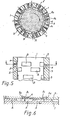
- Figs. 1 and 1-1 a rotary engine in which the sliding surfaces are between moving part (rotor) (1) and fixed part (stator) (2).
- Cylinders (A) for intake and compression and cylinders (B) for explosion and exhaust are connectable by air exchanging chambers (3) provided with spark plugs or injection nozzles (4).
- said engine may be a type, in which either the inner part or the outer part is the rotor (1), and the other part is the stator (2);
- the two parts may both be designed as coaxial cylinders (as shown in Fig. 3) with their adjoining surfaces in close sliding contact.
- An oil film is present between the sliding surfaces to provide lubrication and a hermetic seal.
- one or more than one cylinder sets arranged in a given phase relation are used to perform Otto cycle comprising intake, compression, explosion, and exhaust so as to drive the sliding part (1) either linearly or rotating.
- the cylinder set of said sliding part (1) comprises two rows of cylinder (A) (B), in which one row is the intake and compression cylinders (A), while the other row is the explosion and exhaust cylinders (B) which may be equal or un-equal to the length of the cylinder (A).
- a sectional view of said cylinders (A) (B) is shown in the Figs. 4 and 5 with their phase relation as shown in the plan views of Fig. 4 and 5 in which the cylinders (A) (B) of the two rows are arranged alternately but not overlapped.
- the engines of Figs. 4 and 5 consist of a fixed part (2) and a sliding part (1).
- a number of air exchanging chambers (3) each corresponding to a pair of cylinders (A) (B) in the two sets is provided across said cylinders (A) (B).
- the air exchanging chambers (3) are so arranged as to connect the two cylinders (A) (B) of the pair during the completion of compression stroke prior to the explosion stroke so as to let the compressed and atomized fuel enter the explosion cylinder (cylinder(B)) as shown in Fig. 6.
- the span between every air exchanging chambers (3) is the same as that between the cylinders (A) and (B).
- a spark plug or an oil nozzle (4) is installed in a recess in the fixed part (2).
- a spark plug (4) will be used, while an oil nozzle is used for the diesel engine.
- a movable valve (Al), an intake port (A2), a movable valve (B1), and an exhaust port (B2) are provided opposite to the cylinder (A) and cylinder (B) respectively as shown in Figs.
- Said movable valve (A1) and intake port (A2) are located after the air exchanging chamber (3) in the direction of movement of the moving part (1) and in the line of passage of the cylinder (A) row.
- the movable valve (A1) slides in a slot in fixed part (2) and is provided with a spring (5), by which the outer end of the valve is pressed into close contact with the bottom and the side surface of said cylinder (A).
- the sliding valve (A1) may be aligned at right angles or at a suitable other angle to the sliding part (1). When the sliding part (1) is in motion, air will be sucked into the compression cylinder (A) through intake port (A2).
- the movable valve (Bl) and the exhaust port (B2) are located forward of the air exchange chamber (3) in the direction of movement of the moving part (1) and in the line of passage of the cylinder (B) row.
- the valves (Bl) are sliding valves similar to valves (A1) and are pressed by a spring (5) into close contact with the bottom and side surface of the related explosion and exhaust cylinder (B) at a right angle or other suitable angle.
- the movable valves (A1, B1) when extended into the respective cylinders seal that part of the cylinder on one side of the valve from that part of the cylinder on the other side of the valve. In this way, for example, they block the waste gas in explosion stroke in the cylinder (B) and exhaust it through exhaust port (B2) during the motion of the sliding part (1).
- the cylinder (A) will first receive the movable valve (A1). There is also a movable valve (A1) between two cylinders (A) but that one is restricted into the fixed part (2). As cylinder (A) slides along, the space thereof that has slid over said movable valve (A1) is under low pressure and sucks air and fuel through the intake port (A2). As the cylinder (A) continues moving forwards, the air and fuel in that part of the cylinder (A),on the other side of the movable valve (Al) will be compressed.
- movable valve (Bl) will slide into cylinder (B). Now the air and fuel cylinder (A) will be compressed through the air exchanging chamber (3), into cylinder (B) under high pressure. As the sliding part (1) continuously moves forwards the air exchanging chamber (3) becomes disconnected from the intake and compression cylinder (A), and the spark plug (5) near the cylinder (B) will ignite the air/fuel mixture; the sliding part (1) continues to move forward being driven by means of the arcuate or oblique surface design at the leading end of the cylinder (B). The movable valve (B1) blocks off the waste gas generated during the preceding explosion in cylinder (B) and exhausts it through exhaust port (B2).
- the sets of cylinders may be staggered to provide a more continuous driving force.
- the aforesaid engine may be driven with diesel oil or other fuel by using oil nozzle instead of spark plug (4) and by suitable changing the compression ratio.
- air will be sucked into the compression cylinder (A) via the intake port (A2).
- the air in said cylinder (A) will be compressed into the air exchanging chamber (3)-and the cylinder (B) by means of the movable valve (A1) in next cycle.
- the sliding part (1) has continued to move forwards to separate the air exchanging chamber (3) from the cylinder (A)
- the air in the cylinder (B) has been compressed to a high pressure and temperature.
- oil or other gas fuel is sprayed through a nozzle into the cylinder (B) to be exploded by the high pressure and high temperature and so continuously drive the sliding part (1).
- exhausting of the exhaust gases can be carried out by another method of direct exhausting in next cycle; the structure arrangement for this method is shown in Fig. 8.
- a laterally extending slot (5) is provided at the trailing end of the explosion and exhaust cylinder (B), and at an angle to the direction motion a laterally extending slot (5) is provided.
- an exhaust passage (6) is provided on the corresponding line of motion of the slot (5).
- the engine is connected to said laterally extended slot (5) to exhaust the waste gas.
- the movable valve (Bl) of the engine of this invention may be of one-piece construction, or it may be provided with a spring-loaded head piece (12) of suitable friction resistant metal or alloy for contact with the cylinder walls, as shown in Fig. 13.
- the head of the valve may be enlarged to present an arcuate face to the wall of the cylinder (A) (B) as shown in Fig. 9.
- the line of movement of the valve may be normal to, or inclined to, the line of movement of part (1).
- the movable valve (A1) may be arranged near the air exchanging chamber (3) as shown in Fig. 8 and 9.
- the movable valve (A1) may be installed at the leading side of the air exchanging chamber (3) with respect to. the direction of movement of part (1) and on the compression cylinder (A) so as to have the gas fuel or the compressed air in cylinder (A) completely (100%) compressed into the cylinder (B) of the air exchanging chamber (3) upon movement of the sliding part (1).
- the movable valve (Bl) may be installed near the trailing side of the air exchanging chamber (3).
- the dynamic output of this invention may be transmitted by means of the movable valve (A1) or (B1) pivotally connected to the connecting rod(C), and then by means of the cylinder set (A) (B) arranged in a selected phase relation to generate an Otto cycle for driving a crank (D) to provide conventional dynamic output.
- the outer ring may be a sliding part (1), and the inner ring may be a fixed part (2).
- the dynamic output movable valves (A1) (Bl) may be arranged in a vertical type, a "V"-shaped type, or lateral type to drive the crank (D) through connecting rods (C) as shown in Fig.
- Said inner ring may be a sliding part (1), and said outer ring may be a fixed part (2).
- the cylinder sets (A) (B) may be arranged in a selected phase relation to have the movable valves (A1) (Bl) of each cylinder set in a vertical type arrangement so as to drive one or more sets of cranks (D) in different phase arrangement for a multi-shaft dynamic output as shown in Fig. 14.
- the movable valves (A1) (B1) reciprocatingly sliding inside the fixed part (2) may directly or indirectly drive and control other auxiliary means.
- a sliding packing or head-piece (12) loaded by a spring (13), or other packing piece may be used for keeping said movable valves (A1) (Bl) and the cylinder bottom in close contact with each other during sliding so as to make sure the gas.is being effectively compressed as shown in Fig. 13.
- the servo-driven adjustment advanced ignition means in this invention can reduce this disadvantage of the known centrifugal block and vacuum advance mechanisms by perfectly compensating and matching the linear variation of advancement of ignition in the engine.
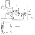
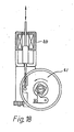
- the structure of said new ignition means is shown in Figs. 16 and 17, in which:
- Fig. 17 the output signals from the sensing means 14 and 15 are fed into a function generator 40 to produce a final output signal to control ignition timing.
- signals (a) and (b) from sensing means 14 and 15 respectively are converted into a final signal represented by the formula where k l , k 2 , and k 3 are constants and f is a function determined by the electrical characteristics of the circuit.
Landscapes
- Engineering & Computer Science (AREA)
- Chemical & Material Sciences (AREA)
- Combustion & Propulsion (AREA)
- Mechanical Engineering (AREA)
- General Engineering & Computer Science (AREA)
- Ignition Installations For Internal Combustion Engines (AREA)
- Output Control And Ontrol Of Special Type Engine (AREA)
Applications Claiming Priority (6)
| Application Number | Priority Date | Filing Date | Title |
|---|---|---|---|
| US36393282A | 1982-03-31 | 1982-03-31 | |
| US363932 | 1982-03-31 | ||
| US39787082A | 1982-07-13 | 1982-07-13 | |
| US397870 | 1982-07-13 | ||
| GB8304849 | 1983-02-22 | ||
| GB838304849A GB8304849D0 (en) | 1983-02-22 | 1983-02-22 | Linear/rotary type of engine |
Related Child Applications (2)
| Application Number | Title | Priority Date | Filing Date |
|---|---|---|---|
| EP86108882.1 Division-Into | 1983-03-31 | ||
| EP86108882A Division EP0208224A3 (fr) | 1982-03-31 | 1983-03-31 | Commande d'allumage pour moteur linéaire ou rotatif |
Publications (2)
| Publication Number | Publication Date |
|---|---|
| EP0091289A2 true EP0091289A2 (fr) | 1983-10-12 |
| EP0091289A3 EP0091289A3 (fr) | 1984-01-18 |
Family
ID=27261987
Family Applications (1)
| Application Number | Title | Priority Date | Filing Date |
|---|---|---|---|
| EP83301841A Withdrawn EP0091289A3 (fr) | 1982-03-31 | 1983-03-31 | Moteur de type rotatif ou linéaire actionné avec des moyens de chambre d'échange d'air et des moyens d'avance à l'allumage réglable par des moyens servo-commandés |
Country Status (1)
| Country | Link |
|---|---|
| EP (1) | EP0091289A3 (fr) |
Cited By (4)
| Publication number | Priority date | Publication date | Assignee | Title |
|---|---|---|---|---|
| EP0172033B1 (fr) * | 1984-08-15 | 1990-10-24 | Tai-Her Yang | Moteur à combustion interne |
| WO1995016850A1 (fr) * | 1993-12-17 | 1995-06-22 | Plextek Limited | Moteur rotatif |
| WO1998038421A1 (fr) | 1997-02-26 | 1998-09-03 | Szelle Von Nagyabony Andor Jan | Machine a piston |
| WO2000034636A1 (fr) * | 1998-11-18 | 2000-06-15 | Mikhailyuk, Valentin Ivanovich | Moteur a combustion interne rotatif |
Families Citing this family (1)
| Publication number | Priority date | Publication date | Assignee | Title |
|---|---|---|---|---|
| RU2163678C1 (ru) * | 1999-08-24 | 2001-02-27 | Всероссийский научно-исследовательский институт минерального сырья им. Н.М. Федоровского | Роторный двигатель внутреннего сгорания |
Family Cites Families (4)
| Publication number | Priority date | Publication date | Assignee | Title |
|---|---|---|---|---|
| DE67997C (de) * | J. PlLECKA in Wsetin, Mähren | Vorrichtung zum Abdichten kreisender Kolben für Wasserspritzen | ||
| CA1006442A (en) * | 1974-01-16 | 1977-03-08 | Tillmann Steckner | Three phase rotary engine |
| US4096846A (en) * | 1974-09-06 | 1978-06-27 | Alfred Biles | Rotary fluid pressure engine |
| DE2847890A1 (de) * | 1978-11-04 | 1980-05-22 | John Allan | Drehkolbenverbrennungsmotor |
-
1983
- 1983-03-31 EP EP83301841A patent/EP0091289A3/fr not_active Withdrawn
Cited By (5)
| Publication number | Priority date | Publication date | Assignee | Title |
|---|---|---|---|---|
| EP0172033B1 (fr) * | 1984-08-15 | 1990-10-24 | Tai-Her Yang | Moteur à combustion interne |
| WO1995016850A1 (fr) * | 1993-12-17 | 1995-06-22 | Plextek Limited | Moteur rotatif |
| US5865152A (en) * | 1993-12-17 | 1999-02-02 | Plextex Limited | Rotary piston internal combustion engine |
| WO1998038421A1 (fr) | 1997-02-26 | 1998-09-03 | Szelle Von Nagyabony Andor Jan | Machine a piston |
| WO2000034636A1 (fr) * | 1998-11-18 | 2000-06-15 | Mikhailyuk, Valentin Ivanovich | Moteur a combustion interne rotatif |
Also Published As
| Publication number | Publication date |
|---|---|
| EP0091289A3 (fr) | 1984-01-18 |
Similar Documents
| Publication | Publication Date | Title |
|---|---|---|
| US4090479A (en) | I.C. engine having improved air or air-fuel induction system | |
| US3957021A (en) | Precombustion chamber rotary piston diesel engine | |
| US4157080A (en) | Internal combustion engine having compartmented combustion chamber | |
| US3246636A (en) | Rotary combustion engine and method of operating same | |
| US5494014A (en) | Rotary internal combustion engine | |
| US4144866A (en) | Internal combustion rotary engine | |
| US3894518A (en) | Stratified charge rotary engine with dual fuel injection | |
| US3809024A (en) | Four-stroke and two-stroke rotary internal combustion engine | |
| US4545346A (en) | Internal combustion heat engine and cycle therefor | |
| US4205528A (en) | Compression ignition controlled free piston-turbine engine | |
| US1239523A (en) | Internal-combustion engine. | |
| US7556014B2 (en) | Reciprocating machines | |
| EP0153325B1 (fr) | Moteur a combustion interne | |
| US3994266A (en) | Rotary diesel engine | |
| US5220893A (en) | Rotary internal combustion engine | |
| EP0091289A2 (fr) | Moteur de type rotatif ou linéaire actionné avec des moyens de chambre d'échange d'air et des moyens d'avance à l'allumage réglable par des moyens servo-commandés | |
| EP0172033B1 (fr) | Moteur à combustion interne | |
| CA1209925A (fr) | Moteur a combustion interne, et cycle de fonctionnement | |
| US3861361A (en) | Rotary engine with piston scavenged precombustion chambers | |
| US4538567A (en) | Internal combustion heat engine | |
| EP0208224A2 (fr) | Commande d'allumage pour moteur linéaire ou rotatif | |
| US4275689A (en) | Internal combustion engine | |
| US4425880A (en) | Rotating cylinder internal combustion engine | |
| US20140190446A1 (en) | Fixed vane rotary abutment engine | |
| US4136647A (en) | Rotary device particularly useful as a rotary engine |
Legal Events
| Date | Code | Title | Description |
|---|---|---|---|
| PUAI | Public reference made under article 153(3) epc to a published international application that has entered the european phase |
Free format text: ORIGINAL CODE: 0009012 |
|
| AK | Designated contracting states |
Designated state(s): AT BE CH DE FR GB IT LI LU NL SE |
|
| PUAL | Search report despatched |
Free format text: ORIGINAL CODE: 0009013 |
|
| AK | Designated contracting states |
Designated state(s): AT BE CH DE FR GB IT LI LU NL SE |
|
| 17P | Request for examination filed |
Effective date: 19840705 |
|
| 17Q | First examination report despatched |
Effective date: 19860228 |
|
| STAA | Information on the status of an ep patent application or granted ep patent |
Free format text: STATUS: THE APPLICATION IS DEEMED TO BE WITHDRAWN |
|
| 18D | Application deemed to be withdrawn |
Effective date: 19860711 |