EP0091361B1 - System zur Befestigung eines länglichen Körpers, etwa eines Sparrens, auf einem tragenden Bauteil - Google Patents
System zur Befestigung eines länglichen Körpers, etwa eines Sparrens, auf einem tragenden Bauteil Download PDFInfo
- Publication number
- EP0091361B1 EP0091361B1 EP83400653A EP83400653A EP0091361B1 EP 0091361 B1 EP0091361 B1 EP 0091361B1 EP 83400653 A EP83400653 A EP 83400653A EP 83400653 A EP83400653 A EP 83400653A EP 0091361 B1 EP0091361 B1 EP 0091361B1
- Authority
- EP
- European Patent Office
- Prior art keywords
- groove
- extension
- branch
- supporting member
- insert
- Prior art date
- Legal status (The legal status is an assumption and is not a legal conclusion. Google has not performed a legal analysis and makes no representation as to the accuracy of the status listed.)
- Expired
Links
- 230000000295 complement effect Effects 0.000 claims description 12
- 230000000149 penetrating effect Effects 0.000 claims description 2
- 230000000284 resting effect Effects 0.000 claims 2
- 238000009434 installation Methods 0.000 description 7
- 238000000034 method Methods 0.000 description 5
- 239000004744 fabric Substances 0.000 description 4
- 238000005553 drilling Methods 0.000 description 3
- 238000004519 manufacturing process Methods 0.000 description 3
- 238000007789 sealing Methods 0.000 description 2
- 230000000712 assembly Effects 0.000 description 1
- 238000000429 assembly Methods 0.000 description 1
- 230000000903 blocking effect Effects 0.000 description 1
- 238000010276 construction Methods 0.000 description 1
- 230000001186 cumulative effect Effects 0.000 description 1
- 238000005520 cutting process Methods 0.000 description 1
- 238000003754 machining Methods 0.000 description 1
- 239000002184 metal Substances 0.000 description 1
- 238000005192 partition Methods 0.000 description 1
- 239000007787 solid Substances 0.000 description 1
- 230000008719 thickening Effects 0.000 description 1
Images



Classifications
-
- E—FIXED CONSTRUCTIONS
- E04—BUILDING
- E04B—GENERAL BUILDING CONSTRUCTIONS; WALLS, e.g. PARTITIONS; ROOFS; FLOORS; CEILINGS; INSULATION OR OTHER PROTECTION OF BUILDINGS
- E04B7/00—Roofs; Roof construction with regard to insulation
- E04B7/02—Roofs; Roof construction with regard to insulation with plane sloping surfaces, e.g. saddle roofs
-
- E—FIXED CONSTRUCTIONS
- E04—BUILDING
- E04D—ROOF COVERINGS; SKY-LIGHTS; GUTTERS; ROOF-WORKING TOOLS
- E04D3/00—Roof covering by making use of flat or curved slabs or stiff sheets
- E04D3/02—Roof covering by making use of flat or curved slabs or stiff sheets of plane slabs, slates, or sheets, or in which the cross-section is unimportant
- E04D3/06—Roof covering by making use of flat or curved slabs or stiff sheets of plane slabs, slates, or sheets, or in which the cross-section is unimportant of glass or other translucent material; Fixing means therefor
-
- E—FIXED CONSTRUCTIONS
- E04—BUILDING
- E04D—ROOF COVERINGS; SKY-LIGHTS; GUTTERS; ROOF-WORKING TOOLS
- E04D3/00—Roof covering by making use of flat or curved slabs or stiff sheets
- E04D3/02—Roof covering by making use of flat or curved slabs or stiff sheets of plane slabs, slates, or sheets, or in which the cross-section is unimportant
- E04D3/06—Roof covering by making use of flat or curved slabs or stiff sheets of plane slabs, slates, or sheets, or in which the cross-section is unimportant of glass or other translucent material; Fixing means therefor
- E04D3/08—Roof covering by making use of flat or curved slabs or stiff sheets of plane slabs, slates, or sheets, or in which the cross-section is unimportant of glass or other translucent material; Fixing means therefor with metal glazing bars
- E04D2003/0806—Roof covering by making use of flat or curved slabs or stiff sheets of plane slabs, slates, or sheets, or in which the cross-section is unimportant of glass or other translucent material; Fixing means therefor with metal glazing bars the supporting section of the glazing bar consisting of one single extruded or rolled metal part
-
- E—FIXED CONSTRUCTIONS
- E04—BUILDING
- E04D—ROOF COVERINGS; SKY-LIGHTS; GUTTERS; ROOF-WORKING TOOLS
- E04D3/00—Roof covering by making use of flat or curved slabs or stiff sheets
- E04D3/02—Roof covering by making use of flat or curved slabs or stiff sheets of plane slabs, slates, or sheets, or in which the cross-section is unimportant
- E04D3/06—Roof covering by making use of flat or curved slabs or stiff sheets of plane slabs, slates, or sheets, or in which the cross-section is unimportant of glass or other translucent material; Fixing means therefor
- E04D3/08—Roof covering by making use of flat or curved slabs or stiff sheets of plane slabs, slates, or sheets, or in which the cross-section is unimportant of glass or other translucent material; Fixing means therefor with metal glazing bars
- E04D2003/0868—Mutual connections and details of glazing bars
- E04D2003/0881—Mutual connections and details of glazing bars on the eaves of the roof
Definitions
- the present invention relates to the field of frames, and in particular metal frames.
- the present invention relates to a system for fixing an elongated part of the chevron type to a support structure, according to a variable and adjustable angle of inclination, of the type according to the preamble of claim 1.
- the amplitude of variation is limited by the shape of the receiving profiles, and it is necessary to use specific profiles, these systems are therefore not universal.
- the present invention now comes to improve the situation by proposing a new standard system which is at the same time simple, fast, safe and solid assembly and which eliminates the disadvantages previously quoted.
- the present invention is particularly well suited for installation on site and allows an almost unlimited variation in the inclination of the rafters.
- the present invention provides a system for fixing a first element forming an elongated chevron-type part, on a second element forming a support structure, comprising in a manner known per se in combination two members forming a support part and mounting bracket, intended to be fixed , in the adjustable position, one on the supporting structure, the other on the elongated part, the support part comprising a generally flat base making it possible to secure the support part on one of the two elements, as well as an extension whose cross section passing through a plane perpendicular to the connection line of the extension on the base is of arcuate shape and arrives substantially perpendicularly on the base and the fixing system being characterized, according to the invention, in that the mounting bracket consists of two branches perpendicular to each other, a first branch being intended to ensure the fixing of the mounting bracket on the other element, tandi s that the second branch is intended to tangent, in the fixing position, the extension of the support piece; said extension and said second branch also have elongated openings carried
- the portion of at least one of the members chosen from the group of the first branch of the mounting bracket or of the base of the support part is of complementary shape with a groove with converging edges provided on the elongated chevron-type part or on the supporting structure and comprises a threaded orifice capable of receiving a pressure screw capable of being brought to bear against the bottom of the groove to immobilize said member in the appropriate position.
- the portion of at least one of the members chosen from the group of the first branch of the mounting bracket or of the base of the support part is intended to come to bear on the exterior of '' a groove with converging edges provided on the elongated chevron-type part or on the support structure and said portion is associated with an insert part whose shape is complementary to said groove, the insert part is intended to be slid into the latter opposite said portion so that by tightening a through screw said portion and coming into engagement in the insert part, it is possible to pinch the converging edges of the groove therebetween, to immobilize said member in an appropriate position.
- the portion of at least one of the members chosen from the group of the first branch of the mounting bracket or of the base of the support piece is intended to come to bear on the outside of a groove with converging edges provided on the elongated chevron-type part or on the support structure, and this portion is associated with an insert part of a shape complementary to said groove and intended to be slid therein in opposite directions; with respect to said portion, the latter and / or the insert being further provided with a projection capable of penetrating between the converging edges of the groove to maintain between said portion and the insert a spacing greater than the thickness of said converging edges, so that by tightening a screw passing through said portion and engaging in the insert part, these can be assembled while allowing translation in the groove.
- the insert part then has at least one threaded orifice capable of receiving a pressure screw capable of being brought to bear against the bottom of the groove to immobilize said insert in an appropriate position.
- the assembly of the chevron-type part on the support structure does not require any drilling or special machining, and therefore saves time compared to previously existing devices.
- the fixing is possible whatever the angle of inclination of the chevron-type part and therefore of the roof; the cooperation of the arched extension of the support piece and the second branch of the mounting bracket also makes it possible to recover manufacturing errors and does not require precise knowledge of the angle of the roof.
- a standard system can therefore be implemented, which allows all types of installation on site.
- the system can easily be made invisible when the installation is finished.
- the system can thus be made invisible, on one side, by the gutter, on the other side, by the supporting structure or crosspiece.
- the elongated opening formed in the second branch of the mounting bracket has the shape of an oblong hole and the elongated opening formed in the extension of the support piece is constituted by a groove of extension generally perpendicular to the connection line of the extension on the base and open opposite this connection line.
- said cross section of the extension of the support piece defines an arc at least equal to a quarter of a circle and the radius of curvature of the extension of the support piece is advantageously determined so that, when the head of the screw which composes the fasteners is positioned on the concave side of the extension, it causes during tightening, a rotation lock of the screw.
- the second branch of the mounting bracket is substantially rectilinear.
- the second branch of the mounting bracket has a generally curved shape complementary to the extension of the support part.
- the support part is fixed to the support structure and the mounting bracket is fixed to the elongated part of the chevron type.
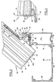
- the fixing system in accordance with the present invention is made up of a combination of two members 10 and 50 respectively forming support piece 10 and mounting bracket 50.
- the support piece 10 is intended to be fixed in an adjustable position on a support structure (80) and the mounting bracket 50 is intended to be fixed in an adjustable position on a piece (90) of chevron type which will be called chevron. in the following description to simplify the presentation, without this expression being limiting.
- the support piece 10 consists of a rectangular base 11 generally flat and of small thickness which is intended to come to bear on the outside of a groove with converging edges provided on the support structure 80 as shown in FIGS. 2 and 3 and as will be described in more detail in the following description, as well as an arcuate extension 13.
- the base 11 has a width greater than the opening of said groove provided on the support structure 80.
- a through hole 12 is formed in the symmetry of the base 11. This through hole 12 is intended to allow the passage of the rod a screw 25 while forming a bearing surface for the head 26 thereof. More specifically, according to the embodiment shown in FIG.
- the head 26 of the screw 25 is frustoconical, therefore, to prevent the head 26 of the screw 25 from protruding above the base 11, the orifice 12 is milled in frustoconical shape complementary to that of the screw and open on the side of the base 11 intended to receive said screw 25.
- the base 11 is also associated with an insert part 20 whose cross section is substantially complementary to the shape of said groove provided on the support structure 80.
- the cross section of the insert 20 and the groove has a shape called dovetail, but many other shapes could be adopted in the context of the invention.
- the insert 20 has on one of its faces a rectilinear rib 22 of a width equal to the opening of the dovetail groove but of a thickness less than the thickness of the converging edges of that -this and two recesses 23 and 24 on either side of this rib 22.
- the rib 22 is intended to penetrate into the opening of the dovetail groove of the support structure while the two recesses 23 and 24 are intended to come to bear against the internal surface of the converging edges of said groove.
- the insert 20 has in its symmetry a threaded through hole 21.
- the support piece 10 can easily be immobilized in an appropriate position on the support structure 80 by pinching the converging edges of the groove between the base 11 of the support piece 10 on the one hand and the piece of insert 20 on the other hand, by tightening the screw 25 in the corresponding tapped hole 21.
- the extension 13 of the support piece 10 is connected to the base 11 along a line referenced 17 arriving substantially perpendicular to the base 11. As shown in FIG. 1, the extension 13 is curved above the base 11. More specifically, the cross section of the extension 11 passing through a plane perpendicular to said connecting line 17, defines an arc of a circle of the order of at least a quarter of a circle, the concavity of which is turned towards the side of the base 11.
- the extension 13 also has, in its symmetry, a groove 16 of extension generally perpendicular to the aforementioned connection line 17 and open opposite the latter.
- the groove 16 thus delimits in the extension two semi-cylindrical sectors 14 and 15.
- the width of the groove 16 is determined so that it allows the passage of the rod 32 of a screw 30, but not point of the head 31 thereof, so that the two semi-cylindrical sectors 14 and 15 play the role of bearing surface for this head 31 of the screw.
- the radius of curvature of the extension 13 of the support piece 10 is determined so that, the head 31 of the screw 30 which composes the fixing members being positioned on the concave side of the extension 13, it causes, during tightening , a blocking in rotation of the screw 30.
- the mounting bracket 50 consists of two branches 51, 55 perpendicular to each other.
- a first branch 51 of rectangular shape is intended to secure the mounting bracket 50 to the rafter 90.
- this first branch preferably has a cross section complementary to a groove with converging edges provided on the rafter 90 , such as a so-called dovetail-shaped groove.
- the first branch also includes, in its symmetry, a threaded orifice 52 passing through the thickness of the branch, capable of receiving a pressure screw 53 capable of being brought to bear against the bottom of the dovetail groove during the tightening in the thread of the tapped hole 52, to immobilize in a suitable position the mounting bracket 50 on the rafter 90 as shown in FIGS. 2 and 3.
- the second branch 55 of the mounting bracket 50 has an elongated rectangular shape and has in its symmetry an oblong hole 56 passing through its thickness.
- the second branch 55 is intended, in the fixing position, to tangent the extension 13 of the support piece 10 in a position such that the oblong hole 56 is opposite the open groove 16 to allow the passage of the rod 32 of the screw 30 on which is intended to be tightened a nut 34 after interposition of a locking washer 33.
- the mounting bracket 50 can be obtained by simple folding of an initially straight piece.
- the second branch has a cross section identical to that of the first branch.
- the aforementioned screws 25 and 53 may advantageously be of the so-called “hexagon socket screw” type, as shown in FIG. 1, without this provision being limiting.
- the second branch 55 of the mounting bracket 50 is substantially rectilinear, it can be provided according to a variant embodiment not shown that the second branch 55 of the mounting bracket 50 has a generally curved shape complementary to the extension of the support piece 10.
- the first branch 51 of the bracket 50 has been extended and provided with a second threaded orifice 52 ', intended again to receive a pressure screw 53.
- the length of the first branch 51 and the position of the second tapped hole 52 ' are determined so that whatever the method of installation, the second tapped hole 52', and therefore the screw 53 engaged therein here, are constantly easily accessible.
- the base 11 is provided on its surface opposite the arcuate extension 13, with a rectilinear rib or projection 18 of width less than the opening separating the converging edges of the groove presented by the support structure.
- this projection 18 and of the aforementioned rib 22 must be greater than the thickness of the converging edges of the groove.
- the support piece 10 can be locked on the insert 20 by means of a screw 26, while allowing the assembly thus formed to slide in the groove .
- the support piece 10 is kept in rotation by the projection 18 which facilitates subsequent adjustment.
- the insert 20 has been elongated relative to the variant embodiment shown in FIG. 1, and two through threaded holes 27 are provided respectively on either side of the above threaded hole 21.
- the orifices 27 are intended to receive pressure screws allowing the insert 20 to be immobilized in a corresponding groove.
- the distance separating these threaded orifices 27 is greater than the width of the base 11 so that these orifices 27 are accessible from either side thereof.
- FIGS. 2 to 4 The supporting structure 80 and the chevron 90 which are shown in FIGS. 2 to 4 will only be described briefly for the proper understanding of the present invention. Of course, these structural parts can take many embodiments.
- the rafters 90 shown in particular in perspective in FIG. 4 are advantageously formed from profiles having, in cross section, a general inverted T shape.
- Said profiled rafters 90 are formed of a central core 91 provided, on either side of two grooves 92 with converging edges in the form of a dovetail, intended to receive seals or gaskets.
- the base 93 of the profiled chevrons 90 transverse to the central core 91, mentioned above, and by which the chevrons 90 are intended to come to rest on the load-bearing structures 80 is also provided with a longitudinal groove 94 with converging edges in the shape of a tail. dovetail open to the outside and intended to receive said first branch 51 of the mounting bracket.
- the upper part of the central core 91 is provided with a thickening 95 which can be used for example for fixing sealing flaps (not shown in the figures).
- the central core 91 of the rafter 90 is advantageously provided with a longitudinal structure 96 having a cross section in the form of a "C". It is thus easy to assemble lateral or finishing sealing parts (referenced 100 in FIGS. 2 and 3), at the end of the rafter 90, using a screw 101 engaged in the orifice 96. Of course this orifice may take any appropriate form.
- the supporting structure 80 shown in FIGS. 2 and 3 in cross section which can for example constitute a veranda or greenhouse crosspiece, consists of two vertical parallel fabrics 81 and 82 connected together and at their ends by two horizontal walls 83 and 84 which are perpendicular thereto, so as to define between these different partitions a chamber 85.
- the upper horizontal wall 83 advantageously has a groove 86 with converging edges of straight section in the form of a dovetail open towards the outside of the chamber 85.
- the vertical canvas 81 has in the vicinity of its upper part a groove 87 with converging edges of cross section in the form of a dovetail also open towards the outside of the chamber 85.
- the two grooves 86 and 87 are intended to receive the insert part 20 associated with the support part 10.
- the lower horizontal wall 84 extends horizontally, from the side of the above-mentioned vertical fabric 81, by a wing 88 which itself has at its end a wing 89 projecting upwards.
- the wings 88 and 89 advantageously form, in cooperation with the fabric 81, a gutter.
- said gutter makes it possible to make invisible on one side the fixing system according to the present invention while the same system is practically made invisible on the other side by the support structure 80.
- the lower horizontal wall 84 also includes a groove 79 with converging edges open towards the outside of the chamber 85, and of cross section in the form of a dovetail.
- the insert 20 in the case of slight slopes, of the order of 0 to 45 °, such as for example in the case of verandas, the insert 20 will preferably be introduced into the groove 87 provided on the vertical fabric 81 while as shown in fig. 3, in in the case of steep slopes of the order of 45 to 90 °, such as for example the case of greenhouses, the insert 20 will preferably be introduced into the groove 86 provided on the upper horizontal wall 83.
- the rafter 90 and the support structure or cross member 80 are crossed, this arrangement makes it possible in particular to support the rafter 90 at any point along its length.
- rafter 90 and the supporting structure in a non-crossed position, but inclined between them, so as to support either the end of a rafter on a cross member, or a rafter on the end of a cross member, using the system shown in fig. 1.
- the base 11 of the support piece 10 must have a width greater than the dimension of the opening of the corresponding groove.
- the purpose of the assembly is to make the second branch 55 of the mounting bracket 50 comprising the oblong hole 56, on the arcuate extension 13 of the support piece 10, by a vertical movement of the chevron 90.
- the latter is "articulated" so that the screw 30 which is preferably previously inserted in the oblong hole 56 and provided with the washer 33 and the nut 34 can be housed in the open groove 16 of the support piece, and that it can be tightened to bind the mounting bracket 50 definitively to the support part 10.
- the insert of the support piece 10, having a tapped hole 21 in its symmetry, must be slid into the groove (86, 87) of the cross section (80).
- the support piece 10 then comes to rest on the insert, so as to make the two holes 12 and 21 correspond.
- the screw 25 must be engaged, and slightly screwed, so as to allow the sliding of the support piece 10, this in order to carry out an adjustment by translation, for the system of FIG. 1, or completely screwed for the system of FIG. 5.
- the support piece 10 When the support piece 10 is appropriately positioned to determine the precise center distance of the rafters 90, the support piece 10 is immobilized, either by tightening the screw 25 (fig. 1) or by tightening the pressure screw in the tapped holes. 27 (fig. 5).
- the mounting bracket 50 comprising a screw 30 provided with its nut 34 (free in the oblong hole 56) is then slid into the groove (94) of the rafter 90.
- the head 31 of the screw 30 is held captive during tightening and can no longer be lifted.
- this circular arc is calculated so as to prevent the “hexagonal head” 31 of the screw 30 from turning when the nut 34 is tightened.
Landscapes
- Engineering & Computer Science (AREA)
- Architecture (AREA)
- Civil Engineering (AREA)
- Structural Engineering (AREA)
- Physics & Mathematics (AREA)
- Electromagnetism (AREA)
- Joining Of Building Structures In Genera (AREA)
- Mutual Connection Of Rods And Tubes (AREA)
Claims (12)
Applications Claiming Priority (2)
| Application Number | Priority Date | Filing Date | Title |
|---|---|---|---|
| FR8205567A FR2524584B1 (fr) | 1982-03-31 | 1982-03-31 | Systeme de fixation d'une piece allongee du type chevron, sur une structure porteuse |
| FR8205567 | 1982-03-31 |
Publications (2)
| Publication Number | Publication Date |
|---|---|
| EP0091361A1 EP0091361A1 (de) | 1983-10-12 |
| EP0091361B1 true EP0091361B1 (de) | 1986-05-14 |
Family
ID=9272614
Family Applications (1)
| Application Number | Title | Priority Date | Filing Date |
|---|---|---|---|
| EP83400653A Expired EP0091361B1 (de) | 1982-03-31 | 1983-03-29 | System zur Befestigung eines länglichen Körpers, etwa eines Sparrens, auf einem tragenden Bauteil |
Country Status (5)
| Country | Link |
|---|---|
| EP (1) | EP0091361B1 (de) |
| DE (1) | DE3363493D1 (de) |
| ES (1) | ES287783Y (de) |
| FR (1) | FR2524584B1 (de) |
| PT (1) | PT76471B (de) |
Cited By (1)
| Publication number | Priority date | Publication date | Assignee | Title |
|---|---|---|---|---|
| USD327214S (en) | 1988-08-30 | 1992-06-23 | El Barador Holding Pty. Ltd. | Bracket for anchoring posts, wall panels or the like |
Families Citing this family (9)
| Publication number | Priority date | Publication date | Assignee | Title |
|---|---|---|---|---|
| GB2259926B (en) * | 1991-09-27 | 1995-04-26 | Scholes Ernest M H | Roofing component |
| EP0612895B1 (de) * | 1993-02-26 | 1997-10-15 | Alain Costa | Schiebedach |
| FR2757891B1 (fr) * | 1996-12-27 | 1999-02-19 | Alcan France | Dispositif d'assemblage de profiles de structure notamment pour toiture de veranda ou analogue |
| GB9906078D0 (en) * | 1999-03-18 | 1999-05-12 | Ultraframe Uk Ltd | Roof construction |
| US6487821B1 (en) * | 1999-04-23 | 2002-12-03 | Vkr Holding A/S | Mounting and hinge fitting for a panel and a panel system comprising such fittings |
| GB2402948B (en) * | 2001-05-26 | 2005-03-30 | Synseal Extrusions Ltd | Method of assembling a building construction |
| DE20212290U1 (de) * | 2002-08-09 | 2003-12-18 | Franz Viegener Ii Gmbh & Co. Kg | Halterung zur Befestigung von Montagegestellen |
| GB2423094A (en) * | 2005-02-09 | 2006-08-16 | Planet Roof Systems Ltd | Connecting rafter to eaves beam |
| CN115522676B (zh) * | 2022-10-25 | 2025-07-25 | 中国五冶集团有限公司 | 圆竹拱屋面及檩条安装方法 |
Family Cites Families (5)
| Publication number | Priority date | Publication date | Assignee | Title |
|---|---|---|---|---|
| GB691488A (en) * | 1950-09-15 | 1953-05-13 | Ici Ltd | Improvements in or relating to methods of fitting curved sheets in building |
| DE1484061A1 (de) * | 1964-09-18 | 1968-12-12 | Ernst Schmidt | Sparrendach |
| JPS5624733Y2 (de) * | 1976-11-02 | 1981-06-11 | ||
| US4261143A (en) * | 1979-07-20 | 1981-04-14 | Michael Rizzo | Pitched roof support structures |
| BE884247A (nl) * | 1980-07-10 | 1981-01-12 | Aluglas P V B A | Dakkonstruktie in aluminium, meer speciaal voor veranda's terrasoverdekkingen, zwembadoverdekkingen en dergelijke |
-
1982
- 1982-03-31 FR FR8205567A patent/FR2524584B1/fr not_active Expired
-
1983
- 1983-03-24 ES ES1983287783U patent/ES287783Y/es not_active Expired
- 1983-03-29 DE DE8383400653T patent/DE3363493D1/de not_active Expired
- 1983-03-29 EP EP83400653A patent/EP0091361B1/de not_active Expired
- 1983-03-29 PT PT76471A patent/PT76471B/pt not_active IP Right Cessation
Cited By (1)
| Publication number | Priority date | Publication date | Assignee | Title |
|---|---|---|---|---|
| USD327214S (en) | 1988-08-30 | 1992-06-23 | El Barador Holding Pty. Ltd. | Bracket for anchoring posts, wall panels or the like |
Also Published As
| Publication number | Publication date |
|---|---|
| PT76471A (fr) | 1983-04-01 |
| FR2524584A1 (fr) | 1983-10-07 |
| FR2524584B1 (fr) | 1985-09-06 |
| EP0091361A1 (de) | 1983-10-12 |
| PT76471B (fr) | 1985-11-18 |
| ES287783U (es) | 1987-08-16 |
| DE3363493D1 (en) | 1986-06-19 |
| ES287783Y (es) | 1988-03-01 |
Similar Documents
| Publication | Publication Date | Title |
|---|---|---|
| EP0091361B1 (de) | System zur Befestigung eines länglichen Körpers, etwa eines Sparrens, auf einem tragenden Bauteil | |
| WO2006123062A2 (fr) | Piece de liaison et ensemble de pieces de liaison orientables | |
| EP0227514B1 (de) | Stützungssystem für Fassadenbekleidungselemente, insbesondere für Kassetten aus gefaltetem Blech | |
| EP0075509B1 (de) | Gelenkige Trägerkonstruktion aus Leichtmetallprofilen | |
| EP0359638B1 (de) | Zusammenstellungssystem für Profile | |
| FR2549933A1 (fr) | Poutre profilee en forme d'i, attaches et assemblages pour de telles poutres | |
| FR3055914A1 (fr) | Dispositif d'entretoisement reglable en longueur | |
| EP0681069B1 (de) | Begehbare, abgehängte Decke | |
| FR2922237A1 (fr) | Attache pour panneaux de faux-plafonds. | |
| EP0143055B1 (de) | Tragekonstruktion zur Bildung eines Ecksparrens für ein Dachgerüst | |
| EP0615072B1 (de) | Verbindungs- und Verriegelungsvorrichtung zwischen einem Profilträger und einem Sparren oder einem ähnlichen Element | |
| EP2163703A1 (de) | Verbindung bzw. Gelenk zwischen zwei Hohlprofilen mit einstellbarem Winkel | |
| FR2951475A1 (fr) | Dispositif de couverture d'un faite de mur | |
| FR3136494A3 (fr) | Système de lambris et raccord | |
| FR2624153A1 (fr) | Structure de support pour constructions annexes, notamment du genre verandas ou analogues | |
| EP3351811A1 (de) | Montagekit für halterungsstrukturen, montageverfahren und halterungsstrukturen, die mithilfe dieses montagekits zusammengebaut wurden | |
| FR2744166A1 (fr) | Piece d'articulation, notamment pour lame orientable d'une fenetre du type jalousie | |
| FR2770867A1 (fr) | Barriere a armature porteuse integree et portail en faisant application | |
| FR2753733A1 (fr) | Dispositif de montage et d'immobilisation d'un poteau de support creux pour cloison interieure d'un local | |
| EP4464903A1 (de) | System zum verbinden zweier metallprofile | |
| FR2930610A1 (fr) | Element de fixation comportant un ecrou pour rail profile ouvert | |
| FR2769931A1 (fr) | Insert de fixation | |
| FR3162234A1 (fr) | Ensemble de structure réglable | |
| FR2889236A1 (fr) | Charniere reglable | |
| FR2682739A1 (fr) | Equerre d'assemblage de deux profiles metalliques. |
Legal Events
| Date | Code | Title | Description |
|---|---|---|---|
| PUAI | Public reference made under article 153(3) epc to a published international application that has entered the european phase |
Free format text: ORIGINAL CODE: 0009012 |
|
| AK | Designated contracting states |
Designated state(s): BE CH DE FR GB IT LI LU NL |
|
| 17P | Request for examination filed |
Effective date: 19840227 |
|
| ITF | It: translation for a ep patent filed | ||
| GRAA | (expected) grant |
Free format text: ORIGINAL CODE: 0009210 |
|
| REG | Reference to a national code |
Ref country code: FR Ref legal event code: TP |
|
| AK | Designated contracting states |
Kind code of ref document: B1 Designated state(s): BE CH DE FR GB IT LI LU NL |
|
| REF | Corresponds to: |
Ref document number: 3363493 Country of ref document: DE Date of ref document: 19860619 |
|
| PLBE | No opposition filed within time limit |
Free format text: ORIGINAL CODE: 0009261 |
|
| STAA | Information on the status of an ep patent application or granted ep patent |
Free format text: STATUS: NO OPPOSITION FILED WITHIN TIME LIMIT |
|
| 26N | No opposition filed | ||
| REG | Reference to a national code |
Ref country code: CH Ref legal event code: PUE Owner name: ALCAN FRANCE |
|
| PGFP | Annual fee paid to national office [announced via postgrant information from national office to epo] |
Ref country code: LU Payment date: 19930217 Year of fee payment: 11 Ref country code: FR Payment date: 19930217 Year of fee payment: 11 |
|
| PGFP | Annual fee paid to national office [announced via postgrant information from national office to epo] |
Ref country code: BE Payment date: 19930218 Year of fee payment: 11 |
|
| ITPR | It: changes in ownership of a european patent |
Owner name: CAMBIO RAGIONE SOCIALE;TECHNAL S.A. |
|
| PGFP | Annual fee paid to national office [announced via postgrant information from national office to epo] |
Ref country code: CH Payment date: 19930317 Year of fee payment: 11 |
|
| PGFP | Annual fee paid to national office [announced via postgrant information from national office to epo] |
Ref country code: GB Payment date: 19930323 Year of fee payment: 11 |
|
| ITTA | It: last paid annual fee | ||
| PGFP | Annual fee paid to national office [announced via postgrant information from national office to epo] |
Ref country code: NL Payment date: 19930331 Year of fee payment: 11 |
|
| EPTA | Lu: last paid annual fee | ||
| PGFP | Annual fee paid to national office [announced via postgrant information from national office to epo] |
Ref country code: DE Payment date: 19930525 Year of fee payment: 11 |
|
| PG25 | Lapsed in a contracting state [announced via postgrant information from national office to epo] |
Ref country code: LU Free format text: LAPSE BECAUSE OF NON-PAYMENT OF DUE FEES Effective date: 19940329 Ref country code: GB Effective date: 19940329 |
|
| PG25 | Lapsed in a contracting state [announced via postgrant information from national office to epo] |
Ref country code: LI Effective date: 19940331 Ref country code: CH Effective date: 19940331 Ref country code: BE Effective date: 19940331 |
|
| BERE | Be: lapsed |
Owner name: ALCAN FRANCE Effective date: 19940331 |
|
| PG25 | Lapsed in a contracting state [announced via postgrant information from national office to epo] |
Ref country code: NL Effective date: 19941001 |
|
| NLV4 | Nl: lapsed or anulled due to non-payment of the annual fee | ||
| GBPC | Gb: european patent ceased through non-payment of renewal fee |
Effective date: 19940329 |
|
| PG25 | Lapsed in a contracting state [announced via postgrant information from national office to epo] |
Ref country code: FR Effective date: 19941130 |
|
| REG | Reference to a national code |
Ref country code: CH Ref legal event code: PL |
|
| PG25 | Lapsed in a contracting state [announced via postgrant information from national office to epo] |
Ref country code: DE Effective date: 19941201 |
|
| BECH | Be: change of holder |
Free format text: 940110 *ALCAN FRANCE |
|
| BECN | Be: change of holder's name |
Effective date: 19940110 |
|
| REG | Reference to a national code |
Ref country code: FR Ref legal event code: ST |