EP0091423B1 - Porte-vent pour un four à cuve - Google Patents
Porte-vent pour un four à cuve Download PDFInfo
- Publication number
- EP0091423B1 EP0091423B1 EP19830890039 EP83890039A EP0091423B1 EP 0091423 B1 EP0091423 B1 EP 0091423B1 EP 19830890039 EP19830890039 EP 19830890039 EP 83890039 A EP83890039 A EP 83890039A EP 0091423 B1 EP0091423 B1 EP 0091423B1
- Authority
- EP
- European Patent Office
- Prior art keywords
- tuyere
- wind
- furnace
- connection according
- tip
- Prior art date
- Legal status (The legal status is an assumption and is not a legal conclusion. Google has not performed a legal analysis and makes no representation as to the accuracy of the status listed.)
- Expired
Links
- 238000002844 melting Methods 0.000 claims description 7
- 239000000919 ceramic Substances 0.000 claims description 6
- 239000004677 Nylon Substances 0.000 claims description 3
- 239000004698 Polyethylene Substances 0.000 claims description 3
- 239000002131 composite material Substances 0.000 claims description 3
- 150000001247 metal acetylides Chemical class 0.000 claims description 3
- 150000002736 metal compounds Chemical class 0.000 claims description 3
- 229910044991 metal oxide Inorganic materials 0.000 claims description 3
- 150000004706 metal oxides Chemical class 0.000 claims description 3
- 150000004767 nitrides Chemical class 0.000 claims description 3
- 229920001778 nylon Polymers 0.000 claims description 3
- 229920001083 polybutene Polymers 0.000 claims description 3
- -1 polyethylene Polymers 0.000 claims description 3
- 229920000573 polyethylene Polymers 0.000 claims description 3
- 229910021332 silicide Inorganic materials 0.000 claims description 3
- 239000000126 substance Substances 0.000 claims description 3
- 238000003825 pressing Methods 0.000 claims description 2
- 230000014759 maintenance of location Effects 0.000 claims 4
- 238000001816 cooling Methods 0.000 description 6
- 229910052751 metal Inorganic materials 0.000 description 5
- 239000002184 metal Substances 0.000 description 5
- 125000006850 spacer group Chemical group 0.000 description 5
- 239000000463 material Substances 0.000 description 4
- 239000000498 cooling water Substances 0.000 description 3
- 230000001590 oxidative effect Effects 0.000 description 3
- 229910001018 Cast iron Inorganic materials 0.000 description 2
- 239000011449 brick Substances 0.000 description 2
- 239000011248 coating agent Substances 0.000 description 2
- 238000000576 coating method Methods 0.000 description 2
- 239000002826 coolant Substances 0.000 description 2
- 150000002739 metals Chemical class 0.000 description 2
- 230000002028 premature Effects 0.000 description 2
- 230000007704 transition Effects 0.000 description 2
- RYGMFSIKBFXOCR-UHFFFAOYSA-N Copper Chemical compound [Cu] RYGMFSIKBFXOCR-UHFFFAOYSA-N 0.000 description 1
- 229910000881 Cu alloy Inorganic materials 0.000 description 1
- 229910016006 MoSi Inorganic materials 0.000 description 1
- ZOKXTWBITQBERF-UHFFFAOYSA-N Molybdenum Chemical compound [Mo] ZOKXTWBITQBERF-UHFFFAOYSA-N 0.000 description 1
- 230000000712 assembly Effects 0.000 description 1
- 238000000429 assembly Methods 0.000 description 1
- 229910052802 copper Inorganic materials 0.000 description 1
- 239000010949 copper Substances 0.000 description 1
- 230000006378 damage Effects 0.000 description 1
- 229910052595 hematite Inorganic materials 0.000 description 1
- 239000011019 hematite Substances 0.000 description 1
- 238000009434 installation Methods 0.000 description 1
- LIKBJVNGSGBSGK-UHFFFAOYSA-N iron(3+);oxygen(2-) Chemical compound [O-2].[O-2].[O-2].[Fe+3].[Fe+3] LIKBJVNGSGBSGK-UHFFFAOYSA-N 0.000 description 1
- 239000001095 magnesium carbonate Substances 0.000 description 1
- ZLNQQNXFFQJAID-UHFFFAOYSA-L magnesium carbonate Chemical compound [Mg+2].[O-]C([O-])=O ZLNQQNXFFQJAID-UHFFFAOYSA-L 0.000 description 1
- 229910000021 magnesium carbonate Inorganic materials 0.000 description 1
- 235000014380 magnesium carbonate Nutrition 0.000 description 1
- 238000004519 manufacturing process Methods 0.000 description 1
- 230000008018 melting Effects 0.000 description 1
- 239000011490 mineral wool Substances 0.000 description 1
- 229910052750 molybdenum Inorganic materials 0.000 description 1
- 239000011733 molybdenum Substances 0.000 description 1
- 229910052758 niobium Inorganic materials 0.000 description 1
- 239000010955 niobium Substances 0.000 description 1
- GUCVJGMIXFAOAE-UHFFFAOYSA-N niobium atom Chemical compound [Nb] GUCVJGMIXFAOAE-UHFFFAOYSA-N 0.000 description 1
- 239000003870 refractory metal Substances 0.000 description 1
- 229910052715 tantalum Inorganic materials 0.000 description 1
- GUVRBAGPIYLISA-UHFFFAOYSA-N tantalum atom Chemical compound [Ta] GUVRBAGPIYLISA-UHFFFAOYSA-N 0.000 description 1
- WFKWXMTUELFFGS-UHFFFAOYSA-N tungsten Chemical compound [W] WFKWXMTUELFFGS-UHFFFAOYSA-N 0.000 description 1
- 229910052721 tungsten Inorganic materials 0.000 description 1
- 239000010937 tungsten Substances 0.000 description 1
- XLYOFNOQVPJJNP-UHFFFAOYSA-N water Substances O XLYOFNOQVPJJNP-UHFFFAOYSA-N 0.000 description 1
Images
Classifications
-
- C—CHEMISTRY; METALLURGY
- C21—METALLURGY OF IRON
- C21B—MANUFACTURE OF IRON OR STEEL
- C21B7/00—Blast furnaces
- C21B7/16—Tuyéres
- C21B7/163—Blowpipe assembly
Definitions
- the invention relates to a nozzle assembly for a shaft furnace, in particular a blast furnace, with a nozzle tip connected to a hot-wind ring line, which leads line-wise into a full-walled uncooled wind mold, preferably made of ceramic sintered mass, with a cavity in the lining for supporting the wind mold and the nozzle tip of the shaft furnace limiting cooled windform box is inserted in the shaft furnace lining.
- a newer nozzle assembly for a blast furnace is known, for example, from Lueger, Lexikon dertechnik, Volume 5, 1963, page 147.
- the hot wind is conducted from a ring line around the blast furnace through the nozzle blocks into the furnace.
- Each nozzle assembly has an uncooled nozzle tip that protrudes into the cavity that is delimited by the water-cooled windshield box (also called the windshield shape).
- the likewise water-cooled wind mold At the tip of the nozzle is the likewise water-cooled wind mold, which projects through the front opening of the wind mold box into the interior, the reaction zone, of the blast furnace.
- the nozzle tip is made of cast hematite. Its tip is also cooled by the water-cooled wind form. The wind form is tightly inserted with an outer cone in an inner cone of the wind form box, and the nozzle tip is pressed against the wind form by means of clamping screws.
- the wind mold is attached to the blast furnace as rigidly as the wind mold box used in the brick lining of the blast furnace.
- the nozzle tip is provided with a refractory lining.
- the water-cooled wind forms are the most heavily loaded fittings in the blast furnace, they are exposed to strong thermal, chemical and mechanical loads and are therefore subject to heavy wear. As a result of these loads, the cooling water circuit breaks again and again, after which it must be switched off. The wind form must then be exchanged, which means an unscheduled shutdown of the furnace.
- double-chamber wind forms are used, as are known for example from DE-OS-2608365. These have two separate cooling circuits, u. between one in a prechamber and one in a main chamber. The antechamber cools the part of the wind form exposed inside the furnace. If the prechamber is damaged, its cooling circuit is pushed off and the wind form can continue to be operated with the main chamber still intact until the blast furnace is scheduled to come to a standstill.
- this solution is not entirely satisfactory because of the heat removal from the hot wind.
- two cooling circuits are very complex.
- a wind form box is indispensable - u. between, on the one hand, because of the high weight of the blast furnace insert consisting of wind mold and wind mold box and, on the other hand, because of the simple replacement of the more or less wearing wind mold while saving an exchange of the wind mold box, which is much less wear-resistant, the task is - according to the invention - a nozzle block with a massive one To provide windform for a blast furnace, but no leakage problems or premature wear occurs at the transition to the windform box, u. between both the wind form and the wind form box.
- the new Dü Senstock can be installed with the wind mold boxes previously used in shaft furnaces, so that an exchange of the wind mold boxes is not necessary when equipping a shaft furnace in operation with nozzle assemblies according to the invention.
- wind form is movably supported relative to the nozzle tip by means of a ball joint and is movable relative to the wind form box by means of a further tight joint connection.
- a compensator is used in the windform box, which is fixed to the windform box by means of a seat ring having a conical surface and which has a holding ring fixing the windform on the end, the compensator expediently having a thin-walled tapering between the seat ring and the holding ring to the windform Has conical shell part.
- tie rods surrounding the cone jacket part are advantageously provided between the seat ring and the retaining ring to absorb forces acting in the axial direction towards the center of the furnace, the tie rods being articulated on the one hand on the retaining ring and on the other hand on the seat ring.
- a ball joint is expediently provided between the compensator and the nozzle tip, the ball joint preferably being formed from an inner conical surface on the compensator and an outer spherical surface on the nozzle tip for easier manufacture.
- the wind mold has a spherical surface at its outer end which is inserted into a conical recess in the nozzle tip which tapers towards the center of the furnace, the nozzle tip expediently at its end facing the furnace center by means of a spherical surface on an inner conical surface of the wind mold box is present.
- a spacer disc which evaporates at the operating temperature of the wind mold for example a disc made of polyethylene, polybutene or nylon, is advantageously used between the outer end of the wind mold and the refractory lining of the nozzle tip, for fixing between the spacer during installation and the fireproof lining of the nozzle tip is provided with a ring nut pressing the spacer against the wind form.
- Highly melting metal oxides and / or metal compounds such as nitrides, silicides, carbides or borides, or metal-ceramic composites (cermets) are advantageous as the material for the uncooled wind form.
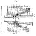
- FIG. 1 showing a section through an axis of a nozzle assembly which is used in a blast furnace according to a first embodiment
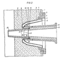
- FIG. 2 an analog representation of a second embodiment.
- a windform ring 3 is welded into the blast furnace shell 1, which is lined on the inside with a refractory lining 2.
- a windform box frame 4 is screwed to this windform ring 3, which has an inner cone 5, into which a windform box 6 with an outer cone 7 is tightly inserted.
- the wind mold box 6 has a cavity 8 through which a coolant (cooling water), which is kept in forced circulation, flows.
- the windform box 6 has an inner cone 10, which serves to receive a compensator 11 made of high-melting metal, which is tightly inserted into this inner cone 10 with a seat ring 12 with a conical surface 13.
- the compensator 11 is uncooled and has a very thin-walled conical jacket part 14, starting from the seat ring 12 and tapering towards the center of the furnace, which merges into a retaining ring 15 for the wind form 16.
- the retaining ring 15 has an inwardly directed flange 17 against which the wind form 16 abuts with a collar 18.
- the wind mold 16 is full-walled and likewise uncooled and is produced from a ceramic sintered mass which is resistant to both oxidizing and reducing conditions. It penetrates the brick lining 2 and protrudes into the furnace interior with a protrusion.
- the nozzle tip 19 which is also uncooled, is provided with a refractory lining 20 and is pressed towards the center of the furnace by means of clamping screws (not shown). It rests with an end spherical surface 21 on the inner surface 22 of the thin-walled conical jacket part 14, u. between where this conical shell part 14 continues in the retaining ring 15 for the wind form 16.
- a ball joint is formed by this inner surface 22 of the conical jacket part 14 and the spherical surface 21, which enables the windform 16 (together with the retaining ring 15) to move with respect to the nozzle tip 19.
- the thin-walled conical jacket part 14 further allows the wind mold 16 to move relative to the wind mold box 6, so that the three parts, wind mold box 6, wind mold 16 and nozzle tip 19, can be moved towards one another and there are no constraints as a result Differences in temperature resulting movements can come.
- tie rods 23 are provided on the circumference of the compensator 11, which are articulated on the one hand on the retaining ring 15 and on the other hand on the seat ring 12 which is inserted in the windform box 6 are.
- a ring nut 24 which is screwed with an external thread into an internal thread of the holding ring 15 and which presses the wind form against the radially inwardly directed flange 17 of the holding ring 15, is used to fix the wind form 16 in the holding ring 15.
- the uncooled wind mold 16 is always installed and removed together with the compensator 11. According to the embodiment shown, the wind mold 16 is designed to be rotationally symmetrical. If you want to direct the hot wind diagonally downwards into the interior of the furnace, a wind mold with an axis inclined with respect to the wind mold box 6 is expediently used.
- the wind form 27 is provided at its rear end with a spherical surface 28 which is inserted into a recess 29 provided at the end of the nozzle tip 25 on the inside of the furnace.
- This recess 29 has an inner conical surface 30 against which the spherical surface 28 of the wind form 27 bears.
- the front opening of the nozzle tip has a slightly larger diameter than the wind form passing through it, so that the wind form can be pivoted relative to the nozzle tip about the center 31 of the spherical surface 28 arranged on the wind form 27.
- the spherical surface 21 of the nozzle tip has the same center point 31 as the spherical surface 28 of the windform 27 in the assembled state of the nozzle assembly.
- the double articulation of the three parts - wind mold box 6, wind mold 27 and nozzle tip 25 - is also given, so that these three parts can be moved independently of one another and can be aligned with one another depending on the temperature-related expansions.
- the end of the nozzle tip on the inside of the furnace which is made of a high-melting metal, has an internal thread into which an annular nut 32 provided with an external thread can be screwed.
- This ring nut clamps the wind form 27 against the nozzle tip 25, but an intermediate layer 33 made of mineral wool and a spacer 34 are provided between the ring nut 32 and the wind form 27.
- This spacer 34 transmits the press-in forces during the assembly of the windform 27 and is made of polyethylene, polybutene or nylon, so that when the nozzle assembly is put into operation it evaporates completely or with less residue left behind. This creates a clearance between the ring nut 32 and the wind form 27, so that the wind form 27 can be properly aligned against the nozzle tip 25.
- the wind form 27 is changed together with the nozzle tip 25, the refractory lining 20 of the nozzle tip 25 being provided only after the wind form 27 has been inserted into the nozzle tip 25 and the ring nut 32 has been tightened.
- the material from which the wind mold 16 or 27 is made must be resistant to oxidizing and reducing conditions.
- High-melting metal oxides and metal compounds (hard materials), such as nitrides, carbides, silicides or borides, as well as coated high-melting metals and metal-ceramic composites (cermets) are suitable for this.
- Refractory metals, such as. B. molybdenum, tungsten, niobium, tantalum can also be used, but they must be protected from an oxidizing atmosphere by means of a coating such as MoSi 2 or WSi 2 , and from an eO / e0 2 atmosphere. Such a coating is a very dense and firmly adhering protection.
- the advantage of the high-melting metals lies in their great mechanical strength.
Landscapes
- Engineering & Computer Science (AREA)
- Chemical & Material Sciences (AREA)
- Manufacturing & Machinery (AREA)
- Materials Engineering (AREA)
- Metallurgy (AREA)
- Organic Chemistry (AREA)
- Furnace Housings, Linings, Walls, And Ceilings (AREA)
- Vertical, Hearth, Or Arc Furnaces (AREA)
Claims (11)
Applications Claiming Priority (2)
| Application Number | Priority Date | Filing Date | Title |
|---|---|---|---|
| AT134382A AT373283B (de) | 1982-04-05 | 1982-04-05 | Duesenstock fuer einen schachtofen |
| AT1343/82 | 1982-04-05 |
Publications (3)
| Publication Number | Publication Date |
|---|---|
| EP0091423A2 EP0091423A2 (fr) | 1983-10-12 |
| EP0091423A3 EP0091423A3 (en) | 1984-07-04 |
| EP0091423B1 true EP0091423B1 (fr) | 1986-05-07 |
Family
ID=3511848
Family Applications (1)
| Application Number | Title | Priority Date | Filing Date |
|---|---|---|---|
| EP19830890039 Expired EP0091423B1 (fr) | 1982-04-05 | 1983-03-17 | Porte-vent pour un four à cuve |
Country Status (3)
| Country | Link |
|---|---|
| EP (1) | EP0091423B1 (fr) |
| AT (1) | AT373283B (fr) |
| DE (1) | DE3363362D1 (fr) |
Cited By (2)
| Publication number | Priority date | Publication date | Assignee | Title |
|---|---|---|---|---|
| DE102010007122A1 (de) * | 2010-02-05 | 2011-08-11 | SAB S.àr.l. | Düsenstock |
| EP4217675A1 (fr) * | 2020-09-28 | 2023-08-02 | Paul Wurth S.A. | Buse refroidie échangeable avec passage d'injecteur en céramique |
Families Citing this family (1)
| Publication number | Priority date | Publication date | Assignee | Title |
|---|---|---|---|---|
| DE4234936C1 (de) * | 1992-10-16 | 1993-10-28 | Gutehoffnungshuette Man | Windformhalterung im Schachtofenpanzer |
Family Cites Families (5)
| Publication number | Priority date | Publication date | Assignee | Title |
|---|---|---|---|---|
| AT7050B (fr) * | 1901-03-01 | 1902-03-10 | Ind De La Magnesite Sa | |
| US1849718A (en) * | 1928-07-05 | 1932-03-15 | Roy H Ledbetter | Blast furnace tuyere |
| DE650859C (de) * | 1934-06-02 | 1937-10-02 | Meutsch | Ausstroemduese, insbesondere Windduese fuer Schachtoefen |
| BE748835A (fr) * | 1970-04-10 | 1970-10-12 | Centre Rech Metallurgique | Perfectionnements aux tuyeres de soufflage, |
| FR2239654B1 (fr) * | 1973-07-30 | 1977-06-17 | Wurth Anciens Ets Paul |
-
1982
- 1982-04-05 AT AT134382A patent/AT373283B/de not_active IP Right Cessation
-
1983
- 1983-03-17 EP EP19830890039 patent/EP0091423B1/fr not_active Expired
- 1983-03-17 DE DE8383890039T patent/DE3363362D1/de not_active Expired
Cited By (2)
| Publication number | Priority date | Publication date | Assignee | Title |
|---|---|---|---|---|
| DE102010007122A1 (de) * | 2010-02-05 | 2011-08-11 | SAB S.àr.l. | Düsenstock |
| EP4217675A1 (fr) * | 2020-09-28 | 2023-08-02 | Paul Wurth S.A. | Buse refroidie échangeable avec passage d'injecteur en céramique |
Also Published As
| Publication number | Publication date |
|---|---|
| ATA134382A (de) | 1983-05-15 |
| EP0091423A2 (fr) | 1983-10-12 |
| EP0091423A3 (en) | 1984-07-04 |
| AT373283B (de) | 1984-01-10 |
| DE3363362D1 (en) | 1986-06-12 |
Similar Documents
| Publication | Publication Date | Title |
|---|---|---|
| DE2459180C3 (de) | Kompensatorverbindung für heiße Medien, insbesondere für Heinwinddüsenstöcke eines Hochofens | |
| DE3019811A1 (de) | Abflussteuerorgan fuer einen schmelzofen | |
| DE2304875C2 (de) | Vorrichtung zum Einblasen von Heisswind in einen Schachtofen, insbesondere Hochofen | |
| EP0942796B1 (fr) | Procede et dispositif pour la division en discontinu de matieres en fusion | |
| EP0302215B1 (fr) | Vanne rotative pour conteneur métallurgique ainsi que rotor et stator pour une telle vanne | |
| EP0091423B1 (fr) | Porte-vent pour un four à cuve | |
| DE3009851A1 (de) | Anlage mit einem reaktorbehaelter, insbesondere zur vergasung fossiler brennstoffe | |
| CH617610A5 (en) | Horizontal continuous casting machine for metals | |
| EP0467254A1 (fr) | Conduite résistant à la chaleur | |
| EP1338360B1 (fr) | Chambre de remplissage pour une machine à couler sous pression | |
| DE3724995A1 (de) | Verfahren zur herstellung eines verbundkoerpers und verbundkoerper selbst | |
| EP0091422B1 (fr) | Porte-vent pour un four à cuve | |
| DE102005038172B4 (de) | Abstichkanal für einen metallurgischen Ofen | |
| EP2516086A1 (fr) | Fermeture coulissante pour un récipient métallurgique | |
| WO1995007956A1 (fr) | Bague d'etancheite glissante pour creer une etancheite entre un tuyau chaud et un boitier | |
| EP0696238B1 (fr) | Systeme permettant de relier une quenouille de coulee de cuve metallurgique a son dispositif de levage, quenouille de coulee appropriee au systeme et procede permettant de realiser ledit systeme | |
| WO2001017712A1 (fr) | Cylindre de laminage | |
| DE102004031242B3 (de) | Elektrodensystem für Glas-Schmelzöfen | |
| DE2825940A1 (de) | Schmiededorn | |
| EP0049239B1 (fr) | Dispositif de coulée en continu | |
| EP0710166B1 (fr) | Systeme permettant de relier une quenouille de cuve metallurgique a son dispositif de levage, quenouille appropriee au systeme et procede de production dudit systeme | |
| DE69900502T2 (de) | Wandaufbau für metallschmelzofen und hochofen mit solchem aufbau | |
| EP1466989A2 (fr) | Plaque de refroidissement | |
| DE3500866C2 (de) | Wechselausguß an einem Schiebeverschluß für den Ausguß an metallurgischen Gefäßen, insbesondere Stahlgießpfannen | |
| DE29515315U1 (de) | Feuerfeste Auskleidung für Gefäße, in denen flüssiges Metall erschmolzen, behandelt, warmgehalten und/oder transportiert wird |
Legal Events
| Date | Code | Title | Description |
|---|---|---|---|
| PUAI | Public reference made under article 153(3) epc to a published international application that has entered the european phase |
Free format text: ORIGINAL CODE: 0009012 |
|
| AK | Designated contracting states |
Designated state(s): BE DE FR GB IT LU NL SE |
|
| PUAL | Search report despatched |
Free format text: ORIGINAL CODE: 0009013 |
|
| AK | Designated contracting states |
Designated state(s): BE DE FR GB IT LU NL SE |
|
| 17P | Request for examination filed |
Effective date: 19841218 |
|
| GRAA | (expected) grant |
Free format text: ORIGINAL CODE: 0009210 |
|
| AK | Designated contracting states |
Kind code of ref document: B1 Designated state(s): BE DE FR GB IT LU NL SE |
|
| REF | Corresponds to: |
Ref document number: 3363362 Country of ref document: DE Date of ref document: 19860612 |
|
| ET | Fr: translation filed | ||
| ITF | It: translation for a ep patent filed | ||
| PLBE | No opposition filed within time limit |
Free format text: ORIGINAL CODE: 0009261 |
|
| STAA | Information on the status of an ep patent application or granted ep patent |
Free format text: STATUS: NO OPPOSITION FILED WITHIN TIME LIMIT |
|
| PG25 | Lapsed in a contracting state [announced via postgrant information from national office to epo] |
Ref country code: LU Free format text: LAPSE BECAUSE OF NON-PAYMENT OF DUE FEES Effective date: 19870331 |
|
| PGFP | Annual fee paid to national office [announced via postgrant information from national office to epo] |
Ref country code: NL Payment date: 19870331 Year of fee payment: 5 |
|
| 26N | No opposition filed | ||
| PG25 | Lapsed in a contracting state [announced via postgrant information from national office to epo] |
Ref country code: SE Effective date: 19880318 |
|
| BERE | Be: lapsed |
Owner name: VOEST-ALPINE A.G. Effective date: 19880331 |
|
| PG25 | Lapsed in a contracting state [announced via postgrant information from national office to epo] |
Ref country code: NL Effective date: 19881001 |
|
| NLV4 | Nl: lapsed or anulled due to non-payment of the annual fee | ||
| PG25 | Lapsed in a contracting state [announced via postgrant information from national office to epo] |
Ref country code: GB Free format text: LAPSE BECAUSE OF NON-PAYMENT OF DUE FEES Effective date: 19881122 |
|
| GBPC | Gb: european patent ceased through non-payment of renewal fee | ||
| PG25 | Lapsed in a contracting state [announced via postgrant information from national office to epo] |
Ref country code: FR Free format text: LAPSE BECAUSE OF NON-PAYMENT OF DUE FEES Effective date: 19881130 |
|
| PG25 | Lapsed in a contracting state [announced via postgrant information from national office to epo] |
Ref country code: DE Effective date: 19881201 |
|
| REG | Reference to a national code |
Ref country code: FR Ref legal event code: ST |
|
| PG25 | Lapsed in a contracting state [announced via postgrant information from national office to epo] |
Ref country code: BE Effective date: 19890331 |
|
| EUG | Se: european patent has lapsed |
Ref document number: 83890039.7 Effective date: 19881206 |