EP0091433B1 - Schutzdeckung, wie ein sonnenschirm, mit dezentrierter stütze - Google Patents
Schutzdeckung, wie ein sonnenschirm, mit dezentrierter stütze Download PDFInfo
- Publication number
- EP0091433B1 EP0091433B1 EP82901131A EP82901131A EP0091433B1 EP 0091433 B1 EP0091433 B1 EP 0091433B1 EP 82901131 A EP82901131 A EP 82901131A EP 82901131 A EP82901131 A EP 82901131A EP 0091433 B1 EP0091433 B1 EP 0091433B1
- Authority
- EP
- European Patent Office
- Prior art keywords
- radial
- radial arm
- arm
- mast
- arms
- Prior art date
- Legal status (The legal status is an assumption and is not a legal conclusion. Google has not performed a legal analysis and makes no representation as to the accuracy of the status listed.)
- Expired
Links
- 230000001681 protective effect Effects 0.000 title description 3
- 239000004744 fabric Substances 0.000 claims abstract description 47
- 230000036961 partial effect Effects 0.000 claims description 16
- 239000004576 sand Substances 0.000 claims description 4
- 230000001154 acute effect Effects 0.000 claims description 2
- 239000011435 rock Substances 0.000 claims description 2
- 241000283153 Cetacea Species 0.000 description 104
- 230000009471 action Effects 0.000 description 19
- 230000000694 effects Effects 0.000 description 11
- 230000002787 reinforcement Effects 0.000 description 9
- 238000011161 development Methods 0.000 description 8
- 238000000034 method Methods 0.000 description 7
- 230000006978 adaptation Effects 0.000 description 6
- 238000006073 displacement reaction Methods 0.000 description 6
- 230000002829 reductive effect Effects 0.000 description 6
- 230000000717 retained effect Effects 0.000 description 6
- 230000000903 blocking effect Effects 0.000 description 5
- 230000000670 limiting effect Effects 0.000 description 3
- 238000012423 maintenance Methods 0.000 description 3
- 241000239290 Araneae Species 0.000 description 2
- 238000013459 approach Methods 0.000 description 2
- 238000006243 chemical reaction Methods 0.000 description 2
- 230000006835 compression Effects 0.000 description 2
- 238000007906 compression Methods 0.000 description 2
- 238000013461 design Methods 0.000 description 2
- 230000005484 gravity Effects 0.000 description 2
- 238000004519 manufacturing process Methods 0.000 description 2
- 239000000463 material Substances 0.000 description 2
- 229920000915 polyvinyl chloride Polymers 0.000 description 2
- 239000004800 polyvinyl chloride Substances 0.000 description 2
- 230000002441 reversible effect Effects 0.000 description 2
- 230000007480 spreading Effects 0.000 description 2
- 238000003892 spreading Methods 0.000 description 2
- 238000013519 translation Methods 0.000 description 2
- 241001415961 Gaviidae Species 0.000 description 1
- 241000221931 Hypomyces rosellus Species 0.000 description 1
- 239000004677 Nylon Substances 0.000 description 1
- 230000000712 assembly Effects 0.000 description 1
- 238000000429 assembly Methods 0.000 description 1
- 239000002131 composite material Substances 0.000 description 1
- 238000010276 construction Methods 0.000 description 1
- 230000008878 coupling Effects 0.000 description 1
- 238000010168 coupling process Methods 0.000 description 1
- 238000005859 coupling reaction Methods 0.000 description 1
- 230000007717 exclusion Effects 0.000 description 1
- 238000009434 installation Methods 0.000 description 1
- 230000010354 integration Effects 0.000 description 1
- 230000002452 interceptive effect Effects 0.000 description 1
- 230000004048 modification Effects 0.000 description 1
- 238000012986 modification Methods 0.000 description 1
- 229920001778 nylon Polymers 0.000 description 1
- 230000010355 oscillation Effects 0.000 description 1
- 230000002093 peripheral effect Effects 0.000 description 1
- 238000003825 pressing Methods 0.000 description 1
- 230000000750 progressive effect Effects 0.000 description 1
- 230000003014 reinforcing effect Effects 0.000 description 1
- 238000000926 separation method Methods 0.000 description 1
- 238000009958 sewing Methods 0.000 description 1
- 239000007787 solid Substances 0.000 description 1
- 238000003860 storage Methods 0.000 description 1
- 230000037072 sun protection Effects 0.000 description 1
- 230000001360 synchronised effect Effects 0.000 description 1
Images


Classifications
-
- A—HUMAN NECESSITIES
- A45—HAND OR TRAVELLING ARTICLES
- A45B—WALKING STICKS; UMBRELLAS; LADIES' OR LIKE FANS
- A45B23/00—Other umbrellas
-
- E—FIXED CONSTRUCTIONS
- E04—BUILDING
- E04H—BUILDINGS OR LIKE STRUCTURES FOR PARTICULAR PURPOSES; SWIMMING OR SPLASH BATHS OR POOLS; MASTS; FENCING; TENTS OR CANOPIES, IN GENERAL
- E04H12/00—Towers; Masts or poles; Chimney stacks; Water-towers; Methods of erecting such structures
- E04H12/22—Sockets or holders for poles or posts
- E04H12/2207—Sockets or holders for poles or posts not used
- E04H12/2215—Sockets or holders for poles or posts not used driven into the ground
-
- E—FIXED CONSTRUCTIONS
- E04—BUILDING
- E04H—BUILDINGS OR LIKE STRUCTURES FOR PARTICULAR PURPOSES; SWIMMING OR SPLASH BATHS OR POOLS; MASTS; FENCING; TENTS OR CANOPIES, IN GENERAL
- E04H12/00—Towers; Masts or poles; Chimney stacks; Water-towers; Methods of erecting such structures
- E04H12/22—Sockets or holders for poles or posts
- E04H12/2238—Sockets or holders for poles or posts to be placed on the ground
-
- E—FIXED CONSTRUCTIONS
- E04—BUILDING
- E04H—BUILDINGS OR LIKE STRUCTURES FOR PARTICULAR PURPOSES; SWIMMING OR SPLASH BATHS OR POOLS; MASTS; FENCING; TENTS OR CANOPIES, IN GENERAL
- E04H12/00—Towers; Masts or poles; Chimney stacks; Water-towers; Methods of erecting such structures
- E04H12/22—Sockets or holders for poles or posts
- E04H12/2253—Mounting poles or posts to the holder
-
- E—FIXED CONSTRUCTIONS
- E04—BUILDING
- E04H—BUILDINGS OR LIKE STRUCTURES FOR PARTICULAR PURPOSES; SWIMMING OR SPLASH BATHS OR POOLS; MASTS; FENCING; TENTS OR CANOPIES, IN GENERAL
- E04H15/00—Tents or canopies, in general
- E04H15/28—Umbrella type tents
-
- A—HUMAN NECESSITIES
- A45—HAND OR TRAVELLING ARTICLES
- A45B—WALKING STICKS; UMBRELLAS; LADIES' OR LIKE FANS
- A45B19/00—Special folding or telescoping of umbrellas
- A45B19/10—Special folding or telescoping of umbrellas with collapsible ribs
- A45B19/12—Special folding or telescoping of umbrellas with collapsible ribs in the form of lazy-tongs
-
- A—HUMAN NECESSITIES
- A45—HAND OR TRAVELLING ARTICLES
- A45B—WALKING STICKS; UMBRELLAS; LADIES' OR LIKE FANS
- A45B23/00—Other umbrellas
- A45B2023/0031—Cantilever umbrellas or sunshades with a support arm
- A45B2023/005—Cantilever umbrellas or sunshades with a support arm the support arm being attached to a rib or being formed by a rib
-
- Y—GENERAL TAGGING OF NEW TECHNOLOGICAL DEVELOPMENTS; GENERAL TAGGING OF CROSS-SECTIONAL TECHNOLOGIES SPANNING OVER SEVERAL SECTIONS OF THE IPC; TECHNICAL SUBJECTS COVERED BY FORMER USPC CROSS-REFERENCE ART COLLECTIONS [XRACs] AND DIGESTS
- Y10—TECHNICAL SUBJECTS COVERED BY FORMER USPC
- Y10S—TECHNICAL SUBJECTS COVERED BY FORMER USPC CROSS-REFERENCE ART COLLECTIONS [XRACs] AND DIGESTS
- Y10S135/00—Tent, canopy, umbrella, or cane
- Y10S135/909—Fitting
Definitions
- the present invention relates to protective shelters such as leisure umbrellas, professional or fairground, usable in any location requiring shelter from the sun or rain. More specifically, the invention relates to - protective shelters in which the support is off-center with respect to the fabric in order to completely free the space located under the fabric.
- the most commonly known parasols are made from a frame comprising the elements called whales and a vertical pole on which slides a slider or lower nut in order to stretch, with the help of whales, the canvas of the parasol.
- This central vertical mast creates significant discomfort for the user, and, at the center of a garden or restaurant table, the parasol provides only relative comfort. First of all, by catching in the wind, it creates oscillations which make the balance of the cutlery unstable. During conversations, people opposite are inconvenienced by the presence of the central mast which impairs vision.
- the central peak prevents proper positioning of the mattresses and the user can injure himself against the peak during his movements.
- Patent application FR 2 437 178 describes a parasol whose frame, made up of whales, is suspended from a bracket. This device is difficult to transport and fold up, and, once folded, takes up excessive space.
- Patent GB 400 120 describes a parasol with a composite frame, composed of two circular half-frames supporting two portions of circular fabric connected by a portion of rectangular fabric. Such parasols make it possible to make larger shelters, but have two non-offset masts arranged below the canvas. The space under the canvas is partially occupied by the masts, which makes it inconvenient to arrange furniture under the canvas. The operations of these umbrellas during folding are difficult and the assembly once folded has a space requirement making it difficult to transport the device by a single person.
- Patent FR 1 030 826 describes a retractable umbrella suspended from a tilting bracket. Folding requires access to the top of the umbrella, which would not be possible in the case of a large umbrella, object of the present invention.
- US Patent 1,328,901 describes an umbrella with offset handle (7 ') with a radial arm (7 ") used simultaneously as a whale, one end of which carries the frame and the other end of which is articulated on the handle between a inclined position and a position extending the handle.
- This device does not in particular include a fixed frame and means for articulating the arm on this frame; the fact that the operator supports the entire weight of the assembly, and its bulk in position fallback and during development make it incompatible with large parasols.
- Patent FR 1 033163 describes a parasol with a remote mast in which a radial arm (4) is deployed between a horizontal position and a position folded against the mast with locking means.
- the frame is mounted at the end of the radial arm and develops in the axis of the arm in a horizontal position; after complete development, the operator allows the armature to pivot perpendicular to the arm, the pivoting ensuring locking.
- the operator must have access to the top of the parasol for maneuvering, and the device occupies a great height and sweeps the useful space during development. As its inventor specifies, this device applies to light individual parasols and not to large parasols.
- Patent US-A-504,900 filed on August 23, 1892, describes a folding umbrella (or parasol) whose characteristics correspond to the preamble of claim 1. This patent relates to a small umbrella mounted on a bicycle.
- An object of the present invention is to provide a device for making large parasols and occupying a reduced space when folded and during their development.
- the device is easy to implement during assembly and disassembly by a single person, and it can be opened or closed by a single operation by the user.
- This special arrangement also facilitates access to the operating device to provide better comfort.
- Another object of the invention is to produce large diameter parasols with a relatively low pole height.
- Another object of the invention is to provide a device which can adapt to the back of a wall and obtain the same utility as a blind, while greatly limiting the installation costs.
- the height occupied by the frame below the fabric is reduced to the maximum, to completely free the covered volume.
- the parasol comprises a fixed frame and at least one canvas held by at least one frame composed of radial whales articulated on a first nut, and of counter-whales themselves articulated on a second nut and on whales; at least one radial arm is provided which is articulated on the fixed frame, and which can be deployed between a first position in which the arm is folded against the frame and a deployed position in which it is held taut substantially horizontal; blocking means are provided to selectively maintain the radial arm in both of the extreme positions; the frame or at least one of the frames is mounted at the end of the radial arm so as to be offset relative to the frame; the ribs of the frame form, during the development of the parasol, a cone which can be oriented relative to the radial arm, and means ensure that a radial portion and the fabric are permanently maintained in the vicinity of the radial arm, so that the ribs are subjected during opening or closing, to a movement according to which the scanning of each whale in
- a first nut of the frame is secured to the radial arm, the second nut being movable to allow the deployment and folding of the whales in a known manner; in the case of parasols made up of several partial frames, the movable nuts are subjected to lateral thrusts tending to bring them closer to the center of the parasol under the action of the weight and the tension of the whales and the canvas; in the case of umbrellas with a simple frame, asymmetrical pushes are also carried out on the whales tending to separate the nuts from one another. To counteract the forces, the movable nuts are further urged by guide means limiting their movement in the direction of the center of the parasol relative to the fine nut.
- Automatic guidance means can be produced in several ways: the mobile nut can slide on a truncated mast secured to the first nut - or the two nuts are connected by a telescopic mast - or the mobile nut is connected to the radial arm by a connecting rod - and / or a cable can bring the two nuts together. All these provisions make it possible in particular to release the entire covered volume, the frame occupying a small height.
- a cable is fixed to the sliding nut, and is returned along the radial arm to be fixed to the frame.
- the deployment movement of the radial arm simultaneously causes the opening or pre-opening of the whales.
- the partial frames are articulated on different radial arms; the radial arms can be fixed and divergent, so that, in the folded position, they are relatively close to each other to reduce the size of the device, and, in the deployed position, their ends supporting the masts. central are spread as far as possible to stretch the canvas and make a large shelter.
- the frame comprises a truncated central mast which is articulated relative to the first end of the radial arm so as to be oriented between a first position in which the mast is parallel to the arm with the lower nut directed towards the second end of the arm, and a second position in which the mast is held substantially perpendicular to the arm by locking means.
- the radial arms are deployable in radial directions, and are also orientable according to a movement of rotation of vertical axis allowing their distance and their bringing together ; means ensure that they are kept apart from one another when they are in the deployed position to stretch the fabric.
- the frame provision is made in particular for the frame to comprise elements that can be oriented, relative to a fixed part, along a vertical axis of rotation and on which the radial arms are articulated.
- the central masts can be connected by a telescopic bar making it possible to adjust and maintain their spacing, or else the orientable elements can be locked in position on the fixed part by blocking means. We can thus stretch a large canvas.
- the radial arm is connected to the frame at its second end by a pure rotation articulation of horizontal axis, the locking in the deployed position being ensured by a ring sliding on the arm and coming to cover the 'joint.
- a shelter is thus produced in which, in the folded position, the parasols are hanging upside down, the canvas being arranged along the radial arms and folded against the frame.
- the deployment and folding maneuvers are carried out in a particularly simple manner and requiring reduced force on the part of the user. This covers a large area without requiring an increased height of the device during the maneuver.
- the radial arm is slidably mounted in the housing of the frame, with its second end connected to the lower part by a link articulated on the one hand on the arm and on the other hand on the frame below the housing and at a distance substantially equal to the length of the link.
- a shelter is thus produced in which, in the folded position, the parasol has its head up, without however increasing the height necessary for the maneuver.
- the radial arm and the beam of whales are brought back against the frame, the arm being inside the beam if the reinforcement subtends the fabric, and being outside the beam if the reinforcement is above the Web.
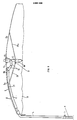
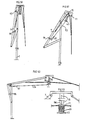
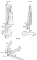
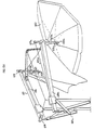
- FIG. 6 schematically show by way of non-limiting example the frame of the parasol during its implementation described above by Figures 1 to 5.
- the parasol is secured to the frame 1 by the tube 4: a hinge 5-5a commonly used for tilting the parasols, and slightly modified, makes it possible to fold the said parasol upside down.
- This articulation comprises a ring 5a which covers the axis of rotation 5 for its blocking.
- a bend 6 on the tube 4 facilitates the storage of the frame.
- the parasol's canvas is held in place with a strap so that it remains folded with the least amount of volume.
- the canvas is not shown in order to facilitate the clarity of the drawing.
- the parasol is brought into a practically horizontal position by means of the joint 5-5a.
- the frame of the parasol is supported by the radial arm 7 which is a tube, or any other suitable profile, the second end of which 7b comprises the articulation 5-5a, and the first end of which 7a supports the frame of the parasol.
- the umbrella frame is secured to the radial arm 7 by the whale 8 by means of the clips 9-9a-9b.
- the bundle of whales is maintained in this horizontal position by means of a hook 10 secured to the lower nut 11 and fixed to the chain 12 which is itself secured to the tube 4.
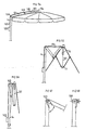
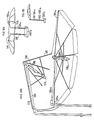
- the term “mast” is used to denote the element 15 connecting the reinforcing nuts, this element possibly being, as the case may be: short mast, cut mast, truncated mast, central mast.
- the user after having introduced the central mast 15 into the lower nut 11, brings the two nuts together to obtain the tension of the fabric, the lower nut remaining blocked by the appropriate spring 19.
- the articulation of the whale 8 and the counter whale 20 is close to a fixing clip 9 because the weight of part of the parasol is transferred at this point by means of the lower nut 11.
- the parasol then stabilizes in its intermediate equilibrium position shown in FIG. 8, which in this case is a pre-closing position; then the user hangs the assembly to the chain 12, and can leave his parasol in this position of non-use, or else fold it definitively by means of the joint 5.5a.
- the counter whale 20 is also advantageous, according to the invention, for the counter whale 20 to be of stronger cross section than the others by the fact that it supports part of the weight of the whole of the frame, so as to serve as the sole link between the lower nut 11 and the radial arm 7.
- FIG. 10 thus shows such a reinforced counter whale.
- This figure also illustrates a different embodiment in which the central mast 15 has been removed; the counter whale 20 keeps the entire reinforcement under tension by means of a system of clips 21.
- a spout 22 integral with the counter whale 20 helps the correct positioning of the lower nut 11 which would tend to be tackle obliquely due to the opposite action of the counter whales.
- a handle 23 secured to the lower nut will help the user in his maneuvers.
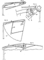
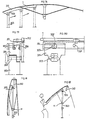
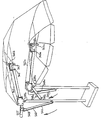
- the radial arm 7 and the nearest whale 8 are no longer integral but independent.
- the arm is secured to the truncated mast 15 by means of a part 26, shown in FIG. 13, comprising two bent branches 27 and 28 allowing the cut mast 15 to operate according to known methods; the assembly is articulated on an axis 29.
- FIG. 14 represents the parasol folded horizontally along the radial arm 7, the frame of the parasol being retained in this position by the means described above.
- the parasol remains in the equilibrium position shown in FIG. 15, and the canvas 17 which connects the whales momentarily holds the upper whale 8 against the radial arm 7.
- the mast 15 is oblique, the assembly forming a conical beam, allowing the user easy access to the interior of the parasol. It is then sufficient to block the mast 15 in its final vertical position by means of a clip 30, shown in FIGS. 13 and 16, this clip being secured to the radial arm 7 by a screw 31.
- FIG. 16 shows the parasol open and held in this position by the attachment of the mast 15 to the clips 30, and by the action of the spring 19 on the lower nut 11.
- the attachment of the mast 15 to the clips 30 may moreover be done before introducing the lower nut 11 into the mast 15.
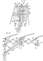
- the parasol comprises an upper nut 14 secured to a cut mast 15, and two lower nuts, so as to obtain an automatic opening.
- a first lower nut 11 is integral with a tube 32; a second nut 11 slides on the tube 32.
- the movement between the two nuts is created by a compression spring 33 surrounding the tube 32.
- 34a and 35a are secured respectively to the nuts 11 and 11 a as shown in the figure, there is obtained, under the action of the spring, a spacing of the two lower nuts which causes a spacing of the counter-whales.
- the articulation 36 being fixed on the radial arm 7, shown in FIG. 17, there is then simultaneously a thrust from the cut mast 15 and the opening of the ribs of the parasol.
- a spout 37 is provided at the entrance to this tube.
- FIG. 19 represents the open parasol
- the mast 15 is then introduced into the tube 32, and the two lower nuts have reached their extreme position relative to one another.
- a stop 38 fixed on the mast 15 limits the travel of the two nuts. For closing, it suffices to bring back manually, or by any suitable means, the lower nut 11a against the vertical mast 4.
- the spring 33 is then under tension and the two lower nuts are lowered.
- FIGS. 20 to 22 the upper 14 and lower 11 nuts are connected together by a system of telescopic tubes 39.
- FIG. 20 represents the parasol in its horizontal position of non-use;
- FIG. 21 represents the parasol in an equilibrium or pre-opening position, after the release of the lower nut 11.
- FIG. 22 represents the parasol in the opening position.
- the telescopic assembly was then closed so as to obtain a very short mast in accordance with the invention.
- a spring 40 integral with the narrowest part of the telescopic assembly, after its passage in the lower nut 11, moves away and retains the telescopic mast in its vertical position and thus fixes the armature in its open position. To close the parasol, simply pull on the lower nut 11 to fit the spring into the tube system.
- FIGS. 23 to 26 show an embodiment in which the lower nut 11 makes a short path relative to the upper nut.
- Figure 23 shows the parasol in its non-use position folded against the radial arm 7.
- a cut mast 15 is secured to a top nut 14 of known shape, having a cavity 41 shown in Figure 26.
- the lower nut 11 is housed in this cavity.
- the counter whale 20 is fixed at 42 to the radial arm 7 and at 43 to the lower nut 11.
- the upper nut 14 is articulated on the radial arm 7 according to the joint 13. It is expected that the counter whale 20 is more as long as part 42-13 of the radial arm.
- the assembly When the whales are released, the assembly is arranged in a conical beam as shown in FIG. 24.
- the user can then easily reach the flexible handle 44 secured to the lower nut 11, and pull on the handle.
- the counter whales then move away from the whales and thus open the parasol.
- the upper nut 14 pivots on the articulation 13.
- a suitable spring 19 blocks the lower nut, after being retracted in its passage.
- a stop 45 prevents the lower nut from coming out of the mast.
- the spring 19 is pressed while simultaneously pushing the lower nut onto the mast 15.
- the whalebone bundle folds against the radial arm and remains hooked in the rest position by means of a loop 46.
- the medial arm acts as a counter whale for the frame, the lower nut 11 being articulated at the end of the radial arm 7.
- the upper whale 47 is connected to the radial arm at the near its end 48.
- the upper nut is secured to a cut mast which slides in the lower nut 11.
- Figure 27 shows the device in the pre-opening position
- Figure 28 shows it in the open position.
- Figures 29 to 33 show an embodiment relating to the modification of the counter whales.
- Figure 29 shows a closed frame.
- FIG. 30 represents this parasol frame adapted on a radial arm 7.
- FIG. 31 shows, in a closer view, the frame in the closed position.
- Each counter-whale is in two unequal parts 49 and 50, connected to each other by common articulations, in particular, here, by a torsion spring 51.
- the purpose of each spring is to facilitate the opening of these two parts so as to make them rectilinear, that is to say that the parts 49 and 50 are practically in line with one another in the open position shown in FIG. 30.
- the counter whale 49-50 connecting the lower nut and the radial arm can be fixed on the radial arm as described in the previous embodiments.
- each whale comprises a part 53, shown in FIG. 32, on the end of which is fixed a cable 54. All the cables 54 are connected by a meeting point to a cable 55 which serves as cable reminder to close whales.
- the upper and lower nuts are connected by a hollow tube or cut mast 15, a return pulley ensuring the return of the cable 55 to the radial arm and the user.
- a torsion spring 56 shown in FIG. 30, which facilitates opening; this spring is also not shown in the other figures for clarity of the drawing.
- the folding of the parasol is done along a practically horizontal radial arm, which is connected to a vertical mast eccentric at the periphery of the parasol.
- the positions of non-use of the parasol are either horizontal or upside down, and handling must be carried out to obtain the use of the parasol.
- these handling operations are reduced so as to make it possible, from simple maneuvers, and external to the parasol, to open and close without having to manipulate any cursor or any other means of action. on whales. Opening and closing is facilitated by using the parasol's own weight to obtain the pre-opening.
- two practically opposite movements are created simultaneously, one for deploying the radial arm from a vertical position of non-use to a horizontal horizontal position, and the other simultaneous movement for opening the whales and their voltage.
- a special feature of the invention is to highlight these opposite reactions, one of the weight of the entire frame which, by tilting on its eccentric mast creates a significant weight, the other reaction being the opening of the counter-whales opposing the weight of the entire radial-whale and canvas arm.
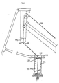
- FIGS. 34 to 42 An embodiment having such an operation is illustrated by FIGS. 34 to 42.
- an articulation system comprising an intermediate vertical mast 57 on which the cam 56a is adapted are connected by a common axis 58 two arm links 59-60.
- the other end of the rods 59 and 60 is connected by the axis 61 to the radial arm 7 of the parasol.
- FIG. 37 represents the right end of the rods connected by the axis 58 to the mast and the left end connected to the support 7 by the axis 61.
- the radial arm 7, in this embodiment, comprises a cavity 62, as represents it in FIG. 39. In this cavity slides a special part 63, represented in FIGS. 38 to 42. This part plays two roles for the radial arm 7, allowing it to roll and pivot at the same time.
- the part 63 comprises rollers 64 mounted at the end of the mast 57, shaped to be introduced into the cavity 62.
- FIG. 40 represents the radial arm 7 in the vertical position of non-use;
- Figure 41 shows the same arm in an intermediate position, and
- Figure 42 shows it in a horizontal position. It is thus seen that the rollers 64 allow the passage of the support 7 and its chan orientation orientation, passing from the vertical position to the horizontal position.
- the radial arm 7 is tilted which remains in abutment on the mast 57 by means of the part 63.
- a cable 67 is secured to the mast 57 by the fixing 68, and the movable nut 11. It is returned by the pulley 69 of the lower nut to the fixed point 68 of the mast.
- the cable pulls on the lower nut simultaneously with the advancement of the radial arm, until the whales are fully opened.
- the lower nut 11 fits onto the cut mast 15 at the end of movement.
- the tension of the fabric is obtained by forcing on the links 59-60 in order to secure them to the mast 57 by a clips 71.
- the cut mast 15 is articulated on the radial arm 7 by a yoke 26 and a transverse axis of rotation disposed at the - below the pulley 69.
- a stop 70 limits the tilting of the mast (Fig. 36).
- the counter whale 20 can be deleted; the whale 8, integral with the canvas, is rounded thanks to the other whales that stretch the canvas.
- Figures 43 and 46 illustrate another embodiment using articulated counter whales.
- the upper nut 14 is articulated on the radial arm 7 of the parasol frame.
- a cut mast 15 of fixed length connects the two nuts 11 and 14.
- the device comprises an articulated mast comprising a fixed part 72 and a tubular part 73, articulated together by the axis 74.
- the articulation between the arm 7 and the tubular part 73 takes place by a transverse axis 75.
- the radial arm no longer has support in its upper part.
- a tension spring 76 shown in FIG. 44 is installed in the movable tube 73, connected by a cable 77 to the movable arm 7 at a point 78 as shown in the figure.
- the cable passes on the axis of the articulation 75 and thus exerts an opening tension of the two parts.
- the flexible handle 79 exerts a movement from bottom to top, movement facilitated by the action of the spring.
- the articulated counter-whales such as the counter-whale 80, are articulated as in the embodiment shown in FIG. 31 by springs which cause them to open.
- the final opening position shown in FIG. 45 is stabilized by a lever 81, the upper end of which comprises a cavity 82 intended to be clipped onto a ball 83 secured to the radial arm 7.
- This lever is fixed to the arm 73 and comprises a double branch, as shown in FIG. 46, so that the cavity 82 to be clipped is in the axis of the support 7.
- a rod 84 extending the mast 72 is fitted a clips 85 receiving the tubular part 73 in a vertical position.
- the user pulls the flexible handle 79, releasing the tubular part 73 of the clips 85 and, while holding the handle, releases, by the lever 81, the parts of the radial arm 7 and arm 73; the spring 76 exerts a retaining force on the folding of the parasol.
- the counter-whales 80 are returned by the cable 86 shown in FIG. 45.
- This cable is connected to the whales by intermediate cables 87, as shown in the figure.
- the cable 86 is connected to the mast at 88.
- the simultaneous recall of the whales, with the closing of the parasol is ensured by the position of the point 88 on the rod 84.
- the cable being of a constant length, continuing to press the flexible handle 79, the parasol is closed.
- the position of the return pulley 89 makes it possible to adjust the simultaneous operation of the positioning of the radial arm with the maneuvers of the whales.
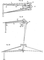
- a common type reinforcement is adapted to a radial arm, as shown in FIGS. 47 to 49.
- a spring 76 is housed in an articulated tube 73 intended to facilitate the opening operations of the radial arm 7 and of the tube 73.
- a cable 90 is secured to the mast 72 at a point 91 and to the lower nut 11 passing through the necessary references as shown in the figures. The more the end 75 moves away from point 91, the more the lower nut 11 approaches the cut mast 15.
- FIG. 49 shows the parasol completely open, after the lower nut 11 has been fitted into the cut mast 15.
- the open position will be stabilized by the support 92.
- the articulation 74 is shaped so as to remain in alignment with the mast 72.
- the lengths "x" and "1" must be equal.
- the articulated mast system is adapted to a frame whose lower nut describes a short path on a truncated mast.
- FIGS. 50 to 53 illustrate such an embodiment: the mast system explained above is used in the embodiment of FIGS. 23 to 25.
- the simultaneous movement of the positioning of the parasol and the opening of the whales is obtained by connecting, by a cable 93, the lower nut 11 to a special piece 94 sliding in the radial arm 7.
- the piece 94 is driven and pushed towards the end of the radial arm, which has the effect of pull the cable and the lower nut.
- the central mast cut 15 includes a slot 95 to allow the passage of the attachment 96 securing the lower nut and the cable.
- This fixing is manufactured to be able to best transmit the tension of the cable to the lower nut 11.
- a tension spring 97 allowing its elongation at the end of the stroke while continuing to exert traction on the lower nut. Its strength is therefore studied so that the cable pulls the lower nut before it lengthens.
- a system of clips 98 ensures the locking of the radial arm in the deployed position.
- FIGS. 54 to 58 illustrate an embodiment in which the radial arm is placed above the canvas surface of the parasol.
- the common part of the radial arm with a whale of the armature is limited to the part 100 furthest from the fixed support, the other part 101 of the radial arm being articulated on the vertical mast 4, the two parts of the radial arm being articulated between them by a transverse axis 102.
- a cable 103 connects the end 104 of the radial arm to a handle 105 which slides on the vertical mast.
- a second cable 107 connects the vertical mast 4 to the lower nut 11 of the counter-whales according to the means used in the previous embodiments.
- the handle 105 going up on the mast, releases the two parts 100 and 101 of the radial arm which opens. Simultaneously, the cable 107 pulls the lower nut upwards and the ribs open. At the end of the race, the lower nut fits on the cut mast 15 as in the previous embodiments.
- To close the assembly simply lower the handle 105; the parts of the radial arm fold back and the frame, due to its weight, also closes.
- the invention provides for adjustments to the radial support and its integration into articulated systems.
- FIGS. 59 to 61 it is possible to provide a giant spider formed by the radial arm 7 and by a counter whale 20 which would have been extended to adapt it by an articulation 108 to the fixed vertical mast 4.
- This spider thus formed is articulated in the middle at 109.
- the whale arm-radial arm 7 is integral at its upper part with the upper nut 14 and, at its lower part, with a handle 110 sliding on the vertical mast 4.
- a cable 111 connects a fixed point 112 of the mast 4 to the lower nut 11 by the appropriate necessary references as shown in the figures.
- FIG. 61 schematically represents the adaptation necessary for the counter whale 20 to cross the surface of the fabric.
- the radial arm may consist of two branches 7a-7b in the middle of which the counter whale operates.
- the fabric 17 is fixed by stapling 113-114 on the edges of the branches 7a and 7b forming the radial arm. Note the position of the neighboring whales 115 and 116 directly connected by the fabric to the branches 7a and 7b of the radial arm.
- lever arms can be used to make it easier to operate parasols of all sizes.
- the embodiment shown in Figures 62 to 65 allows such improvements: it includes the same elements as the embodiment shown in Figures 34 to 37, with in addition an extension of the rods 59-60 on the other side of its articulation point 58 on the vertical mast.
- the extension thus formed allows the adaptation of a tension spring 117 between the end 118 of the extension and a lower fixed point 119 of the vertical mast 4.
- the spring in the non-use position, shown in FIG. 62, the spring is practically parallel to the rods 59-60 and therefore its action is neutralized.
- all the force of the spring is used to the maximum when it pulls in overhang, as shown in FIG. 63, and provides the user with better comfort either for opening or for closing.
- Appropriate means, already described, will allow the parasol to be fixed in its final open position.
- FIGS. 66 to 69 the radial arm is developed from a set of vertical telescopic masts.
- FIG. 66 represents two vertical masts 305-306 adapted on a base 307; a handle 308 suitably adapted to the two masts makes it possible to develop the telescopic tubes 309 and 310 in a second position which are fixed in this position by the pin 311 shown in FIG. 67.
- FIG. 68 there is shown the open umbrella.
- the radial arm 7 is tilted from a vertical position as shown in FIG. 66 to a practically horizontal position as shown in FIG. 68 by developing the last part 314 of the assembly telescopic.
- This by tie is secured to the radial arm 7 by a suitable articulation 315.
- the movement causes the radial arm 7 to slide on a piece 316 adapted to the end of the other part 317 of the telescopic mast 306.
- the piece 316 is rounded to allow tilting of the radial arm.
- FIG. 69 represents, in a section AA of FIG. 68, the part 316 adapted in the radial arm 7.
- the pin 311a secures the two tubular parts 314 and 317.
- the positioning of the radial arm simultaneously causes the parasol to open by means of a cable 318 connected to the lower nut 11 and to a fixed point 320 of the vertical mast 305 passing through pulleys of appropriate referrals.
- the length of travel of the lower nut “p” in FIG. 66 will be equal to or slightly less than the travel “q” of the last part 314 of the telescopic assembly 305.
- the articulation 315 can be provided with a clamping means.
- the positioning of the radial arm and the opening of the parasol can be obtained simultaneously from a simple rocking movement of the radial arm on a vertical mast.
- Figures 70 to 73 show such an embodiment.
- FIG. 70 represents the user who has just positioned the mast 322 on the peak 323 secured to the base 324.
- the radial arm 7 is then extended by the part 326, and the two parts are articulated by a known articulation device 327.
- the radial arm is secured to the vertical mast by a suitable articulation 328.
- Figure 71 shows the beginning of the parasol's opening movement.
- the radial arm rocks on the joint 328 and the user controls the downward movement under the effect of the weight of the parasol by the extended part 326 of the support.
- a cable 329 connecting the lower nut 11 of the counter-whales to a fixed point of the mast 322 causes the umbrella frame to open, as described in the previous variants with equal lengths "r and" s ".
- FIG. 72 represents the parasol in its fully open position with tension of the fabric, all the easier since its own weight contributes to this tension.
- a stop 331 secured to the mast 322 prevents the radial arm from continuing to descend. It then suffices to open the articulation 327 of the two parts of the radial arm, as shown in FIG. 73, and therefore to clip the extended part 326 onto the mast 322 by the clips 332.
- the cable 329 is guided along of the radial arm 7 and along the elongated part, in particular by guides 333-333a on each side of the articulation 327.
- guides 333-333a on each side of the articulation 327.
- One of the advantages of the invention is the eccentric position of the vertical support peak of the whole parasol, this support peak being fixedly at the periphery of the parasol. It is then advantageous to be able to vary the position of the vertical mast, from its eccentric position to a central position by means of a variable radial support. It is thus possible in particular to propose three embodiments allowing these variations.
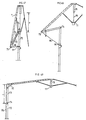
- Figures 74 to 77 show an example of an extendable radial arm.
- the radial arm is composed of cross-pieces 334 here folded.
- the vertical support mast 335 is integral with a base, not shown.
- Figures 75 and 76 show schematic top views showing the positioning of the braces relative to the vertical support mast 335 relative to the central mast 15.
- Figure 75 shows all of the closed braces
- Figure 76 shows the same set in a position of extension of the braces.
- the vertical mast 335 is secured to the cross braces by a fixed axis 337 and by a sliding axis 339.
- the cut mast 15 is secured to the braces by a fixed axis 338, and a sliding axis 340.
- a counterweight 342, shown in FIG. 77, can be added to the set of crosspieces, moving away from the eccentric pole at the same time as the cut pole in order to oppose the weight of the parasol and thus balance the whole .
- FIGS. 78 to 82 represent another embodiment in which the radial arm 7 is secured to the vertical mast 353 by means of a part 354.
- This part 354 is articulated and clamped to the vertical mast 353 by an axis 355 shown on FIG. 79.
- This axis also functions as a means of clamping the part 354 on the mast. 353. This gives the possibility of orienting the radial arm 7 relative to the vertical mast 353.
- part 354 and the radial arm 7 are secured by means of a male-female assembly shown in FIG. 79.
- the radial arm can slide on the male part 356 of the part 354 and thus the position can be varied. from one to the other.
- the part 354 and the radial arm are then joined together by means of a screw 357 which enters the holes 358-359 of the radial arm.
- FIG. 78 represents three positions of the radial arm relative to the vertical mast 353: an extreme position, an intermediate position and a practically central position.
- FIG. 81 represents the frame of the parasol in the closed position, the clamping screw 355 being loosened and the part 354 in the central position. So by his own weight, the frame folds up against the vertical mast in accordance with the invention.
- FIG. 82 represents the movement of opening of the frame from the outside. The user will grasp the peripheral end of the radial arm 7 and cause it to perform a rotational movement around the axis 355, which will have the effect of half-opening the whales.
- the displacement of the central mast relative to the fixed vertical mast can be obtained by using a telescopic radial arm.
- This embodiment is illustrated in FIGS. 83 to 87.
- the telescopic tube 361 supports the frame by its articulated upper nut 14.
- the telescopic assembly 361 is itself articulated to a fixed part 364 secured to a vertical mast 365, by an axis 366.
- a torsion spring 367 is adapted according to the known methods between the two parts 361 and 364 so as to create a force which arranges the telescopic part in a horizontal way.
- a cord 368 is fixed to the telescopic tube at a point 369, and makes it possible to control the action of the torsion spring 367 and therefore to arrange this telescopic assembly either in a vertical position for closing, or in a horizontal position for the opening.
- FIG. 85 represents an intermediate position in which the armature forms a beam.
- the two parts 364 and 361 become perpendicular and are secured in this position by any known method; then adapt the lower nut 11 in the cut mast 15 secured to the upper nut 14.
- FIG. 86 represents the open parasol supported by the vertical pole 365 in a practically central position. But the user has the possibility of stretching the telescopic assembly and thus of moving the central cut mast 15 away from the vertical support mast 365 which will be offset at the periphery. For closing, it is sufficient to repeat the reverse action on the operating devices and pull on the cord 368 to obtain a vertical position of non-use, and the cord will be attached to the mast on a special piece 376.
- a first solution consists in providing a central mast long enough to allow guiding the nuts throughout its course.
- the mast may be of fixed length and relatively short; on the other hand in the case of a long stroke of the nut it may be preferable to connect the two nuts by a central telescopic mast.
- FIG. 88 illustrates an embodiment of such means, in which the truncated mast 15 has at its lower end a rounded part 199 comprising a central bore 200 in which the cable 201 slides. The rounded part comes to nest in a movable nut 202 relatively long.
- An inner ring 203 slides in the central bore 204 of the movable nut, and has a central perforation 205 through which the cable passes.
- the ring 203 is pushed upwards by a spring 206 of suitable length up to the orifice of the bore 204.
- a spring 206 of suitable length up to the orifice of the bore 204.
- the cable 201 tends to present one opposite the other. central bore 200 and the perforation 205.
- the ring 203 is pressed in by the truncated mast during interlocking.
- the simplest embodiments of the present invention are suitable for use in beach umbrellas planted in the sand.
- the central pole is particularly troublesome in the case of common parasols, but thanks to the offset pole system, the space under the parasol is completely free.
- Figures 89 to 92 illustrate such use.
- a canvas 403 helps to cut the wind, and the parasol is stabilized in the sand by a particular foot, represented in FIG. 90, comprising in addition to the classic peak 401 a second peak 402, the two peaks being secured at point 401 a.
- the user's attention will be focused on the adaptation of this support in the sand: it is necessary to perform a back-and-forth movement in the plane defined by the two peaks 401-402 as indicated by the double arrow of FIG. 90, and this movement is simultaneously coupled with a push towards the ground according to the arrow in FIG. 90.
- Figures 91 and 92 show a variant, allowing easier transport.
- the main peak is composed of two tubes of different sections 404 and 404a; the peak 405 is introduced into the peak 404 via the slide 406 which abuts on the tube 404.
- FIG. 93 the lever 269 actuates the radial arms 270-271 by means of a common cross member 272 articulated in the lower part to the lever 269 by an articulation yoke 273.
- This lever is adapted to the mast 274 by an axis 275 and actuated by a tension spring 276.
- the radial arms 270 and 271 will be chosen in accordance with the invention with a cavity in order to allow the sliding of special pivots as shown in FIGS. 94 and 95.
- the radial arms can pivot at their lower ends on axes 277 and 278, as represent it in FIGS. 93 and 100, integral with the crosspiece 272.
- the mast 274 is split in its upper part into two branches 274a-274b.
- each support 270 and 271 can be supported thereon by special articulations, respectively, the pivot 279 for the support 270 and the pivot 280 for the support 271.
- the articulations can comprise casters 281-281 a connected by an axis 282 -282a secured to a support 283-283a.
- the joints can also rotate relative to the branches 274a-274b as shown by the double arrow in FIG. 95.
- the radial arms 270-271 can then move in all directions, in particular in the plane that they form between them, and deviate from a position parallel to a perpendicular position. Indeed, under the action of the common lever 279, the radial arms are pushed on the joints 281-281a, while passing from a vertical plane to a horizontal plane; their upper ends are simultaneously spaced from one another by the rotation of the supports 283-283a until the two arms are practically perpendicular in the fully open position.
- FIG. 99 shows in profile all of the two parasols at rest, the radial arms being retained by a flexible handle 286 on the handle 284 according to all known methods.
- the handle 284 and the mast 274 are offset to allow maneuvering.
- the handle 284 is integral with the concrete base 285.
- the flexible handle 286 is used to control the opening movement to prevent the spring from suddenly expanding, and to serve as a return means for the radial arms when closing.
- all kinds of parasol mounts can be adapted to the radial arms, in particular those described in the previous embodiments.
- Figure 101 shows a three quarter rear view of two fully open parasols actuated by the same lever.
- the two radial arms 270-271 are below the surface of the fabric, and they are visible in this figure because the fabrics 287 and 288 are fictitiously cut to allow the device to be understood.
- Two wheels 289 are also adapted on the base 285 to facilitate handling of the assembly.
- the embodiments which follow relate to eccentric parasols comprising a one-piece canvas held and stretched by several partial frames.
- two masts 501 and 501a are connected to two peaks 502 and 502a by clamping means 503-503a comprising an eccentric lever adapted on the outer tube and making it possible to tighten the inner tube.
- the peaks 502 and 502a are shown secured to a concrete base 502b for holding the assembly.
- two radial arms 504 and 504a are secured to a frame formed by two vertical masts 501-501 a by means of an articulation system composed of a ring 505-505a opening or closing the articulation 506- 506a horizontal axis.
- the radial arms 504-504a comprise at their first end yokes 507-507a intended to ensure by means of the axes 508-508a the articulation of cut central masts 509-509a.
- These truncated central masts are secured to whales by means of upper nuts 510-510a in a conventional manner.
- Each of the nuts 510 and 510a comprises only the ribs necessary to ensure a half-circumference of the parasol, with possibly one or two ribs for the maintenance of the central part.
- the whales 511 to 515 are shown delimiting four slices of the canvas of half a parasol.
- the nut 510a ensures the operation of the whales 51 ta to 515a making up the other four sections of the fabric.
- the two canvas halves are connected together by sewing to the central part 516 in canvas of rectangular shape.
- the radial arms 504-504a are arranged to be divergent, so that the distance of the cut masts is greater than the spacing of the support masts 501-501a.
- the tension of the fabric is then ensured when the two sliders 517 and 517a slide on the masts 509-509a and are retained by the retractable lugs 518-518a of known type.
- the tension of the central part of the fabric is ensured by the spacing of the radial arms.
- Clips 519 and 519a ensure the locking of the central masts in the deployed position at the end of the radial arms.
- Figure 106 shows the assembly in its first closing phase.
- the slider or lower nut 517 is detached from the truncated central mast 509 by releasing the tension of the lug 518.
- the whole of the fabric is then relaxed, and the released part is arranged in a conical half-beam.
- the other part remains in half-circumference but the whales relax and are practically straight because there is no more tension. Only the extreme whales 515a, 51la undergo a slight tension coming from the right part, which tends to retain the half-cone formed by the bundle of whales 511 and 515.
- FIG. 107 represents the second half in the conical position, after having released the lower nut 517a from the lug 518a.
- the weight of the central part of the canvas tends to bring the two half-cones closer together.
- each mast 501-501a with its peak or lower part of the frame; the levers 503 and 503a actuate an eccentric which is integral with them so as to enter a reservation 519-519c provided in the masts 501-501a.
- the levers 503-503a are loosened, the masts 501-501a are nevertheless retained on the peaks 502-502a by the axes 520-520a secured to these peaks and allowing the rotation of the masts 501-501a in the peaks.
- FIG. 109 represents the device after rotation of the peaks 501a-501 for bringing the heads of the parasol closer, the half-frames being brought back to the closed position by hooking the lower nuts 517-517a to the peaks 501-501a, for example by a solid hook of the lower nut retained by a chain secured to the mast.
- the rings 505-505a are slid to release the joints 506-506a, which allows the tilting of the radial arms 504-504a against the peaks 501-501a.
- Figure 111 there is shown the mode of transport of the device in which the user can easily remove the two umbrella halves of the peaks, by the fact of their approximation on the same base 502b.
- the peak clamping system can prove difficult to execute for large parasols.
- FIG. 112 represents an embodiment in which the ends of the radial arms are separated by adapting, on the truncated central masts 509-509a, sockets 521-521a onto which tube outlets 522-522a intended to receive a telescopic assembly have been welded 523 formed of two tubes, one of which 524 can slide on a larger 525.
- the telescopic assembly is adapted in tubes 522-522a by means of special slots 526-526a.
- the sockets 521-521a rest on the axes 521 b-521 c which pass through the cut central masts, preventing them from escaping from these masts without interfering with rotation on the cut masts.
- FIG. 113 shows the detail of the construction of the telescopic assembly 523, in the stretched position to spread the central masts 509-509a as far as possible. This determines the tension of the fabric of the two half-parasols, and a fixing bolt 527 tightens the two tubes in a fixed position to lock them.
- the spacing of the central masts by the telescopic bar 523 is accompanied by a rotation of the rings 521 and 521 a on the central masts.
- FIG. 114 represents the action of the telescopic assembly 523 causing the rotation of the masts 501 and 501a.
- the screw 527 which locks the two sliding tubes 524 and 525, the entire structure of the parasol is blocked. This prevents the force of the wind from causing the system to rotate.
- the two masts 501-501a can rotate in the tubes 530-530a joined together by a fixed lower element 531.
- the assembly is carried by a large diameter pick 532, itself -Even being able to turn in a sheath tube 533 having a clamping means 534 in order to fix the whole of the parasol in different positions necessary for sun protection.
- This sheath 533 is secured to the concrete base 535 by any appropriate means.
- the device comprises two vertical masts 536-536a fixed on a base 537. At the top of these masts is provided a housing, for example by suitable parts 538 and 538a, allowing the passage of the radial arms 539 and 539a by sliding. These parts may include rollers necessary for the proper sliding of the radial arms, and are further articulated at 539b and 539c to follow the progressive inclination of the arms during their deployment.
- a suitable yoke 540-540a supporting the cut central mast 541-541a and articulated on these masts as previously described.
- Cables 542 and 542a are also shown connecting the sliders 543-543a or lower nuts of the counter-whales to the fixed point 544-544a returned by pulleys 545-545a secured to the central masts.
- the cables allow the automatic deployment of the whales around the truncated masts under the action of the deployment of the radial arms, so as to reduce the number of operations necessary for the opening and closing of the parasol.
- Connecting rods 546-546a connect the second end of the radial arms to the frame as shown in FIGS. 116 and 117 to lift the second end of the radial arms during their deployment and place them in a horizontal position.
- the connecting rods 546-546a and the radial supports determine planes which form a certain angle between them so that, when the radial supports are in the deployed position, they are divergent in order to stretch the fabric.
- this angle is not too open, or that the vertical masts are not too close together, so that the rods can be maneuvered alternately or at the same time without touching.
- Two tubular elements or the like 547-547a are articulated on the axes 539b-539c, and comprise cylindrical elements 548-548a in sliding material such as polyvinyl chloride, fixed perpendicular to the edge elements and intended to ensure a sliding, in particular on their respective radial support, at the time of the operation of the passage from the vertical to the horizontal.
- the elements 547 and 547a then serve as a lever for blocking the reinforcements.
- Figure 117 the end of the movement is shown; the connecting rods 546 and 546a no longer ensure the advance of the radial arms more easily due to the tension of the fabric.
- Slits 549-549a are formed on the outside edge of the connecting rods 546-546a so that the cleats are housed there and blocked there.
- the lever 547 is about to slide on the connecting rod.
- the other lever 547a has already exerted its pressure against the connecting rod and is in its locked position.
- the fictitious planes defined by the radial arms and the connecting rods are no longer fixed. In order to improve the performance of the device, and in particular to reduce the spacing of the vertical support masts, these planes will be made mobile.
- FIG. 118 shows, by way of example, this other embodiment.
- the part 538 which ensures the sliding of the radial arms, as well as the yoke 546b on which the connecting rod 552 is articulated, are mounted on a tube 550 which acts as a sheath relative to the carrier tube 536; rotation around the tube 536 is thus allowed by virtue of the part 551 made of an unalterable material such as polyvinyl chloride, secured to the tube 536 at its end.
- FIG. 119 represents an embodiment in which the whole of the parasol is mounted on vertical poles fixed to the concrete base as described above.
- Tubular sleeves 550-550a are adapted on the masts 536-536a which abut on the parts 551-551a secured to the tubes 536-536a at their upper ends.
- the radial arms include at their ends the central masts, and the corresponding nuts for the operation of the whales. The whales are opened simultaneously with the movement of the radial arms.
- One adapts on the connecting rods 552-552a a telescopic assembly 553 formed by a tube 554 which slides in another tube 555.
- the two tubes are secured to the connecting rods, or to the radial arms near their second end, and are provided with a operating handle 556 integral with the tube 555 which makes it possible to lift the entire frame of the parasol.
- the radial arms are thus brought back parallel from their vertical position to their horizontal position of use.
- the semi-circumferences of the parasol are then deployed under the effect of the pull of the cable exerted on the lower nuts, the central part of the fabric being however relaxed.
- the tension of the central part of the fabric is obtained by spreading the ends of the radial arms.
- the divergence of the two radial arms is represented by means of a clamping system given by way of example.
- hooks 557-557a are provided which are fixed to the axes 558-558a, axes which join the articulations of the radial arms with their support mast but which are extended to provide for the adaptation of these hooks.
- a nylon cord 559b is secured to these hooks according to known means, and passes through the orifices of the rings 559-559a secured to the corresponding connecting rods.
- Part of the cord 559c is also fixed to the plate 560 through which the other piece of cord 559b passes.
- FIG. 121 represents another embodiment making it possible to ensure the divergence of the radial arms simultaneously with their deployment.
- the two radial arms 561-561 a are substantially parallel in their vertical folded position.
- Each radial arm includes a return 562-562a perpendicular to its second end. These returns are articulated by axes 563-563a to a tubular bar 564 of fixed length so that the spacing of the second ends remains less than the spacing of the housing of the frame to cause the divergence of the arms during their deployment.
- FIG. 122 represents this tubular bar 564 secured to the connecting rods 565-565a by axes 566-566a allowing the rotation of the connecting rods and of the tubular bar 564 during the movement of the connecting rods from top to bottom.
- a handle 567 is integral with the tubular bar to allow the two radial arms to be lifted together. But when the connecting rods approach the vertical masts 568-568a, the radial arms pivot on their axes 563-563a and cause the rotation of the upper parts 538-538a articulated by axes to the tubes 570-570a which can rotate in the tubes 568- 568a serving as vertical support.
- Stops 571-571a formed by axes passing through the tubes 568-568a support the tubes 570-570a while allowing them to pivot.
- FIG. 123 represents in close-up a half of the system with a clamping means constituted by a lever 572 articulated to an axis 573 secured to the tubes 568.
- a loop 574 adapts in the hook 575 secured to the connecting rod. By pressing the lever, the loop is pulled which tightens the closure and locks the device. The same operation repeated on the other rod makes it possible to tension the parasol.
- Figure 124 shows this locking device in the open position.
- FIG. 125 another embodiment has been shown making it possible to improve the spacing tension of the radial arms, in particular allowing the production of large parasols.
- two arms 576 and 576a hinged together by an axis 577 are fixed to the radial supports at their upper end by hinges articulated 578-578a.
- the two arms form an acute angle between them, the apex of which is directed towards the first ends of the radial arms.
- a cable 579 is fixed at two points 580-580a of each of the two arms and is connected to a cable 581 itself secured to the masts 550-550a.
- FIG. 126 represents the action of the cable 579 opening the angle of the arms 576-576a and pushing the radial arms outwards until the desired spacing is obtained at the tension of the fabric.
- the displacement of all of the radial arms may be limited in their rotation relative to the mast 536-536a by means of the rods 583-583a integral with the tubes.
- the parts 584-584a integral with the tubes 550-550a stop the tubes in the event of lateral movement of the assembly against the rods 583-583a.
- FIG. 127 represents the adaptation of a hoist 585-585a secured on one side to a bar 586 which connects the two vertical masts and on the other side by a hook 587 connected to the handle 556 of the telescopic tubular assembly 553. Bar 586 is mounted appropriately so as not to impede the rotation of the vertical masts.
- FIG. 128 the parasol is shown in the fully open position, after the user has pulled on the rope 588 of the hoist.
- the two parts 585 and 585a making up the hoist have moved towards each other.
- the cable 589 pulls on the arms 590-590a, thus spreading the radial arms.
- the user traps the rope in a cleat 591 to lock the device.
- FIG. 130 shows an embodiment in which a common radial arm 604 is extended by three secondary radial arms 605, 606 and 607.
- the secondary radial arms 605 and 607 move away from the central arm 606 according to methods previously described by means of articulated arm assemblies 608-609 actuated by cables.
- FIG. 131 represents another embodiment in which the parasol comprises a single radial arm on which secondary arms are articulated.
- the secondary arms On the radial arm 610 are joined the secondary arms in the form of crossbars 611, joined at a fixed point 612 of the radial arm and at a point 613 secured to the ring 614.
- the ring has a tubular profile of larger section than the arm 610 and slide on this arm.
- the actuation of the cross arms is obtained by way of example by means of a cable 615 connected to point 616 of the sliding part and in 617 to the yoke 610a of the device.
- the cable is stretched and, thanks to the pulley 618 secured to the radial arm at its end, the sliding ring is brought closer to the fixed point 612 and the opening of the cross arms.
- the two cut masts 619 and 620 are then separated from each other and help to stretch the canvas.
- the sliders or lower nuts 621-622 are caused to be housed in the cut masts 619-620 by the action of cables 623-624 secured to the yoke 610a. This gives the general tension of the fabric, not shown in the figures for reasons of clarity.
- the cut masts 619 and 620 are connected to the ends of the braces by an axis which allows their articulation.
- Stops 625 and 626 stop the masts in their position perpendicular to the ground necessary for the correct arrangement of the parasol.
- the cables 615, 623 and 624 are of an appropriate length so that the assembly operates in a synchronized manner.
- a closing device 610b makes it possible to secure the vertical mast and the connecting rod in an open and tensioning position of the fabric to lock the device.
- the cables 623 and 624 are connected to the first end of the radial arm and no longer to the yoke 610a, and the sliders are pulled during the opening of the braces, that is to say during the race of the ring 614 on the radial arm. It is then necessary to choose a sufficient number of braces so that the spacing of the head, or central mast cut, with the radial arm corresponds to the distance of the cursor from its cut mast.
- Figure 132 shows the device in its non-use position.
- the support 610 is practically vertical.
- a return spring 627 facilitates the folding of the braces.
- the parasol heads can be separated by a brace arm device connecting them directly to each other.
- the device consists of a radial arm 628 associated by a suitable articulation 629 with a cut mast 630.
- the set of crosspieces is integral with the mast cut by fixed points 631-632 and by points 633-634 integral with a sliding ring 635 sliding on the mast cut 630.
- the other cut masts 636 and 637 are secured to the cross-bracing system by fixed points 638 and 639 and by mobile points 640-641 fixed to sliding rings 642-643.
- the sliders 644, 645 and 646 will be housed in the respective central masts under the action of the cables 647, 648 and 649 when the radial arm advances in the yoke 610a.
- Figure 134 shows the device in the fully open position.
- the cut masts move apart and thus stretch the canvas simultaneously with the opening of the whales.
- a stop 650 limits the stroke of the cut mast and stabilizes the device in a vertical position under the action of the cables.
- the cables 647, 648 and 649 are of an appropriate length to act together on the respective sliding rings.
- the cables 647 and 649 can secure to the mast 630, and only trigger the opening of the cross-pieces at the moment when the cursor 645 actuates the ring 635.
- the number of cross-sections depends on the stroke of the ring so that there is sufficient length to pull the sliders 646 and 647.
- the articulation of the truncated masts on the first ends of the radial arms can be carried out on the upper nuts themselves. In this case one can assimilate one of the whales with the radial arm; that is to say that the radial arm acts as a whale, or that the radial arm is secured to the whale ensuring articulation with the truncated mast.
- This arrangement can be used in all the embodiments described above to ensure the permanent maintenance of a radial portion of the fabric in the vicinity of the radial arm.
- a radial portion of the latter is constantly maintained in the vicinity of the radial arm, in particular by the weight of the fabric when it is relaxed.
- FIG. 135 illustrates an embodiment in which the sliding nuts 676-676a have a short and inverted stroke compared to the previous embodiments: the inclination of the counter-whales is reversed, the folding of the canvas is obtained by bringing together nuts from one another, while the distance of the nuts 676-676a produces the deployment of the fabric 682.
- This arrangement can be advantageously used in combination with the means for deploying the radial arms 681-681a previously described: a cable 677-677a, secured to the movable nut 676-676a, passes through a return pulley 678-678a, in the tubular central mast, is returned by a pulley 679-679a to the second end of the radial arm where it is secured to the clamping lever 680-680a.
- the short stroke of the cable is compatible with the displacement of the clamping lever, the operation of which produces both the thrust of the radial arm and the complete traction of the movable nut by the cable.
- the radial arms consisted of a one-piece bar, articulated on the frame.
- FIG. 136 represents a mode of projection in space of the frames of the parasol, by means of radial arms composed of segments articulated in cross-pieces 683-683a. These are articulated at their first end on the one hand on fixed rings 684-684a of the frame, and on the other hand along axes 685-685a on sliding rings 686-686a sliding on the frame.
- a cable traction system 687-687a in sheath 687b-687c, known for the maneuvers of the skylights, makes it possible to control, using a handle 688, the movements of the sliding rings 686-686a and thus to trigger the maneuvers of the crosspieces .
- cables 689-689a can optionally be adapted to the lower nuts of the frame and simultaneously trigger the opening of the ribs at the same time as the displacement of the radial supports.
- Stops 690-690a slow the movement of the masts 691-691a relative to the radial arms.
- These arms can be fitted above or below the canvas.
- Means not shown can be adapted between the two reinforcement heads to promote their separation.
- FIG. 137 represents another mode of projection of the armature in space by means of radial arms 691-691a articulated in two or more elements or segments, folding back between them.
- the connection system with the armature is chosen here by way of nonlimiting example, by partial coupling and below the ribs 692-692a, with the second part 691 b-691 c of the radial supports.
- Springs 693-693a allow a certain tension to tension the parts of the radial supports.
- Return means 694-694a secured to the frame allow the assembly to be folded.
- the radial supports are also articulated to the frame by known means, and are brought into a horizontal position by springs 694b-694c ,. appropriate.
- the cut masts 695-695a remain vertical, in that the counter whales 696-696a serve as their support on the radial supports.
- Figure 137 shows part of the fabric 697 in full opening, while the other part is being deployed.
- Means not shown can be adapted to the radial supports to promote their spacing.
- the radial arms can be produced by a telescopic assembly of tubes sliding one inside the other.
- Another solution, for guiding the movable nut consists in connecting it to the radial arm by means of a connecting rod allowing its movement only in a vertical plane.
- Another embodiment consists in using two fixed nuts and counter-whales with articulated segments to produce a variable length and actuate the whales. In this case, the guidance problem does not arise.
- FIGS. 138 to 140 schematically represent an example of a motor device controlled by photoelectric cells making it possible to follow the movement of the sun to obtain a constant shadow zone.
- a heavy concrete base 377 on which is fitted a general mast 378 supporting three eccentric masts 379-380-381, three umbrellas 382-383-384, arranged in different horizontal planes, allows such an embodiment.
- the general mast 378 and the base are produced by a tubular motor 385 according to the appropriate fixing means 385-385b. This motor is powered either by battery or by sector.
- the set of photoelectric cells 386-387 shown in FIG. 139, is placed on the parasols and is connected to the motor by any known method transmitting the information to it. The motor is thus set in rotational movement and drives the general mast to orient it according to the planned settings.
- FIG. 140 schematically represents, in top view, the set of parasols in a first position 388, then in a second position 389 after rotation.
- Such a rotary device can of course also be adapted to the embodiments of parasols comprising partial frames.
- the present invention is not limited to the embodiments which have been explicitly described, but it includes the various variants and generalizations thereof contained in the field of claims below.
- the means ensuring the maintenance of a radial portion of the fabric in the vicinity of the radial arm may be produced in different ways.
- a cable 67 for pulling the nut 11 can at the same time cause the straightening of the central mast and thus hold a portion of fabric against the radial arm.
- Gravity can provide the same effect by providing a mast joint 15 high enough for the center of gravity of the parasol to remain below.
Landscapes
- Engineering & Computer Science (AREA)
- Architecture (AREA)
- Civil Engineering (AREA)
- Structural Engineering (AREA)
- Orthopedics, Nursing, And Contraception (AREA)
- Walking Sticks, Umbrellas, And Fans (AREA)
- Holders For Apparel And Elements Relating To Apparel (AREA)
Claims (20)
Priority Applications (1)
| Application Number | Priority Date | Filing Date | Title |
|---|---|---|---|
| AT82901131T ATE26063T1 (de) | 1981-04-23 | 1982-04-23 | Schutzdeckung, wie ein sonnenschirm, mit dezentrierter stuetze. |
Applications Claiming Priority (4)
| Application Number | Priority Date | Filing Date | Title |
|---|---|---|---|
| FR8108505A FR2504368B1 (fr) | 1981-04-23 | 1981-04-23 | Parasol sans mat central se depliant a partir d'un support radial |
| FR8108505 | 1981-04-23 | ||
| FR8201747 | 1982-01-27 | ||
| FR8201747A FR2520211A1 (fr) | 1982-01-27 | 1982-01-27 | Abri protecteur tel qu'un parasol, comportant une armature composite et un mat deporte |
Publications (2)
| Publication Number | Publication Date |
|---|---|
| EP0091433A1 EP0091433A1 (de) | 1983-10-19 |
| EP0091433B1 true EP0091433B1 (de) | 1987-03-25 |
Family
ID=26222359
Family Applications (1)
| Application Number | Title | Priority Date | Filing Date |
|---|---|---|---|
| EP82901131A Expired EP0091433B1 (de) | 1981-04-23 | 1982-04-23 | Schutzdeckung, wie ein sonnenschirm, mit dezentrierter stütze |
Country Status (6)
| Country | Link |
|---|---|
| US (1) | US4606366A (de) |
| EP (1) | EP0091433B1 (de) |
| AU (1) | AU8333982A (de) |
| DE (1) | DE3275807D1 (de) |
| IT (1) | IT1151148B (de) |
| WO (1) | WO1982003538A1 (de) |
Cited By (1)
| Publication number | Priority date | Publication date | Assignee | Title |
|---|---|---|---|---|
| EP0790013A1 (de) | 1996-02-14 | 1997-08-20 | Walter Steiner | Sonnenschirm |
Families Citing this family (73)
| Publication number | Priority date | Publication date | Assignee | Title |
|---|---|---|---|---|
| DE3307718A1 (de) * | 1983-03-04 | 1984-09-06 | Kortenbach & Rauh Kg, 5650 Solingen | Standschirm mit einer vertikalen standsaeule |
| CH661189A5 (de) * | 1983-09-08 | 1987-07-15 | Glatz Ag | Grossschirm. |
| NL8900603A (nl) * | 1989-03-13 | 1990-10-01 | Nijkamp Bv | Vouwbaar scherm. |
| FR2699215B1 (fr) * | 1992-10-30 | 1995-02-03 | Vlaemynck Tisseur Roland | Parasol de plein air. |
| AU681134B2 (en) * | 1993-06-16 | 1997-08-21 | Ekkehard Koehn | Demountable structure |
| WO1995023532A1 (de) * | 1994-03-03 | 1995-09-08 | Glatz Ag | Standschirm |
| EP0763160B1 (de) * | 1994-06-16 | 1999-07-14 | Ekkehard Koehn | Demontierbare konstruktion |
| FR2721339A1 (fr) * | 1994-06-17 | 1995-12-22 | Daniel Revelut | Parasol à pied déporté. |
| FR2731739A1 (fr) * | 1995-03-14 | 1996-09-20 | Ace Sarl | Parasol a mat excentre |
| GB2302344B (en) * | 1995-06-19 | 1997-08-20 | Andrew Ive | Domed Structures |
| FR2737244A1 (fr) * | 1995-07-25 | 1997-01-31 | Scolaro Spa | Agencement de parasol autoporteur et suspendu |
| CA2227865C (en) * | 1995-07-27 | 2003-03-25 | Glatz Ag | Free-arm canopy |
| GB9517279D0 (en) * | 1995-08-23 | 1995-10-25 | Clayton I | Multi-adjustable sun umbrella |
| DE19616478C2 (de) * | 1996-04-25 | 1999-03-18 | Caravita Gmbh | Schirmgestell für einen Großschirm |
| ATE214243T1 (de) | 1996-08-28 | 2002-03-15 | Glatz Ag | Verstellbarer standschirm |
| DE19721037C1 (de) * | 1997-05-20 | 1999-02-25 | Hartmann Hans Joerg Dr | Standschirm mit Seitenmast |
| US5937882A (en) * | 1998-04-09 | 1999-08-17 | Harbaugh; Kenneth A. | Umbrella with side support for tilting and opening |
| DE29906116U1 (de) | 1999-04-06 | 1999-08-12 | Ernst Doppler & Co. Gmbh, Braunau | Standschirm |
| FR2792022B1 (fr) * | 1999-04-06 | 2001-06-22 | Jean Collet | Parasol et son dispositif d'aide au deploiement et reploiement |
| WO2001012009A1 (en) * | 1999-08-13 | 2001-02-22 | Goldwitz, Tracy | Umbrella assembly |
| US6988504B1 (en) | 1999-08-13 | 2006-01-24 | Tracy Goldwitz | Umbrella assembly |
| US6332471B1 (en) * | 2000-09-21 | 2001-12-25 | Jin-Sheng Lai | Fixing structure for large-size sunshade |
| US6860280B2 (en) | 2001-12-04 | 2005-03-01 | Steve Wolcott | Quick set-up and take-down umbrella system for recreational activities |
| US20050189006A1 (en) * | 2001-12-04 | 2005-09-01 | Steve Wolcott | Quick set-up and take-down umbrella system |
| USD477458S1 (en) | 2002-02-22 | 2003-07-22 | Tracey Goldwitz | Umbrella assembly |
| USD498046S1 (en) | 2002-02-04 | 2004-11-09 | Tracy Forlini Goldwitz | Umbrella assembly |
| USD498917S1 (en) | 2002-02-22 | 2004-11-30 | Tracy Forlini Goldwitz | Umbrella assembly |
| US20040040591A1 (en) * | 2002-08-27 | 2004-03-04 | Joen-Shen Ma | Large-sized power umbrella |
| US6725870B1 (en) * | 2002-09-24 | 2004-04-27 | Albert Chong-Jen Lo | Simple hanging parasol |
| US6709121B1 (en) * | 2002-09-24 | 2004-03-23 | Chimera Company | Lightbank with releasable support rod mounts |
| DE10304391B3 (de) | 2003-02-04 | 2004-08-26 | Ernst Doppler & Co Gmbh | Standschirm |
| USD493278S1 (en) | 2003-05-19 | 2004-07-27 | Tracy Forlini Goldwitz | Umbrella assembly |
| GB2404850A (en) * | 2003-08-09 | 2005-02-16 | Iain Delmont | Cover assembly for a rotary washing line |
| US7207344B2 (en) * | 2004-02-13 | 2007-04-24 | Caravan Canopy International, Inc. | Two tier canopy system |
| US20050229956A1 (en) * | 2004-02-27 | 2005-10-20 | Merritt Ronald R | Instant gazebo |
| ES2287595T3 (es) * | 2004-03-03 | 2007-12-16 | Jurgen Nerger | Soporte movil. |
| NL1026727C2 (nl) * | 2004-07-26 | 2006-02-02 | Patrick Franciscus J Loosbroek | Parasol. |
| BE1016161A3 (nl) | 2004-08-17 | 2006-04-04 | Brutsaert Trading Bv Met Beper | Zonnescherm, regenscherm of dergelijke. |
| AT502115B8 (de) * | 2005-07-14 | 2007-08-15 | Wuester Heinrich | Schirmartiger wäschetrockner mit betätigungsvorrichtung |
| US7431041B2 (en) * | 2006-03-10 | 2008-10-07 | Hsien-Sao Wu | Hunting umbrella |
| SE530054C3 (sv) * | 2006-12-29 | 2008-03-18 | Andrej Witkowski | Självöppnande paraply med två skaft |
| US7556051B2 (en) * | 2007-03-15 | 2009-07-07 | Jin-Sheng Lai | Suspension umbrella operated easily and quickly |
| US20090071517A1 (en) * | 2007-09-14 | 2009-03-19 | Stephen Zhao | Dual function umbrella |
| DE202007013167U1 (de) | 2007-09-19 | 2007-12-06 | Nivag Handelsgesellschaft Mbh | Fahrbarer Ständer für Ein-Säulen-Anwendung |
| US7520289B1 (en) * | 2008-01-10 | 2009-04-21 | Shade Systems Inc. | Cafe umbrella mechanism |
| US9040130B2 (en) | 2008-12-10 | 2015-05-26 | Balsam Hill Llc | Collapsible artificial tree |
| US8555905B2 (en) * | 2009-01-13 | 2013-10-15 | Oliver Joen-An Ma | Umbrella hub with cord lock feature |
| US7861734B2 (en) * | 2009-01-13 | 2011-01-04 | Oliver Joen-An Ma | Umbrella hub with cord lock feature |
| US8356613B2 (en) * | 2009-01-13 | 2013-01-22 | Oliver Joen-An Ma | Umbrella hub with cord lock feature |
| US8056573B2 (en) * | 2009-03-11 | 2011-11-15 | Foldable Stuff, Llc | Freestanding collapsible shelter |
| USD626324S1 (en) | 2009-04-21 | 2010-11-02 | Oliver Joen-An Ma | Umbrella hub |
| CN202005333U (zh) | 2010-12-21 | 2011-10-12 | 马准安 | 悬臂伞 |
| US20120180832A1 (en) * | 2011-01-18 | 2012-07-19 | Ip Power Holdings Limited | Umbrella with offset shaft |
| DE102011115815B4 (de) | 2011-10-13 | 2015-04-30 | May Gerätebau GmbH | Ampelschirm |
| CN202774562U (zh) | 2012-06-18 | 2013-03-13 | 宁波万汇休闲用品有限公司 | 伞面角度调节机构 |
| US9127476B2 (en) * | 2012-08-20 | 2015-09-08 | Daniel Cornew | Vehicle covering apparatus |
| US9908393B2 (en) * | 2013-08-19 | 2018-03-06 | Daniel Cornew | Vehicle covering apparatus |
| US9237785B2 (en) | 2013-02-19 | 2016-01-19 | Oliver Joen-An Ma | Cantilever umbrella |
| US9220325B2 (en) | 2013-09-06 | 2015-12-29 | Oliver Joen-An Ma | Cantilever umbrella |
| US10136709B2 (en) | 2013-09-06 | 2018-11-27 | Oliver Joen-An Ma | Cantilever umbrella |
| US9289038B2 (en) | 2013-09-19 | 2016-03-22 | Oliver Joen-An Ma | Cantilever umbrella |
| US9581287B2 (en) | 2014-01-27 | 2017-02-28 | UCP International Co. Ltd. | Invertible structure with a track |
| US10030808B2 (en) | 2014-01-27 | 2018-07-24 | UCP International Co. Ltd. | Invertible structure with a track |
| WO2015188033A1 (en) * | 2014-06-05 | 2015-12-10 | Sol Umbra, Llc | Cantilevered umbrella |
| US9930942B2 (en) | 2014-12-30 | 2018-04-03 | Oliver Joen-An Ma | Cantilever umbrella with integrated control mechanisms |
| US9695585B1 (en) * | 2016-02-25 | 2017-07-04 | Donald S. Seiford, Sr. | Portable domed storm shelter |
| US10136710B2 (en) | 2016-08-01 | 2018-11-27 | Sol Umbra, Llc | Crankless cantilevered umbrella |
| CN211882577U (zh) * | 2017-03-06 | 2020-11-10 | 宜家供应有限公司 | 悬臂伞 |
| US10537161B1 (en) | 2019-07-20 | 2020-01-21 | Dee Volin | Wind-lift-eliminating umbrella |
| DE202020104309U1 (de) | 2020-07-27 | 2021-07-28 | Knirps International Gmbh | Mast eines Seitenmast-Standschirms |
| JP2023087280A (ja) * | 2021-12-13 | 2023-06-23 | 久米彦 河野 | 折畳式屋根 |
| JP2023087263A (ja) * | 2021-12-13 | 2023-06-23 | 久米彦 河野 | 緊張式屋根 |
| US12520918B1 (en) * | 2025-07-14 | 2026-01-13 | Zhejiang Dingsheng Outdoor Living Products Co., Ltd. | Hanging umbrella structure |
Citations (1)
| Publication number | Priority date | Publication date | Assignee | Title |
|---|---|---|---|---|
| US504900A (en) * | 1893-09-12 | john s |
Family Cites Families (18)
| Publication number | Priority date | Publication date | Assignee | Title |
|---|---|---|---|---|
| US176145A (en) * | 1876-04-18 | Improvement in umbrella-tops for carriages | ||
| US1328901A (en) * | 1917-10-10 | 1920-01-27 | Ryder Ambrose | Umbrella |
| GB400120A (en) * | 1932-10-12 | 1933-10-19 | Otto Stuettgen | Improvements in or relating to umbrella tents |
| FR784815A (fr) * | 1934-12-01 | 1935-07-25 | Parasol à mât extérieur | |
| FR802857A (fr) * | 1935-11-27 | 1936-09-17 | Anciennes Maisons Bach & Porte | Perfectionnements apportés aux parasols |
| US2528578A (en) * | 1947-05-01 | 1950-11-07 | Clyde E Clapper | Umbrella |
| US2605778A (en) * | 1948-03-01 | 1952-08-05 | Clyde E Clapper | Adjustable umbrella support |
| FR1030826A (fr) * | 1951-01-09 | 1953-06-17 | Parapluie escamotable notamment à l'usage des pêcheurs | |
| US2652845A (en) * | 1951-02-20 | 1953-09-22 | O'neill Danielle | Combination portable beach tent and umbrella |
| FR1033163A (fr) * | 1951-02-27 | 1953-07-08 | A Teste Ets | Parasol |
| US2764993A (en) * | 1955-06-13 | 1956-10-02 | Hettrick Mfg Co | Canopy structure |
| CH367290A (de) * | 1959-03-08 | 1963-02-15 | Glatz Albert | Gartenschirm |
| DE1159598B (de) * | 1959-08-25 | 1963-12-19 | Netzsch Maschinenfabrik | Mehrfach verstellbarer Gartenschirm |
| US3182936A (en) * | 1962-07-13 | 1965-05-11 | Murdock Abe | Flag pole holder |
| GB1062753A (en) * | 1963-07-27 | 1967-03-22 | Desmond Victor Barnett | Improvements in or relating to umbrellas |
| US3765434A (en) * | 1972-01-05 | 1973-10-16 | R Riggs | Umbrella with foldable staff |
| US4284095A (en) * | 1980-01-17 | 1981-08-18 | Don Norton Manufacturing Co., Inc. | Top-erected umbrella with cantilevered support |
| DE8126081U1 (de) * | 1981-08-13 | 1982-02-11 | Glatz AG, Frauenfeld, Thurgau | Gartenschirm |
-
1982
- 1982-04-23 IT IT20916/82A patent/IT1151148B/it active
- 1982-04-23 DE DE8282901131T patent/DE3275807D1/de not_active Expired
- 1982-04-23 AU AU83339/82A patent/AU8333982A/en not_active Abandoned
- 1982-04-23 WO PCT/FR1982/000073 patent/WO1982003538A1/fr not_active Ceased
- 1982-04-23 EP EP82901131A patent/EP0091433B1/de not_active Expired
- 1982-04-23 US US06/456,030 patent/US4606366A/en not_active Expired - Lifetime
Patent Citations (1)
| Publication number | Priority date | Publication date | Assignee | Title |
|---|---|---|---|---|
| US504900A (en) * | 1893-09-12 | john s |
Cited By (1)
| Publication number | Priority date | Publication date | Assignee | Title |
|---|---|---|---|---|
| EP0790013A1 (de) | 1996-02-14 | 1997-08-20 | Walter Steiner | Sonnenschirm |
Also Published As
| Publication number | Publication date |
|---|---|
| WO1982003538A1 (fr) | 1982-10-28 |
| US4606366A (en) | 1986-08-19 |
| EP0091433A1 (de) | 1983-10-19 |
| DE3275807D1 (en) | 1987-04-30 |
| IT1151148B (it) | 1986-12-17 |
| AU8333982A (en) | 1982-11-04 |
| IT8220916A0 (it) | 1982-04-23 |
Similar Documents
| Publication | Publication Date | Title |
|---|---|---|
| EP0091433B1 (de) | Schutzdeckung, wie ein sonnenschirm, mit dezentrierter stütze | |
| FR2477853A1 (fr) | Abri pliant du type en forme de tente pliable en parapluie, et dispositif permettant de fixer de maniere amovible une partie d'etoffe a un support tubulaire | |
| FR2800778A3 (fr) | Dispositif analogue a un parasol | |
| FR3105800A3 (fr) | Un modèle de parasol déporté en matière composite à ouverture et fermeture manuelle | |
| EP3640414B1 (de) | Faltbares zelt, das zwei regenschutzstrukturen umfasst | |
| EP0009451B1 (de) | Teleskopmast | |
| CA2783848C (fr) | Lit pour enfant autodeployable | |
| WO2016023110A1 (fr) | Ombrières et auvents rétractables | |
| FR2523420A1 (fr) | Parapluie ayant un dome de forme ovale | |
| FR2618995A1 (fr) | Mecanisme de reglage de l'inclinaison du dossier d'un siege a bras et siege faisant application d'un tel mecanisme | |
| CA2720809A1 (fr) | Dispositif permettant de reduire la prise au vent de la toile de protection d'un parasol ou autre abri | |
| EP2959076A1 (de) | Zusammenlegbarer unterstand | |
| FR2699215A1 (fr) | Parasol de plein air. | |
| FR2504368A1 (fr) | Parasol sans mat central se depliant a partir d'un support radial | |
| FR2520211A1 (fr) | Abri protecteur tel qu'un parasol, comportant une armature composite et un mat deporte | |
| WO2021148732A1 (fr) | Abri repliable de type gazebo | |
| FR2643110A1 (fr) | Store, notamment pour verandas, comprenant une barre de charge associee a des guides | |
| FR2760605A1 (fr) | Dispositif de protection de type parasol ou parapluie a mat excentre | |
| FR2704590A1 (fr) | Abri de jardin avec toile à deux pentes enroulables. | |
| FR2554490A1 (fr) | Dispositif de protection contre les intemperies ou le soleil | |
| EP0286556A1 (de) | Zusammenlegbarer Unterstand | |
| FR2757356A1 (fr) | Dispositif permettant le lestage d'un support de parasol du type pliant | |
| FR2794486A1 (fr) | Espace scenique couvert demontable et procede de montage | |
| FR2609595A1 (fr) | Dispositif de manoeuvre d'un film plastique recouvrant les arceaux d'un chassis-tunnel ou d'une serre | |
| EP3610102A1 (de) | Zelt, eine zurückziehbare abspannleine umfassend |
Legal Events
| Date | Code | Title | Description |
|---|---|---|---|
| PUAI | Public reference made under article 153(3) epc to a published international application that has entered the european phase |
Free format text: ORIGINAL CODE: 0009012 |
|
| 17P | Request for examination filed |
Effective date: 19830519 |
|
| AK | Designated contracting states |
Designated state(s): AT BE CH DE FR GB LI NL SE |
|
| GRAA | (expected) grant |
Free format text: ORIGINAL CODE: 0009210 |
|
| AK | Designated contracting states |
Kind code of ref document: B1 Designated state(s): AT BE CH DE FR GB LI NL SE |
|
| PG25 | Lapsed in a contracting state [announced via postgrant information from national office to epo] |
Ref country code: SE Effective date: 19870325 Ref country code: NL Effective date: 19870325 Ref country code: AT Effective date: 19870325 |
|
| REF | Corresponds to: |
Ref document number: 26063 Country of ref document: AT Date of ref document: 19870415 Kind code of ref document: T |
|
| REF | Corresponds to: |
Ref document number: 3275807 Country of ref document: DE Date of ref document: 19870430 |
|
| NLV1 | Nl: lapsed or annulled due to failure to fulfill the requirements of art. 29p and 29m of the patents act | ||
| PLBE | No opposition filed within time limit |
Free format text: ORIGINAL CODE: 0009261 |
|
| STAA | Information on the status of an ep patent application or granted ep patent |
Free format text: STATUS: NO OPPOSITION FILED WITHIN TIME LIMIT |
|
| 26N | No opposition filed | ||
| REG | Reference to a national code |
Ref country code: FR Ref legal event code: CL Free format text: CORRECTION |
|
| PGFP | Annual fee paid to national office [announced via postgrant information from national office to epo] |
Ref country code: GB Payment date: 19980423 Year of fee payment: 17 |
|
| PGFP | Annual fee paid to national office [announced via postgrant information from national office to epo] |
Ref country code: FR Payment date: 19980428 Year of fee payment: 17 |
|
| PGFP | Annual fee paid to national office [announced via postgrant information from national office to epo] |
Ref country code: BE Payment date: 19980615 Year of fee payment: 17 |
|
| PGFP | Annual fee paid to national office [announced via postgrant information from national office to epo] |
Ref country code: DE Payment date: 19980629 Year of fee payment: 17 |
|
| PGFP | Annual fee paid to national office [announced via postgrant information from national office to epo] |
Ref country code: CH Payment date: 19980727 Year of fee payment: 17 |
|
| PG25 | Lapsed in a contracting state [announced via postgrant information from national office to epo] |
Ref country code: GB Free format text: LAPSE BECAUSE OF NON-PAYMENT OF DUE FEES Effective date: 19990423 |
|
| PG25 | Lapsed in a contracting state [announced via postgrant information from national office to epo] |
Ref country code: LI Free format text: LAPSE BECAUSE OF NON-PAYMENT OF DUE FEES Effective date: 19990430 Ref country code: CH Free format text: LAPSE BECAUSE OF NON-PAYMENT OF DUE FEES Effective date: 19990430 Ref country code: BE Free format text: LAPSE BECAUSE OF NON-PAYMENT OF DUE FEES Effective date: 19990430 |
|
| BERE | Be: lapsed |
Owner name: COLLET JEAN Effective date: 19990430 |
|
| GBPC | Gb: european patent ceased through non-payment of renewal fee |
Effective date: 19990423 |
|
| REG | Reference to a national code |
Ref country code: CH Ref legal event code: PL |
|
| PG25 | Lapsed in a contracting state [announced via postgrant information from national office to epo] |
Ref country code: FR Free format text: LAPSE BECAUSE OF NON-PAYMENT OF DUE FEES Effective date: 19991231 |
|
| REG | Reference to a national code |
Ref country code: FR Ref legal event code: ST |
|
| PG25 | Lapsed in a contracting state [announced via postgrant information from national office to epo] |
Ref country code: DE Free format text: LAPSE BECAUSE OF NON-PAYMENT OF DUE FEES Effective date: 20000201 |