EP0091516A1 - Instrument d'écriture à encre - Google Patents
Instrument d'écriture à encre Download PDFInfo
- Publication number
- EP0091516A1 EP0091516A1 EP82112046A EP82112046A EP0091516A1 EP 0091516 A1 EP0091516 A1 EP 0091516A1 EP 82112046 A EP82112046 A EP 82112046A EP 82112046 A EP82112046 A EP 82112046A EP 0091516 A1 EP0091516 A1 EP 0091516A1
- Authority
- EP
- European Patent Office
- Prior art keywords
- ink
- writing
- feeder
- ball
- writing tube
- Prior art date
- Legal status (The legal status is an assumption and is not a legal conclusion. Google has not performed a legal analysis and makes no representation as to the accuracy of the status listed.)
- Granted
Links
- 239000004033 plastic Substances 0.000 claims abstract description 7
- 229920003023 plastic Polymers 0.000 claims abstract description 7
- 229910052751 metal Inorganic materials 0.000 claims abstract description 3
- 239000002184 metal Substances 0.000 claims abstract description 3
- 229920001169 thermoplastic Polymers 0.000 claims description 2
- 239000004416 thermosoftening plastic Substances 0.000 claims description 2
- 239000000463 material Substances 0.000 description 5
- 238000000034 method Methods 0.000 description 2
- 229910000575 Ir alloy Inorganic materials 0.000 description 1
- 241000446313 Lamella Species 0.000 description 1
- 238000005452 bending Methods 0.000 description 1
- 239000003795 chemical substances by application Substances 0.000 description 1
- 238000010276 construction Methods 0.000 description 1
- 238000006073 displacement reaction Methods 0.000 description 1
- 230000005489 elastic deformation Effects 0.000 description 1
- 239000013013 elastic material Substances 0.000 description 1
- 238000005516 engineering process Methods 0.000 description 1
- 239000000835 fiber Substances 0.000 description 1
- ILNKLXHFYKXPKY-UHFFFAOYSA-N iridium osmium Chemical compound [Os].[Ir] ILNKLXHFYKXPKY-UHFFFAOYSA-N 0.000 description 1
- 238000004519 manufacturing process Methods 0.000 description 1
- 230000005499 meniscus Effects 0.000 description 1
- 238000003825 pressing Methods 0.000 description 1
- 238000003860 storage Methods 0.000 description 1
- 238000003466 welding Methods 0.000 description 1
Images

Classifications
-
- B—PERFORMING OPERATIONS; TRANSPORTING
- B43—WRITING OR DRAWING IMPLEMENTS; BUREAU ACCESSORIES
- B43K—IMPLEMENTS FOR WRITING OR DRAWING
- B43K8/00—Pens with writing-points other than nibs or balls
- B43K8/02—Pens with writing-points other than nibs or balls with writing-points comprising fibres, felt, or similar porous or capillary material
- B43K8/04—Arrangements for feeding ink to writing-points
- B43K8/06—Wick feed from within reservoir to writing-points
- B43K8/08—Wick separate from writing-points
-
- B—PERFORMING OPERATIONS; TRANSPORTING
- B43—WRITING OR DRAWING IMPLEMENTS; BUREAU ACCESSORIES
- B43K—IMPLEMENTS FOR WRITING OR DRAWING
- B43K1/00—Nibs; Writing-points
- B43K1/003—Capillary nibs
-
- B—PERFORMING OPERATIONS; TRANSPORTING
- B43—WRITING OR DRAWING IMPLEMENTS; BUREAU ACCESSORIES
- B43K—IMPLEMENTS FOR WRITING OR DRAWING
- B43K8/00—Pens with writing-points other than nibs or balls
Definitions
- the invention relates to an ink pen with a housing for receiving ink cartridges or ink and for guiding the ink pen and with a non-exchangeable writing element, a capillary rod being arranged between the ink reservoir and a slat sliding tip, capillary rod and slat sliding tip from a conical plastic part tapering towards the slat sliding tip are encased and the slat sliding tip is elastically supported.
- AT-PS 202 897 shows a writing body made of elastic material with an elastic holder, which consists of sector-shaped, close-lying rods that are secured against displacement.
- the sticks have a writing tip at one end and project with their other end into a central channel of the writing body, in which the ink supply is kept ready.
- the rods are guided in a cylindrical bore, which is intended to prevent the rods from shifting in the longitudinal direction.
- the ink can only flow from the storage container to the writing tip when the writing tip is pressed onto the paper with a certain minimum pressure, since only then will the required capillaries be formed between the sticks. Because of this construction, it is not always ensured that the capillary that is currently carrying the ink also ends on the paper, so that the writing process either does not start or breaks prematurely.
- the invention has for its object to provide an ink pen of the type mentioned, which maintains a constant writing strength at every writing angle and writing pressure and has a slat sliding tip that never needs to be replaced.
- the lamellar sliding tip is a ball made of wear-resistant material, that the ball is welded to one end of a writing tube, that the ball and part of the writing tube are repeatedly capillary slotted in the longitudinal direction, that the other end of the writing tube is conical is formed such that a feeder is provided for ink which has at its front end a tapered opening for receiving the tapered end of the writing tube, that the angle of aperture in the feeder to some 10 0 is greater than the angle of the cone-shaped end of the writing tube, that a holder is provided which comprises the writing tube, gimbally movably connects it to the feeder and enables its radially elastic deflection, and that the capillary rod extends from the ink reservoir through a central bore of the feeder and through the writing tube to the ball.
- the lamella sliding tip in the form of a ball By producing the lamella sliding tip in the form of a ball from wear-resistant material, in particular from a Osmium-iridium alloy, the wear of the writing tip is very low, so that the cumbersome replacement of the tip can be omitted.
- the production of balls from such wear-resistant material is an already known and tried-and-tested technique.
- the cost of materials is also very low, since only the ball has to be made from the expensive material, not the entire writing tip.
- the pleasant writing experience of the conventional ink fountain pen is based on the fact that the nib yields elastically when using writing pressure.
- Writing utensils with rigid writing tips try to imitate this effect unsuccessfully by the fact that the writing tip is spring-loaded in the longitudinal direction.
- the elasticity in the lateral direction is achieved in that the rear end of the writing tube is conical and also in a cone shaped opening at the front end of the feeder for the ink is resilient and gimbal.
- the angle of the cone is provided in the feeder to some 10 0 higher than the angle of the cone at the end of the writing tube.
- a holder is provided which encompasses the writing tube in the region of the ball and the feeder at its front end. This holder must be so elastic that it allows a sufficient, all-round, radial deflection of the writing tube.
- a cuff made of elastic plastic is preferably used as a holder.
- This sleeve encompasses the writing tube at two points, namely in the region of the ball sliding and firmly in the region of the conical end. If the writing tube springs radially, the length dimension with which the sleeve encompasses the writing tube changes. Due to the fact that the encirclement in the area of the ball is designed only as a narrow ring web, it can slide up and down on the writing tube without difficulty. The firm encirclement of the writing tube in the area of the conical end serves for captive attachment of the writing tube to the writing instrument.
- the cuff is held on the feeder.
- stair-like shoulders on the interface between the two parts.
- ring stake eyes are incorporated into these stair-like heels, which form a capillary short circuit for the ink and thus prevent ink from reaching the outer surface of the writing instrument at the contact surface between the feeder and the cuff.
- the cuff preferably consists of an elastic thermoplastic with a Shore A hardness of 85 to 98. Desmopan R of Lupolen R with an addition of Opanol R can preferably be used. These plastics are sold by BASF in Ludwigshafen and Bayer AG in Leverkusen.
- a ring pocket is provided at the front on the contact surface between the cuff and the feeder.
- the ring pocket is formed in that the outside of the feeder is formed as a truncated cone at the front end. This does not hinder the movement of the elastic cuff by the rigid feeder.
- the holder is designed as a frustoconical spiral spring, the small turns of which encompass the writing tube in the region of the ball and the large turns of which encompass the outer periphery of the front end of the feeder.
- the front end of the writing element is covered in the area of the spiral spring by a fixed sleeve, which, however, does not hinder the cardanically movable deflection of the writing tube.
- the writing tube only touches the cuff when the writing pressure threatens to become so great that permanent deformations of the writing tube itself or of the capillary rod guided in the writing tube can be expected.
- the angle of the conical opening in the front end of the feeder, in which the writing tube is gimballed, is 10 to 20 ° greater than the angle of the conical end of the writing tube.
- the resulting freedom of movement for the writing tube is sufficient to compensate for the average writing pressure and to ensure a uniform typeface.
- the ball and the front end of the writing tube are preferably slit longitudinally at least twice.
- the slits are arranged at 90 o to one another.
- the slots in the writing tube extend approximately twice the slot width deeper than the diameter of the ball. This leads to the already mentioned undisturbed ink flow.
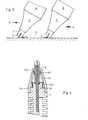
- FIG. 1 you can see the writing element, i. H. the front part of an ink pen 8 in longitudinal section.
- a feeder 1 contains surface chambers 1.2., An ink capillary 1.3. and an air groove 1.4.
- the ink capillary 1.3 cuts a central bore 1.5 in the feeder 1 in the region 1.6.
- a capillary rod 4 is inserted into this bore 1.5, which guides the ink from the ink capillary 1.3 to the writing tip. If the capillary rod is designed as a fiber wick, it can store more ink than an ordinary capillary groove in conventional ink pens. As a result, the ink flow cannot stop even at a fast writing speed.
- the feeder 1 is designed in the shape of a step in its front area, the front step 1.7 being frustoconical.
- a conical recess 1.1 is incorporated.
- a writing tube 2 with its conical end 2.2 is supported in this recess 1.1. Due to the fact that the cone angle of the recess 1.1 of the feeder 1 in the front end by 10 to 20 0 is greater than the cone angle of the end 2.2 of the write pipe 2, the write pipe 2 can be pivoted on all sides gimbal relative to the feeder 1, wherein the Kapillarstab 4 , which also penetrates the writing tube 2 to its front end, follows the movement elastically.
- a ball 3 made of hard metal is welded onto the front end of the writing tube 2. Both the ball 3 and the writing tube 2 are provided with capillary slots 3.1 and 2.1 in the front area. The slots 2.1 in the writing tube 2 are approximately twice the slot width deeper than the ball 3.
- a holder is used to hold the writing tube 2 on the feeder 1 Cuff 5 made of an elastic plastic, which is placed on stair-shaped heels on the feeder 1 and tapers towards the tip of the writing element.
- the attachment takes place, for example, by pressing the sleeve 5 onto an outer circumference 5.3 of the feeder 1.
- ring pockets 5.2 and 5.1 are incorporated, which form a capillary short circuit for the ink and prevent it from opening out to get the housing of the ink pen.
- the cuff 5 comprises the writing tube 2 at the front end 5.6 9 1eit, fixed at the rear end 5.4. It absorbs the radial component of the writing pressure and is dimensioned in terms of its bending stiffness in such a way that a spring elasticity similar to that which is customary with nibs arises.
- a finite spring travel is achieved without deformation of the writing element, while a fountain pen can be bent to permanent deformation, so that then no capillary transfer of ink from the feeder into the spring slot is possible.
- the tip of the writing tube 2 springs radially, the length dimension with which the sleeve 5 encompasses the writing tube 2 changes. Therefore, an area 5.5 is provided between the writing tube 2 and the inside of the sleeve 5, in which the sleeve 5 does not touch the tube 2. In the area of the ball 3, only the narrow ring web 5.6 of the sleeve 5 touches the tube 2 and can slide on it a few tenths of a millimeter.
- the ribbing 5.4 ensures close to the gimbal point 2.3, ie near the conical end 2.2 of the writing tube 2.
- the head of the feeder 1 is designed as a truncated cone 1.7 with an angle corresponding to the angle at the end 2.2 of the writing tube 2 so as not to cause the elastic deformation of the sleeve 5 to hinder.
- the ball 3 When looking at the tip of the writing element according to FIG. 2, the ball 3 can be seen with two capillary longitudinal slots 3.1 offset by 90 °. Instead of a double slit, triple and quadruple slits are also conceivable.
- FIG. 3 shows how the same ink meniscus 6 or 7 is formed between the ball and the paper surface 9 with the same position of the ink pen 8 despite different writing directions A or leg.
- the writing tip according to the invention then also delivers ink perfectly if the angle between the writing instrument and the paper surface is reduced to 10 0 .
- Writing is also successful when the writing instrument rotates axially.
- the maximum possible writing angle between the device axis and the paper surface is a maximum of 50 °, and with a conventional fountain pen it is not possible to rotate the writing device because the spring then scratches.
- An ink pen with the slide tip according to the invention can thus be used in the same way for right-handers, left-handers and oblique writers.
- FIG. 4 shows a further embodiment of the writing element.
- the front end 1.8 of the feeder 1 is cylindrical.
- a frustoconical spiral spring 10 with its large turns 10.2 comprises the front end 1.8 of the feeder 1, and with its small turns 10.1 the writing tube 2 in the front area.
- the spiral spring 10 thus ensures both the captive attachment of the Writing tube 2 on the feeder 1 and its gimbal elastic mobility.
- the spiral spring 10 is covered by a fixed sleeve 15, the front opening 15.1 of which is dimensioned such that sufficient space remains for the radial movement of the writing tube 2.
Landscapes
- Pens And Brushes (AREA)
Priority Applications (1)
| Application Number | Priority Date | Filing Date | Title |
|---|---|---|---|
| AT82112046T ATE14545T1 (de) | 1982-04-08 | 1982-12-28 | Tintenschreiber. |
Applications Claiming Priority (2)
| Application Number | Priority Date | Filing Date | Title |
|---|---|---|---|
| CH2208/82 | 1982-04-08 | ||
| CH220882 | 1982-04-08 |
Publications (2)
| Publication Number | Publication Date |
|---|---|
| EP0091516A1 true EP0091516A1 (fr) | 1983-10-19 |
| EP0091516B1 EP0091516B1 (fr) | 1985-07-31 |
Family
ID=4228413
Family Applications (1)
| Application Number | Title | Priority Date | Filing Date |
|---|---|---|---|
| EP82112046A Expired EP0091516B1 (fr) | 1982-04-08 | 1982-12-28 | Instrument d'écriture à encre |
Country Status (4)
| Country | Link |
|---|---|
| EP (1) | EP0091516B1 (fr) |
| JP (1) | JPS5911297A (fr) |
| AT (1) | ATE14545T1 (fr) |
| DE (1) | DE3265111D1 (fr) |
Cited By (3)
| Publication number | Priority date | Publication date | Assignee | Title |
|---|---|---|---|---|
| US6076987A (en) * | 1993-12-22 | 2000-06-20 | The Pilot Ink Co., Ltd. | Ballpoint pen and cap therefor |
| DE102009032230A1 (de) * | 2009-07-08 | 2011-01-13 | Vivapen D.O.O. | Tintenleitersystem für Schreibgeräte |
| EP3815921A1 (fr) * | 2019-10-29 | 2021-05-05 | Société BIC | Pointe pour stylo feutre d'écriture |
Citations (8)
| Publication number | Priority date | Publication date | Assignee | Title |
|---|---|---|---|---|
| GB191026585A (en) * | 1910-11-16 | 1911-08-31 | Alexander Munro | Improvements in Pen Nibs or Styles. |
| US2513380A (en) * | 1947-03-07 | 1950-07-04 | Esterbrook Pen Co | Writing instrument |
| DE822509C (de) * | 1950-07-06 | 1951-11-26 | Geha Werke Gmbh | Schreibroehrchen fuer Tintenfuellhalter |
| DE894973C (de) * | 1949-06-29 | 1953-10-29 | Georg Linz | Kugelschreiber |
| FR1142942A (fr) * | 1955-02-22 | 1957-09-24 | Stylographe à bille à liaison élastique | |
| FR1151093A (fr) * | 1956-05-25 | 1958-01-23 | Perfectionnements apportés aux stylographes à bille | |
| FR1209817A (fr) * | 1950-10-07 | 1960-03-03 | Perfectionnements apportés aux instruments pour écrire ou stylographes | |
| DE1561841A1 (de) * | 1967-11-18 | 1970-04-02 | Georg Linz | Schreibspitze fuer Faserschreiber mit in einem Roehrchen eingefassten Faserbuendeln |
-
1982
- 1982-12-28 DE DE8282112046T patent/DE3265111D1/de not_active Expired
- 1982-12-28 EP EP82112046A patent/EP0091516B1/fr not_active Expired
- 1982-12-28 AT AT82112046T patent/ATE14545T1/de not_active IP Right Cessation
-
1983
- 1983-04-06 JP JP58059410A patent/JPS5911297A/ja active Pending
Patent Citations (8)
| Publication number | Priority date | Publication date | Assignee | Title |
|---|---|---|---|---|
| GB191026585A (en) * | 1910-11-16 | 1911-08-31 | Alexander Munro | Improvements in Pen Nibs or Styles. |
| US2513380A (en) * | 1947-03-07 | 1950-07-04 | Esterbrook Pen Co | Writing instrument |
| DE894973C (de) * | 1949-06-29 | 1953-10-29 | Georg Linz | Kugelschreiber |
| DE822509C (de) * | 1950-07-06 | 1951-11-26 | Geha Werke Gmbh | Schreibroehrchen fuer Tintenfuellhalter |
| FR1209817A (fr) * | 1950-10-07 | 1960-03-03 | Perfectionnements apportés aux instruments pour écrire ou stylographes | |
| FR1142942A (fr) * | 1955-02-22 | 1957-09-24 | Stylographe à bille à liaison élastique | |
| FR1151093A (fr) * | 1956-05-25 | 1958-01-23 | Perfectionnements apportés aux stylographes à bille | |
| DE1561841A1 (de) * | 1967-11-18 | 1970-04-02 | Georg Linz | Schreibspitze fuer Faserschreiber mit in einem Roehrchen eingefassten Faserbuendeln |
Cited By (4)
| Publication number | Priority date | Publication date | Assignee | Title |
|---|---|---|---|---|
| US6076987A (en) * | 1993-12-22 | 2000-06-20 | The Pilot Ink Co., Ltd. | Ballpoint pen and cap therefor |
| DE102009032230A1 (de) * | 2009-07-08 | 2011-01-13 | Vivapen D.O.O. | Tintenleitersystem für Schreibgeräte |
| EP3815921A1 (fr) * | 2019-10-29 | 2021-05-05 | Société BIC | Pointe pour stylo feutre d'écriture |
| US11597231B2 (en) | 2019-10-29 | 2023-03-07 | SOCIéTé BIC | Nib for writing felt pen |
Also Published As
| Publication number | Publication date |
|---|---|
| EP0091516B1 (fr) | 1985-07-31 |
| DE3265111D1 (en) | 1985-09-05 |
| ATE14545T1 (de) | 1985-08-15 |
| JPS5911297A (ja) | 1984-01-20 |
Similar Documents
| Publication | Publication Date | Title |
|---|---|---|
| DE3141227C2 (de) | Schreibgerät | |
| DE2660589C2 (de) | Kugelhalterung eines Kugelschreibers | |
| DE3914465C2 (fr) | ||
| DE69308191T2 (de) | Schreibgerät | |
| DE3530906A1 (de) | Schreibstift | |
| DE3023189C2 (de) | Röhrchenschreibgerät | |
| DE3000214C3 (de) | Kugelschreiber | |
| DE2655264A1 (de) | Schreibelement fuer kugelspitzschreiber | |
| DE3321696C2 (fr) | ||
| EP0091516B1 (fr) | Instrument d'écriture à encre | |
| DE4137838C2 (de) | Schreibgerät | |
| DE1511403A1 (de) | Schreibgeraet mit Kapillarspalt | |
| DE3612792C2 (fr) | ||
| DE8513683U1 (de) | Schreibgerät | |
| DE1292037B (de) | Schreibfeder mit Schreibkugel | |
| DE2035353A1 (de) | Schreibgerät | |
| DE3802746A1 (de) | Zeichengeraet mit einer zeichenspitze, deren stirnflaeche die gezeichnete strichstaerke bestimmt | |
| DE3302528A1 (de) | Mine fuer kugelschreiber | |
| DE19502779C5 (de) | Druckbleistift | |
| DE10049488B4 (de) | Stift | |
| DE1956538C (de) | Füllschreibgerät | |
| DE4225313C2 (de) | Schreiborgan für einen Fineliner | |
| DE2063823A1 (de) | Füllstifte für dünne Bleiminen | |
| DE3426403C2 (de) | Röhrchenschreibspitze | |
| DE958992C (de) | Fuellschreibstift |
Legal Events
| Date | Code | Title | Description |
|---|---|---|---|
| PUAI | Public reference made under article 153(3) epc to a published international application that has entered the european phase |
Free format text: ORIGINAL CODE: 0009012 |
|
| 17P | Request for examination filed |
Effective date: 19821228 |
|
| AK | Designated contracting states |
Designated state(s): AT BE CH DE FR GB IT LI LU NL SE |
|
| ITF | It: translation for a ep patent filed | ||
| GRAA | (expected) grant |
Free format text: ORIGINAL CODE: 0009210 |
|
| AK | Designated contracting states |
Designated state(s): AT BE CH DE FR GB IT LI LU NL SE |
|
| REF | Corresponds to: |
Ref document number: 14545 Country of ref document: AT Date of ref document: 19850815 Kind code of ref document: T |
|
| REF | Corresponds to: |
Ref document number: 3265111 Country of ref document: DE Date of ref document: 19850905 |
|
| ET | Fr: translation filed | ||
| PLBE | No opposition filed within time limit |
Free format text: ORIGINAL CODE: 0009261 |
|
| STAA | Information on the status of an ep patent application or granted ep patent |
Free format text: STATUS: NO OPPOSITION FILED WITHIN TIME LIMIT |
|
| 26N | No opposition filed | ||
| ITTA | It: last paid annual fee | ||
| EPTA | Lu: last paid annual fee | ||
| REG | Reference to a national code |
Ref country code: CH Ref legal event code: PFA Free format text: PELIKAN GMBH |
|
| ITPR | It: changes in ownership of a european patent |
Owner name: TRASFORMAZIONE SOCIETARIA;PELIKAN GMBH |
|
| REG | Reference to a national code |
Ref country code: FR Ref legal event code: CJ |
|
| NLS | Nl: assignments of ep-patents |
Owner name: PELIKAN GMBH TE HANNOVER, BONDSREPUBLIEK DUITSLAND |
|
| EAL | Se: european patent in force in sweden |
Ref document number: 82112046.6 |
|
| PGFP | Annual fee paid to national office [announced via postgrant information from national office to epo] |
Ref country code: DE Payment date: 19961023 Year of fee payment: 15 |
|
| PGFP | Annual fee paid to national office [announced via postgrant information from national office to epo] |
Ref country code: CH Payment date: 19961121 Year of fee payment: 15 |
|
| PGFP | Annual fee paid to national office [announced via postgrant information from national office to epo] |
Ref country code: LU Payment date: 19961201 Year of fee payment: 15 |
|
| PGFP | Annual fee paid to national office [announced via postgrant information from national office to epo] |
Ref country code: SE Payment date: 19961202 Year of fee payment: 15 |
|
| PGFP | Annual fee paid to national office [announced via postgrant information from national office to epo] |
Ref country code: AT Payment date: 19961216 Year of fee payment: 15 |
|
| PGFP | Annual fee paid to national office [announced via postgrant information from national office to epo] |
Ref country code: FR Payment date: 19961219 Year of fee payment: 15 |
|
| PGFP | Annual fee paid to national office [announced via postgrant information from national office to epo] |
Ref country code: GB Payment date: 19961224 Year of fee payment: 15 |
|
| PGFP | Annual fee paid to national office [announced via postgrant information from national office to epo] |
Ref country code: NL Payment date: 19961231 Year of fee payment: 15 Ref country code: BE Payment date: 19961231 Year of fee payment: 15 |
|
| PG25 | Lapsed in a contracting state [announced via postgrant information from national office to epo] |
Ref country code: LU Free format text: LAPSE BECAUSE OF NON-PAYMENT OF DUE FEES Effective date: 19971228 Ref country code: GB Free format text: LAPSE BECAUSE OF NON-PAYMENT OF DUE FEES Effective date: 19971228 Ref country code: AT Free format text: LAPSE BECAUSE OF NON-PAYMENT OF DUE FEES Effective date: 19971228 |
|
| PG25 | Lapsed in a contracting state [announced via postgrant information from national office to epo] |
Ref country code: SE Free format text: LAPSE BECAUSE OF NON-PAYMENT OF DUE FEES Effective date: 19971229 |
|
| PG25 | Lapsed in a contracting state [announced via postgrant information from national office to epo] |
Ref country code: LI Free format text: LAPSE BECAUSE OF NON-PAYMENT OF DUE FEES Effective date: 19971231 Ref country code: FR Free format text: THE PATENT HAS BEEN ANNULLED BY A DECISION OF A NATIONAL AUTHORITY Effective date: 19971231 Ref country code: CH Free format text: LAPSE BECAUSE OF NON-PAYMENT OF DUE FEES Effective date: 19971231 Ref country code: BE Free format text: LAPSE BECAUSE OF NON-PAYMENT OF DUE FEES Effective date: 19971231 |
|
| BERE | Be: lapsed |
Owner name: PELIKAN G.M.B.H. Effective date: 19971231 |
|
| PG25 | Lapsed in a contracting state [announced via postgrant information from national office to epo] |
Ref country code: NL Free format text: LAPSE BECAUSE OF NON-PAYMENT OF DUE FEES Effective date: 19980701 |
|
| REG | Reference to a national code |
Ref country code: CH Ref legal event code: PL |
|
| GBPC | Gb: european patent ceased through non-payment of renewal fee |
Effective date: 19971228 |
|
| NLV4 | Nl: lapsed or anulled due to non-payment of the annual fee |
Effective date: 19980701 |
|
| PG25 | Lapsed in a contracting state [announced via postgrant information from national office to epo] |
Ref country code: DE Free format text: LAPSE BECAUSE OF NON-PAYMENT OF DUE FEES Effective date: 19980901 |
|
| EUG | Se: european patent has lapsed |
Ref document number: 82112046.6 |
|
| REG | Reference to a national code |
Ref country code: FR Ref legal event code: ST |