EP0091558A2 - Selbsttätige Führungsschiene für Motorsägen-Einheit - Google Patents
Selbsttätige Führungsschiene für Motorsägen-Einheit Download PDFInfo
- Publication number
- EP0091558A2 EP0091558A2 EP83102258A EP83102258A EP0091558A2 EP 0091558 A2 EP0091558 A2 EP 0091558A2 EP 83102258 A EP83102258 A EP 83102258A EP 83102258 A EP83102258 A EP 83102258A EP 0091558 A2 EP0091558 A2 EP 0091558A2
- Authority
- EP
- European Patent Office
- Prior art keywords
- support arm
- fence
- saw
- members
- structure according
- Prior art date
- Legal status (The legal status is an assumption and is not a legal conclusion. Google has not performed a legal analysis and makes no representation as to the accuracy of the status listed.)
- Withdrawn
Links
Images

Classifications
-
- B—PERFORMING OPERATIONS; TRANSPORTING
- B23—MACHINE TOOLS; METAL-WORKING NOT OTHERWISE PROVIDED FOR
- B23D—PLANING; SLOTTING; SHEARING; BROACHING; SAWING; FILING; SCRAPING; LIKE OPERATIONS FOR WORKING METAL BY REMOVING MATERIAL, NOT OTHERWISE PROVIDED FOR
- B23D59/00—Accessories specially designed for sawing machines or sawing devices
- B23D59/001—Measuring or control devices, e.g. for automatic control of work feed pressure on band saw blade
- B23D59/005—Measuring or control devices, e.g. for automatic control of work feed pressure on band saw blade for preventing collision of saw blades with other machine parts or workpieces
-
- B—PERFORMING OPERATIONS; TRANSPORTING
- B23—MACHINE TOOLS; METAL-WORKING NOT OTHERWISE PROVIDED FOR
- B23D—PLANING; SLOTTING; SHEARING; BROACHING; SAWING; FILING; SCRAPING; LIKE OPERATIONS FOR WORKING METAL BY REMOVING MATERIAL, NOT OTHERWISE PROVIDED FOR
- B23D45/00—Sawing machines or sawing devices with circular saw blades or with friction saw discs
- B23D45/02—Sawing machines or sawing devices with circular saw blades or with friction saw discs with a circular saw blade or the stock mounted on a carriage
- B23D45/021—Sawing machines or sawing devices with circular saw blades or with friction saw discs with a circular saw blade or the stock mounted on a carriage with the saw blade mounted on a carriage
- B23D45/024—Sawing machines or sawing devices with circular saw blades or with friction saw discs with a circular saw blade or the stock mounted on a carriage with the saw blade mounted on a carriage the saw blade being adjustable according to depth or angle of cut
-
- B—PERFORMING OPERATIONS; TRANSPORTING
- B27—WORKING OR PRESERVING WOOD OR SIMILAR MATERIAL; NAILING OR STAPLING MACHINES IN GENERAL
- B27B—SAWS FOR WOOD OR SIMILAR MATERIAL; COMPONENTS OR ACCESSORIES THEREFOR
- B27B27/00—Guide fences or stops for timber in saw mills or sawing machines; Measuring equipment thereon
- B27B27/10—Devices for moving or adjusting the guide fences or stops
-
- B—PERFORMING OPERATIONS; TRANSPORTING
- B27—WORKING OR PRESERVING WOOD OR SIMILAR MATERIAL; NAILING OR STAPLING MACHINES IN GENERAL
- B27B—SAWS FOR WOOD OR SIMILAR MATERIAL; COMPONENTS OR ACCESSORIES THEREFOR
- B27B5/00—Sawing machines working with circular or cylindrical saw blades; Components or equipment therefor
- B27B5/10—Wheeled circular saws; Circular saws designed to be attached to tractors or other vehicles and driven by same
-
- Y—GENERAL TAGGING OF NEW TECHNOLOGICAL DEVELOPMENTS; GENERAL TAGGING OF CROSS-SECTIONAL TECHNOLOGIES SPANNING OVER SEVERAL SECTIONS OF THE IPC; TECHNICAL SUBJECTS COVERED BY FORMER USPC CROSS-REFERENCE ART COLLECTIONS [XRACs] AND DIGESTS
- Y10—TECHNICAL SUBJECTS COVERED BY FORMER USPC
- Y10T—TECHNICAL SUBJECTS COVERED BY FORMER US CLASSIFICATION
- Y10T83/00—Cutting
- Y10T83/748—With work immobilizer
- Y10T83/7593—Work-stop abutment
- Y10T83/76—With scale or indicator
-
- Y—GENERAL TAGGING OF NEW TECHNOLOGICAL DEVELOPMENTS; GENERAL TAGGING OF CROSS-SECTIONAL TECHNOLOGIES SPANNING OVER SEVERAL SECTIONS OF THE IPC; TECHNICAL SUBJECTS COVERED BY FORMER USPC CROSS-REFERENCE ART COLLECTIONS [XRACs] AND DIGESTS
- Y10—TECHNICAL SUBJECTS COVERED BY FORMER USPC
- Y10T—TECHNICAL SUBJECTS COVERED BY FORMER US CLASSIFICATION
- Y10T83/00—Cutting
- Y10T83/748—With work immobilizer
- Y10T83/7593—Work-stop abutment
- Y10T83/7607—Normal to plane of cut
- Y10T83/7613—Adjustable
- Y10T83/762—Angularly relative to plane of cut; e.g., miter
-
- Y—GENERAL TAGGING OF NEW TECHNOLOGICAL DEVELOPMENTS; GENERAL TAGGING OF CROSS-SECTIONAL TECHNOLOGIES SPANNING OVER SEVERAL SECTIONS OF THE IPC; TECHNICAL SUBJECTS COVERED BY FORMER USPC CROSS-REFERENCE ART COLLECTIONS [XRACs] AND DIGESTS
- Y10—TECHNICAL SUBJECTS COVERED BY FORMER USPC
- Y10T—TECHNICAL SUBJECTS COVERED BY FORMER US CLASSIFICATION
- Y10T83/00—Cutting
- Y10T83/768—Rotatable disc tool pair or tool and carrier
- Y10T83/7684—With means to support work relative to tool[s]
- Y10T83/7693—Tool moved relative to work-support during cutting
- Y10T83/7697—Tool angularly adjustable relative to work-support
-
- Y—GENERAL TAGGING OF NEW TECHNOLOGICAL DEVELOPMENTS; GENERAL TAGGING OF CROSS-SECTIONAL TECHNOLOGIES SPANNING OVER SEVERAL SECTIONS OF THE IPC; TECHNICAL SUBJECTS COVERED BY FORMER USPC CROSS-REFERENCE ART COLLECTIONS [XRACs] AND DIGESTS
- Y10—TECHNICAL SUBJECTS COVERED BY FORMER USPC
- Y10T—TECHNICAL SUBJECTS COVERED BY FORMER US CLASSIFICATION
- Y10T83/00—Cutting
- Y10T83/869—Means to drive or to guide tool
- Y10T83/8773—Bevel or miter cut
Definitions
- the invention pertains to a motorized saw unit of the bias-cutting type which can be selectively set for cross-cutting and mitering elongated workpiece. Additionally the unit includes fence members that automatically align themselves in operative association with the saw when the latter is being positioned to form a predetermined angular cut.
- U.S. Patent 4,211,134 is a saw unit of the radial arm type and is provided with a single fence member of the self-aligning type.
- the motorized saw unit includes a supporting frame having a horizontal support arm mounted for selective rotatable movement thereon.
- the ends of this support arm are each provided with an upwardly directed trunnion member that includes integral boss elements adapted to fixedly support the ends of a pair of spaced parallel guide rods.
- These guide rods define track elements for slidably supporting the motorized saw.
- a worktable is fixed on and for rotative movement with the support arm and is provided with a cutting channel which the saw is caused to follow during the performance of its intended function.
- a link rod is operatively connected intermediate its ends with the support arm and is caused to move longitudinally during selective rotation of the support arm.
- a pair of aligned fence members have their adjacent ends disposed in operative association with the cutting channel and their opposite ends are operatively connected to the link rod which effects simultaneous movement of the fence members whereby their adjacent ends are maintained in operative association or close proximity with the cutting channel during selective rotative movement of the support arm.
- Another object is to provide such a saw that is readily collapsible and movable from one location to another.
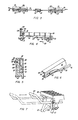
- the motorized saw unit is identified generally by numeral 10.
- the saw includes a supporting frame consisting of tubular members 12 and 14 and bar members 16 (Figs. 1 and 4).
- the tubular members 14 are horizontally disposed and those identified by numeral 12 depend from the underside of the unit defining legs and with the assistance of the bar members 16 the latter tubular members can be folded so that the unit can be transported from one location to another by means of a pair of wheel members 18 (one only shown in Fig. 1) rotatably mounted on the supporting frame.
- the saw unit includes a horizontally disposed support arm 20 that is mounted for selective rotatable movement intermediate its ends as at 22.
- the forward end of the support arm 20 is identified in Figs. 1 and 2 by numeral 24 and that portion of said support arm immediately adjacent to said forward end is disposed in close proximity with a miter indexing plate 26 having an arcuated band of mitering indicia 28.
- the upper surface of the support arm 20 has a circular worktable 30 fixed thereon which is provided with a cutting channel 32 that is in alignment with the longitudinal axis of the support arm 20.
- Each end of the support arm 20 has a trunnion member mounted for pivotal movement thereon with the forward trunnion member being identified by numeral 34 and the rear one by numeral 36.
- These trunnion members are in alignment one with the other and both are provided with integral boss members 38 and 40 respectively which serve to anchor the ends of a pair of spaced and parallel guide rods 42 and 44.
- the guide rods 42 and 44 define track elements for slidably supporting a motorized saw identified generally in Fig. 1 by numeral 46.
- the saw 46 includes a drive motor 48, a handle 50 for effecting manual movement of the saw along the guide rods 42 and 44. Additionally the saw is provided with a cutting blade 52 and a well known form of blade guard 54.
- the rear trunnion member 36 is operatively associated with an arcuate band of indicating indicia or bevel scale 56 and the forward trunnion member 34 (Fig. 1) being connected to the rear one by guide rods 42 and 44 provides a means whereby they move in unison when selectively pivoted.
- the forward trunnion member 34 has a bevel clamp lever 58 operatively associated therewith and serves to lock the trunnion members 34 and 36 in any angular setting selected on the bevel scale 56.
- the cutting blade 52 is always disposed in operative association with the cutting channel 32 regardless of the mitering position of said worktable or angular setting of said trunnion members.
- the miter indexing plate 26 is provided with automatic positioning stops 60 for the support arm 20 at the more common saw mitering positions and is locked in these positions when selected by a spring biased pin 62 having a control knob 64 fixed on the outer end thereof.
- Worktable extensions 66 and 68 are mounted on the supporting frame on each side of and in close proximity with the worktable 30.
- Each of these worktable extensions 66 and.68 has a fence support member attached to the rear side thereof which are identified in Fig. 2 by numerals 70 and 72 respectively.
- these fence support members 70 and 72 have a stepped configuration (Figs. 4 and 5) and provide a means for the assembly of a channel guide 74 intermediate the rear side of the worktable extensions and the upwardly directed inner sutface of the fence support members 70 and 72.
- These channel guides 74 are adapted to slidably support the end portions of a link rod 76 as shown in Figs. 2 and 3.
- the link rod 76 intermediate its ends is provided with a depending roller 78 (Fig.
- FIG. 3 which is adapted to ride within a channel 80 (Fig. 2) formed in the support arm 20.
- This channel 80 extends along a portion of the longitudinal axis of the support arm 20 as shown in Fig. 2 and any selective rotative movement of said support arm causes longitudinal movement of the link rod 76 within the channel guides 74.
- a pair of spaced and aligned fence members 82 and 84 are n ounted for simultaneous sliding movement on the worktable 30 and its associated worktable extensions 66 and 68.
- These fence members 82 and 84 are moved longitudinally and simultaneously by means of fence link levers 86 and 88 respectively which interconnect said fence members with opposite ends-of the link rod 76.
- one end of fence link lever 86 assembles on a pin 90 attached to the link rod 76 and the opposite end of said fence link lever is fixed to the underside of the fence member 82 by means of a bolt 92.
- fence link lever 88 interconnects the opposite end of the link rod 76 with the fence member 84 in the same manner as fence link lever 86 is connected to fence member 82.
- each fence member 82 and 84 connected to the link rod 7.6 as described supra, it is obvious that said fence members are longitudinally and simultaneously moved with each selective rotative movement of the support arm 20.
- the fence members are extruded as shown in Figs. 5 and 6 and are guided during their longitudinal movement in close proximity with their respective fence support member by means of a depending lip 94 disposed in engagement with the upper rear surface of said fence support member.
- each fence member includes a pair of vertically spaced and aligned rib members 96 and 98 (Figs. 5 and 6) which serve to hold the fence member in close proximity with their respective fence supports by means of a round head bolt 100 as shown in Fig. 5.
- Bolt member 100 also serves as a means for placing each fence member (82, 84) in locking engagement with its respective fence support member.
- Thi's locking feature is accomplished by means of a locking lever 104 assembled on the threaded portion of the bolt 100 by means of a nut 106 (Fig. 5). This locking lever extends in a downwardly direction and at a point intermediate its ends it engages a bulbous rib 108 formed on rear side of the fence support members.
- the locking lever 104 adjacent its lower end is operatively connected to a linkage rod 110 which in turn is connected to a linkage rod 112 (Fig. 4) having offset portions (not shown) that define cranks on which the eye portion 114 of an actuating linkage rod 116 is assembled.
- the end of rod 116 opposite the eye portion 114 is provided with a control knob 118.
- the worktable extension has a tubular extendable wing member 122 operatively associated therewith which serves as means for accommodating elongated workpieces of excessive length.
- This extendable wing member includes a spring biased locking bar 124 for maintaining it in any desired location.
- the extendable wing member 122 serves as a means for manually manipulating the saw unit on its wheel members 18 to effect transporting the same from one location to another.
Landscapes
- Life Sciences & Earth Sciences (AREA)
- Engineering & Computer Science (AREA)
- Mechanical Engineering (AREA)
- Wood Science & Technology (AREA)
- Forests & Forestry (AREA)
- Sawing (AREA)
Applications Claiming Priority (2)
| Application Number | Priority Date | Filing Date | Title |
|---|---|---|---|
| US367814 | 1982-04-12 | ||
| US06/367,814 US4452117A (en) | 1982-04-12 | 1982-04-12 | Self-adjusting fence for motorized saw unit |
Publications (2)
| Publication Number | Publication Date |
|---|---|
| EP0091558A2 true EP0091558A2 (de) | 1983-10-19 |
| EP0091558A3 EP0091558A3 (de) | 1985-10-02 |
Family
ID=23448728
Family Applications (1)
| Application Number | Title | Priority Date | Filing Date |
|---|---|---|---|
| EP83102258A Withdrawn EP0091558A3 (de) | 1982-04-12 | 1983-03-08 | Selbsttätige Führungsschiene für Motorsägen-Einheit |
Country Status (6)
| Country | Link |
|---|---|
| US (1) | US4452117A (de) |
| EP (1) | EP0091558A3 (de) |
| JP (1) | JPS58186520A (de) |
| CA (1) | CA1193945A (de) |
| DE (1) | DE91558T1 (de) |
| ZA (1) | ZA831624B (de) |
Cited By (11)
| Publication number | Priority date | Publication date | Assignee | Title |
|---|---|---|---|---|
| GB2164292A (en) * | 1983-03-21 | 1986-03-19 | Olof Birger Larsson | Saw accessory |
| GB2270032A (en) * | 1992-08-28 | 1994-03-02 | Black & Decker Inc | A sawbench with a fence |
| EP0638399A1 (de) * | 1993-08-12 | 1995-02-15 | Black & Decker Inc. | Anlageteilführungsvorrichtung für Motorsägen |
| EP0752300A1 (de) * | 1995-07-07 | 1997-01-08 | Black & Decker Inc. | Einstellbarer Anschlag für eine Kapp- und Gehrungssäge |
| USD381667S (en) | 1995-12-08 | 1997-07-29 | Milwaukee Electric Tool Corporation | Compound miter saw |
| US6474206B1 (en) | 1995-12-12 | 2002-11-05 | Black & Decker Inc. | Miter saw with wear plates and orientation system therefor |
| US6810780B2 (en) | 2001-05-10 | 2004-11-02 | Black & Decker Inc. | Miter detent override for a sliding compound miter saw |
| EP2156930A3 (de) * | 2008-08-22 | 2011-07-27 | Black & Decker Inc. | Verfahren und Vorrichtung zur automatischen Einstellung des Führungslineals einer Gehrungssäge |
| CN102985204A (zh) * | 2010-05-27 | 2013-03-20 | 革新电动工具有限公司 | 斜切锯 |
| TWI480120B (zh) * | 2011-11-23 | 2015-04-11 | 力山工業股份有限公司 | 工件擋板調整裝置 |
| IT202100033137A1 (it) * | 2021-12-30 | 2023-06-30 | Studio A Automazione | Macchina per l’automazione di taglio del pane carasau |
Families Citing this family (98)
| Publication number | Priority date | Publication date | Assignee | Title |
|---|---|---|---|---|
| JPS6078224U (ja) * | 1983-11-05 | 1985-05-31 | 株式会社日立工機原町 | 切断機のバイス調整装置 |
| US4576076A (en) * | 1984-10-16 | 1986-03-18 | Speed Cut, Inc. | Multiple intersecting planes cutting device |
| JPS61284401A (ja) * | 1985-06-12 | 1986-12-15 | 株式会社マキタ | 丸鋸盤における切断残片の遮断装置 |
| JPH0518082Y2 (de) * | 1987-02-20 | 1993-05-14 | ||
| USD306031S (en) | 1988-01-11 | 1990-02-13 | Hitachi Koki Haramachi Co., Ltd. | Mitre saw |
| US4875399A (en) * | 1988-06-23 | 1989-10-24 | Scott William D | Miter box attachment for cutting crown mouldings and the like |
| US4934233B1 (en) * | 1988-06-29 | 1994-08-23 | Emerson Electric Co | Compound miter saw |
| US4890657A (en) * | 1988-12-16 | 1990-01-02 | The Shelhorse Corporation | Apparatus and method for employing a portable workshop |
| US5063805A (en) * | 1989-11-08 | 1991-11-12 | Emerson Electric Co. | Compound miter saw |
| JPH0721281Y2 (ja) * | 1990-01-13 | 1995-05-17 | リョービ株式会社 | 切断角度可変丸鋸装置 |
| DE4106636C1 (de) * | 1991-02-28 | 1992-06-04 | Black & Decker Inc., Newark, Del., Us | |
| US5297463A (en) * | 1991-10-09 | 1994-03-29 | Black & Decker Inc. | Adjustable fence for compound miter saw |
| US6899005B1 (en) * | 1991-10-09 | 2005-05-31 | Black & Decker Inc. | Adjustable fence for compound miter saw |
| US5181448A (en) * | 1991-12-20 | 1993-01-26 | Emerson Electric Co. | Miter saw apparatus with adjustable workpiece supporting fence |
| US5868054A (en) * | 1992-02-24 | 1999-02-09 | Tapco International Corporation | Portable saw table |
| US6070696A (en) * | 1992-02-24 | 2000-06-06 | Tapco International Corporation | Adjustable leg support assembly |
| US5651298A (en) * | 1992-02-24 | 1997-07-29 | Tapco Products Company, Inc. | Portable saw table |
| CA2082760A1 (en) * | 1992-02-24 | 1993-08-25 | Douglas G. Break | Portable saw table |
| US6212983B1 (en) * | 1992-03-04 | 2001-04-10 | Stoddard H. Pyle | Tiltable infeed and outfeed saw table |
| USD345743S (en) | 1992-03-25 | 1994-04-05 | Delta International Machinery Corp. | Motorized miter box |
| US5235889A (en) * | 1992-03-25 | 1993-08-17 | Delta International Machinery Corp. | Compound miter saw |
| DE69313011T2 (de) * | 1992-05-22 | 1998-03-19 | Makita Corp | Gehrungssäge |
| US5193598A (en) * | 1992-06-23 | 1993-03-16 | Estrem Jim J | Portable support stand attachable to a sawhorse |
| JP2613156B2 (ja) * | 1992-08-27 | 1997-05-21 | 株式会社マキタ | 卓上丸鋸盤 |
| USD352509S (en) | 1993-05-06 | 1994-11-15 | Porter-Cable Corporation | Miter saw |
| US5404779A (en) * | 1993-06-09 | 1995-04-11 | Tapco Products Company, Inc. | Saw table with compound movement of saw |
| US5473968A (en) * | 1993-08-25 | 1995-12-12 | Tapco Products Company, Inc. | Tilting saw table |
| CA2150066A1 (en) * | 1994-07-08 | 1996-01-09 | Andrew L. Itzov | Adjustable workpiece support apparatus for a compound miter saw |
| USD376806S (en) | 1994-07-20 | 1996-12-24 | Milwaukee Electric Tool Corporation | Compound miter saw |
| US5623860A (en) * | 1994-12-15 | 1997-04-29 | Emerson Electric Co. | Adjustable/bypassable bevel stop for compound miter saw |
| GB2304075B (en) * | 1995-08-10 | 1999-10-20 | Milwaukee Electric Tool Corp | Indexing override mechanism for a slide compound miter saw |
| US5819624A (en) * | 1996-07-30 | 1998-10-13 | Milwaukee Electric Tool Corporation | Indexing override mechanism for a slide compound miter saw |
| EP1285723A3 (de) * | 1995-09-22 | 2003-03-19 | Black & Decker Inc. | Bohrständer mit teleskopierbarem Verlängerungsarm |
| US6631661B2 (en) * | 1995-12-12 | 2003-10-14 | Black & Decker Inc. | Bevel locking system for a sliding compound miter saw |
| US5802943A (en) * | 1996-12-05 | 1998-09-08 | Black & Decker Inc. | Bevel locking system for a sliding compound miter saw |
| US5870938A (en) * | 1995-12-12 | 1999-02-16 | Black & Decker Inc. | Bevel locking system for a sliding compound miter saw |
| US5907987A (en) * | 1996-12-05 | 1999-06-01 | Stumpf; William R. | Bevel locking system for a sliding compound miter saw |
| US6032562A (en) * | 1995-12-12 | 2000-03-07 | Black & Decker Inc. | Bevel locking system for a sliding compound miter saw |
| US5875828A (en) * | 1997-07-24 | 1999-03-02 | Black & Decker, Inc. | Portable work bench |
| CN1191907C (zh) * | 1998-03-11 | 2005-03-09 | 布莱克和戴克公司 | 锯器 |
| US6152009A (en) * | 1998-08-13 | 2000-11-28 | Jorgensen; Daniel D. | Architectural millwork jig |
| US6705192B2 (en) * | 2001-02-09 | 2004-03-16 | Tapco International Corporation | Folding saw table |
| US6478664B2 (en) | 2001-03-12 | 2002-11-12 | One World Technologies, Inc. | Cut-off saw |
| US7021186B2 (en) * | 2001-08-10 | 2006-04-04 | Eastway Fair Company Limited | Bevel adjustment mechanism for a compound miter saw |
| US7104174B1 (en) * | 2001-08-31 | 2006-09-12 | Lumberchief | Log sawing apparatus and method |
| US7127977B2 (en) * | 2002-02-11 | 2006-10-31 | Porter-Cable/Delta | Remotely actuated beveling systems for a miter saw |
| US7114425B2 (en) * | 2002-04-30 | 2006-10-03 | Credo Technology Corporation | Fine-adjustment mechanism to preset a miter saw for precision miter cuts |
| US10941828B2 (en) | 2002-06-25 | 2021-03-09 | Fox Factory, Inc. | Gas spring with travel control |
| US7311028B2 (en) * | 2002-06-25 | 2007-12-25 | Black & Decker Inc. | Front bevel indicator/front bevel lock |
| US20080296814A1 (en) | 2002-06-25 | 2008-12-04 | Joseph Franklin | Gas spring with travel control |
| US8464850B2 (en) | 2006-11-16 | 2013-06-18 | Fox Factory, Inc. | Gas spring curve control in an adjustable-volume gas-pressurized device |
| US7703585B2 (en) | 2002-06-25 | 2010-04-27 | Fox Factory, Inc. | Integrated and self-contained suspension assembly having an on-the-fly adjustable air spring |
| US7963509B2 (en) | 2007-01-31 | 2011-06-21 | Fox Factory, Inc. | Travel control for a gas spring and gas spring having very short travel modes |
| US20050076759A1 (en) * | 2003-10-08 | 2005-04-14 | Brian Westfall | Linear saw with stab-cut bevel capability |
| US20040069106A1 (en) * | 2002-10-14 | 2004-04-15 | Mcadoo David L. | Linear feed cutting apparatus and method |
| US7201090B2 (en) * | 2002-10-16 | 2007-04-10 | Robert Bosch Gmbh | Front-accessible bevel locking system |
| USD481401S1 (en) | 2002-11-05 | 2003-10-28 | Emerson Electric Co. | Compound miter saw |
| US20040089125A1 (en) * | 2002-11-08 | 2004-05-13 | Emerson Electric Co. | Compound miter saw |
| US20040250901A1 (en) * | 2002-12-02 | 2004-12-16 | Mike Ursell | Collapsible stand |
| US6868612B2 (en) * | 2003-07-18 | 2005-03-22 | Willard E. Ballard | Cutting guide device for circular saws |
| JP4534549B2 (ja) * | 2004-03-26 | 2010-09-01 | 日立工機株式会社 | 卓上切断機 |
| US20050247178A1 (en) * | 2004-04-15 | 2005-11-10 | Hetcher Jason D | Power tool having an elastomeric material |
| US20060236833A1 (en) * | 2005-04-25 | 2006-10-26 | Meredith Daryl S | Fence arrangement for a miter saw |
| US20060266189A1 (en) * | 2005-05-27 | 2006-11-30 | Yuehting Chen | Saw blade angular adjustment device for a metal and wood cutting machine |
| US20080276773A1 (en) * | 2006-03-30 | 2008-11-13 | Radhakrishna Shesha Iyengar Togare | Multipurpose cutting method for cutting various materials |
| CN200945562Y (zh) * | 2006-08-23 | 2007-09-12 | 南京德朔实业有限公司 | 锯 |
| US7631847B2 (en) * | 2007-02-27 | 2009-12-15 | Techtronic Power Tools Technology Limited | Power tool bracket |
| GB0723700D0 (en) * | 2007-12-04 | 2008-01-16 | Gmca Pty Ltd | Power tool cutting apparatus |
| WO2009130938A1 (ja) * | 2008-04-21 | 2009-10-29 | 株式会社 マキタ | 卓上丸鋸盤用治具及び卓上丸鋸盤 |
| US20090293691A1 (en) * | 2008-05-30 | 2009-12-03 | Gehret Robert S | Detent Switch for a Power Tool |
| US20090301277A1 (en) * | 2008-06-09 | 2009-12-10 | Aleksander Ipatenco | Saw With Moveable Material Support Surface |
| US7849773B1 (en) * | 2008-06-25 | 2010-12-14 | Aubrey Eugene Hamby | Radial arm framework with integral roof pitch (angle) saw guide |
| CA2731602C (en) * | 2008-07-22 | 2013-09-10 | Gerhard Weusthof | Docking and miter saw |
| DE202008016713U1 (de) * | 2008-12-18 | 2010-04-29 | Metabowerke Gmbh | Werkzeugmaschine, insbesondere Kapp- und Gehrungssäge |
| DE202008016711U1 (de) * | 2008-12-18 | 2010-05-12 | Metabowerke Gmbh | Werkzeugmaschine, insbesondere Kapp- und Gehrungssäge |
| US8250956B2 (en) * | 2009-04-28 | 2012-08-28 | Robert Bosch Gmbh | Miter saw with work surface extensions |
| US8661956B2 (en) * | 2009-08-13 | 2014-03-04 | Robert Bosch Gmbh | Rear mounted miter saw fence |
| US20110036227A1 (en) * | 2009-08-14 | 2011-02-17 | Stuart William C | Multi saw compound miter jig and method therefor |
| TWI391212B (zh) * | 2010-06-02 | 2013-04-01 | Rexon Ind Corp Ltd | 可調整寬度的工作台 |
| DE102011005019A1 (de) * | 2011-03-03 | 2012-09-06 | Robert Bosch Gmbh | Werkzeugmaschinensystem |
| US9649703B2 (en) * | 2012-03-15 | 2017-05-16 | Rexon Industrial Corp., Ltd. | Circular saw with a moving mechanism |
| JP5656915B2 (ja) * | 2012-05-21 | 2015-01-21 | ユニ・チャーム株式会社 | トウを含む複数の繊維を有するウエブ部材の切断装置、及び切断方法 |
| JP5871711B2 (ja) * | 2012-05-21 | 2016-03-01 | ユニ・チャーム株式会社 | トウを含む複数の繊維を有するウエブ部材の切断装置、及び切断方法 |
| JP5836194B2 (ja) * | 2012-05-21 | 2015-12-24 | ユニ・チャーム株式会社 | トウを含む複数の繊維を有する連続ウエブの切断装置、及び切断方法 |
| US20160144522A1 (en) * | 2012-12-07 | 2016-05-26 | Charlie Zhang | Cutting tool |
| US20140318341A1 (en) * | 2013-04-25 | 2014-10-30 | Anton Fait | Saw with articuable side vice and stop |
| EP3083171B1 (de) * | 2013-12-16 | 2020-06-03 | Robert Bosch GmbH | Gehrungswinkelarretierungsmechanismus für elektrowerkzeug und elektrowerkzeug |
| US10442106B2 (en) * | 2014-03-31 | 2019-10-15 | Sawstop Holding Llc | Extension rails for table saws |
| US9649776B2 (en) * | 2014-09-09 | 2017-05-16 | Michael W. Appling | Portable saw apparatus for cutting oversized substrates |
| TWI535512B (zh) * | 2014-09-12 | 2016-06-01 | 力山工業股份有限公司 | 可折疊的鋸切機及鋸切機的折疊方法 |
| USD796561S1 (en) * | 2015-08-25 | 2017-09-05 | Chester Bronson Andrews, III | Mitre saw fence scale |
| US11045887B2 (en) | 2015-11-02 | 2021-06-29 | Tti (Macao Commercial Offshore) Limited | Miter saw |
| CN105397181B (zh) * | 2015-12-10 | 2017-12-15 | 济南华信自动化工程有限公司 | 一种全自动高效下料锯床 |
| US10022887B2 (en) | 2016-08-26 | 2018-07-17 | Johannes Hogenhout | Miter saw extendable fence attachment |
| US11027346B2 (en) * | 2018-01-20 | 2021-06-08 | Clean Cutters LLC | Dustless one-stroke cut-through saw |
| US10610939B1 (en) * | 2018-01-20 | 2020-04-07 | Clean Cutters LLC | Dustless one-stroke cut-through saw |
| US12186817B2 (en) * | 2020-12-02 | 2025-01-07 | Makita Corporation | Sliding cutting machine |
| CA3178006A1 (en) | 2022-01-07 | 2023-07-07 | Carbotech International | Plank positioning mechanism |
Family Cites Families (9)
| Publication number | Priority date | Publication date | Assignee | Title |
|---|---|---|---|---|
| GB503487A (en) * | 1937-10-04 | 1939-04-04 | W E Chivers & Sons Ltd | Improvements in or relating to apparatus for the cutting or marking of roof timbers or other material |
| US2249814A (en) * | 1940-01-15 | 1941-07-22 | Wallace Abrasive Machinery Com | Cut-off machine |
| US3302669A (en) * | 1964-06-29 | 1967-02-07 | Edler Adolph | Motor powered radial arm tool support |
| US3384135A (en) * | 1966-07-01 | 1968-05-21 | Arthur J. Frydenlund | Guide means for saws |
| US4002094A (en) * | 1975-08-11 | 1977-01-11 | Quick Rip Corporation | Metal saw |
| US4152961A (en) * | 1978-01-18 | 1979-05-08 | The Singer Company | Radial saw |
| DE2809201A1 (de) * | 1978-03-03 | 1979-09-06 | Bosch Gmbh Robert | Kreissaegetisch, insbesondere fuer heimwerker |
| US4355557A (en) * | 1978-10-02 | 1982-10-26 | Mecsey Michael A | Apparatus for sawing a wood piece in conformance with a template configuration |
| US4211134A (en) * | 1979-03-26 | 1980-07-08 | Excor, Inc. | Self-aligning fence for radial arm saw |
-
1982
- 1982-04-12 US US06/367,814 patent/US4452117A/en not_active Expired - Fee Related
-
1983
- 1983-03-01 CA CA000422596A patent/CA1193945A/en not_active Expired
- 1983-03-08 DE DE198383102258T patent/DE91558T1/de active Pending
- 1983-03-08 EP EP83102258A patent/EP0091558A3/de not_active Withdrawn
- 1983-03-09 ZA ZA831624A patent/ZA831624B/xx unknown
- 1983-04-11 JP JP58063523A patent/JPS58186520A/ja active Pending
Cited By (21)
| Publication number | Priority date | Publication date | Assignee | Title |
|---|---|---|---|---|
| GB2164292A (en) * | 1983-03-21 | 1986-03-19 | Olof Birger Larsson | Saw accessory |
| GB2270032A (en) * | 1992-08-28 | 1994-03-02 | Black & Decker Inc | A sawbench with a fence |
| US5737986A (en) * | 1993-08-12 | 1998-04-14 | Black & Decker Inc. | Power saw fence guide |
| EP0638399A1 (de) * | 1993-08-12 | 1995-02-15 | Black & Decker Inc. | Anlageteilführungsvorrichtung für Motorsägen |
| US6021700A (en) * | 1993-08-12 | 2000-02-08 | Black & Decker Inc. | Power saw fence guide |
| US5651297A (en) * | 1993-08-12 | 1997-07-29 | Black & Decker Inc. | Power saw fence guide |
| EP0752300A1 (de) * | 1995-07-07 | 1997-01-08 | Black & Decker Inc. | Einstellbarer Anschlag für eine Kapp- und Gehrungssäge |
| US5755148A (en) * | 1995-07-07 | 1998-05-26 | Black & Decker Inc. | Adjustable fence for a compound miter saw |
| US5943931A (en) * | 1995-07-07 | 1999-08-31 | Black & Decker Inc. | Adjustable fence for a compound miter saw |
| US5957022A (en) * | 1995-07-07 | 1999-09-28 | Black & Decker Inc. | Adjustable fence for a compound miter saw |
| US6425309B1 (en) | 1995-07-07 | 2002-07-30 | Black & Decker Inc. | Adjustable fence for a compound miter saw |
| EP0997243A1 (de) * | 1995-07-07 | 2000-05-03 | Black & Decker Inc. | Einstellbarer Anschlag für eine Kapp- und Gehrungssäge |
| US6418830B1 (en) | 1995-07-07 | 2002-07-16 | Black & Decker Inc. | Adjustable fence for a compound miter saw |
| USD381667S (en) | 1995-12-08 | 1997-07-29 | Milwaukee Electric Tool Corporation | Compound miter saw |
| US6474206B1 (en) | 1995-12-12 | 2002-11-05 | Black & Decker Inc. | Miter saw with wear plates and orientation system therefor |
| US6810780B2 (en) | 2001-05-10 | 2004-11-02 | Black & Decker Inc. | Miter detent override for a sliding compound miter saw |
| EP2156930A3 (de) * | 2008-08-22 | 2011-07-27 | Black & Decker Inc. | Verfahren und Vorrichtung zur automatischen Einstellung des Führungslineals einer Gehrungssäge |
| US9833924B2 (en) | 2008-08-22 | 2017-12-05 | Black & Decker Inc. | Method and apparatus for automatically adjusting a miter saw fence |
| CN102985204A (zh) * | 2010-05-27 | 2013-03-20 | 革新电动工具有限公司 | 斜切锯 |
| TWI480120B (zh) * | 2011-11-23 | 2015-04-11 | 力山工業股份有限公司 | 工件擋板調整裝置 |
| IT202100033137A1 (it) * | 2021-12-30 | 2023-06-30 | Studio A Automazione | Macchina per l’automazione di taglio del pane carasau |
Also Published As
| Publication number | Publication date |
|---|---|
| US4452117A (en) | 1984-06-05 |
| ZA831624B (en) | 1983-11-30 |
| CA1193945A (en) | 1985-09-24 |
| DE91558T1 (de) | 1984-02-16 |
| JPS58186520A (ja) | 1983-10-31 |
| EP0091558A3 (de) | 1985-10-02 |
Similar Documents
| Publication | Publication Date | Title |
|---|---|---|
| US4452117A (en) | Self-adjusting fence for motorized saw unit | |
| CA1082079A (en) | Radial saw | |
| US4537105A (en) | Circular cross-cut and miter saw box | |
| CA2036664C (en) | Portable circular saw | |
| AU2007200238B2 (en) | Saw | |
| US5181446A (en) | Self-aligning quick pick-off rip fence | |
| EP0014869B1 (de) | Kreissäge | |
| DE2813825A1 (de) | Motorbetriebene tischkreissaege | |
| CA1205359A (en) | Safety device for rocking arm saw | |
| US4553462A (en) | Radial arm saw | |
| US5842400A (en) | Table saw assembly | |
| US4122604A (en) | Lumber forming attachment for chain saws | |
| US3380494A (en) | Wood component member cutting apparatus | |
| GB2045158A (en) | Self-aligning fence for radial arm saw | |
| CA1041403A (en) | Saw for cutting truss members, rafters and the like with dimensional accuracy | |
| US3565137A (en) | Ball track carriage construction | |
| US4280472A (en) | Masonry saw | |
| US1756287A (en) | Wood-sawing machine | |
| CH393716A (de) | Kreissäge mit einem dem Sägeblatt nachgeschalteten Spaltkeil | |
| US6675486B2 (en) | Portable bandsaw | |
| EP0481186B1 (de) | Gehrungskappsäge | |
| US3128801A (en) | Brede | |
| DE4033785A1 (de) | Gehrungssaege | |
| EP2249990A1 (de) | Kappsäge mit einer staubabsaugung und/oder einer verkleidung | |
| DE3537298C2 (de) |
Legal Events
| Date | Code | Title | Description |
|---|---|---|---|
| PUAI | Public reference made under article 153(3) epc to a published international application that has entered the european phase |
Free format text: ORIGINAL CODE: 0009012 |
|
| AK | Designated contracting states |
Designated state(s): CH DE IT LI |
|
| ITCL | It: translation for ep claims filed |
Representative=s name: STUDIO BUGNIO S.P.A. |
|
| DET | De: translation of patent claims | ||
| RAP1 | Party data changed (applicant data changed or rights of an application transferred) |
Owner name: DELTA INTERNATIONAL MACHINERY CORP. |
|
| PUAL | Search report despatched |
Free format text: ORIGINAL CODE: 0009013 |
|
| AK | Designated contracting states |
Designated state(s): CH DE IT LI |
|
| STAA | Information on the status of an ep patent application or granted ep patent |
Free format text: STATUS: THE APPLICATION IS DEEMED TO BE WITHDRAWN |
|
| 18D | Application deemed to be withdrawn |
Effective date: 19860603 |
|
| RIN1 | Information on inventor provided before grant (corrected) |
Inventor name: RICKMERS, CLIFFORD P. Inventor name: DONOVAN, BOBBY B. Inventor name: BRICKNER, LOUIS C. Inventor name: GUNTHARP, CHARLES D. |